Table of Contents
Advertisement
Quick Links
Download this manual
See also:
User Manual
Advertisement
Table of Contents

Related Manuals for CNB IVC5055VR


Summary of Contents for CNB IVC5055VR
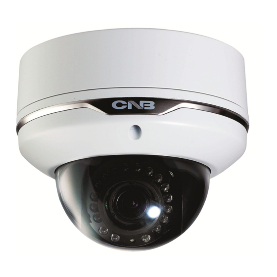
- Page 1 Ver. 1.0 XNET Network Vandal Resistant Dome Camera (IVC5055VR) Installation Manual...
-
Page 2: About This Manual
Important Notices The copyright of this manual is owned by CNB Technology Inc. It is illegal to copy and distribute this manual without permission. Damages caused by use of parts not recommended and by misuse will not be applicable for support. -
Page 3: Table Of Contents
Index 1. About XNET ........................4 1.1. About XNET ..........................4 1.2. Features of XNET ........................4 1.3. Applications ..........................4 2. About the Product ......................5 2.1. Contents ........................... 5 2.2. Product Information ........................5 2.3. Hardware Designation ......................6 2.3.1. -
Page 4: About Xnet
1. About XNET XNET is an internet based security and surveillance system that is compatible with various network conditions through easy installation and user interface as well as multi-functional compressor Codec such as H.264, MJPEG. XNET provides stable real-time surveillance by real time video/ audio at 1080P level, local storage for any network problems, and hybrid IP technology that can be used with existing analog CCTV devices. -
Page 5: About The Product
Connect the Power Adaptor DC jack SCREW 3EA, Wall Anchors 3EA Accessory L (wrench) 1EA Install CD XNET Viewer Program (IVC5055VR) IP-Installer (CNB-CMS) IP Dome Camera A software that assigns an IP address A software that monitors and records (IVC5055VR) -
Page 6: Hardware Designation
This shows Camera module inside the dome cover. Analog video output Analog Video Output Factory Reset button Power Terminal Recalls factory default configurations Act,Link LED EVENT LED : EVENT Alarm Out signal is turned on. SYSTEM LED : The camera at the end of boot PWR LED : that power is connected Indicates SD CARD... -
Page 7: Connecting Cables
LINE COLOR FUNCTION BROWN Alarm-Out(+) ORANGE Alarm-Out(-) BLUE Alarm-In(+) GREEN Alarm-In(-) MIC/Line-in WHITE Line-Out BLACK GRAY Not Used YELLOW Not Used Power Input Use the cable adapter(DC12V JACK) in the package to connect power. Please use the accessory power supply provided in the package. Except when connected to AC24V DC jack please use(DC12V/2A,AC24V 2.5A) Analog Video Output Use this output for immediate monitoring of the video during installation. - Page 8 Alarm Connection These wires connect to Alarm input/output devices. Alarm Sensor Input: Connect to Alarm sensor devices such as IR Sensor or Heat sensor. These can be configured to normally close or normally open operation. (#1, #2) Alarm Output: Connect to Alarm devices such as Relay operated Siren Lamp or Alarm Light.
-
Page 9: Connecting To Alarm Devices
Alarm Input Wires from various sensor type (IR, heat, and magnetic) can be connected to Alarm in(+)/(-) terminal as shown in figure 2.5. (NC or NO of sensor input can be selected at Menu screen.) Alarm Sensor device requires a separate power source. Internal Circuitry External Circuitry Alarm Output... -
Page 10: Software Installation
Mount the Camera to a ceiling or a wall. Make sure the base is firm enough to hold the Camera. Guide Pattern Case Bottom Mounting Screw Dome Base Inner Dome Dome Cover IVC5055VR Model Adjust the position, zoom, and focus as shown below: TILT : 90˚ FOCUS ZOOM Horizontal Rotation : 360˚... -
Page 11: Cable Connection
Connect XNET to PC directly User can monitor and configure XNET camera by connecting it to your PC directly. 1. Connect XNET camera to your PC directly using a LAN cable like below. COMPUTER Crossover Network Cable NOTE: XNET camera’s IP address will be automatically set to the default value, 192.168.123.100, after connecting XNET camera to your PC directly. - Page 12 3. Please insert the Setup CD into your CD-ROM drive, and then please setup IPInstaller program. 4. Please click ‘Next’ button when the Setup screen appear. 5. Please click ‘Install’ button to begin the Installation. 6. Please click ‘Finish’ button to complete the installation. 12 / 21...
- Page 13 7. XNET IP Installer program is automatically launched like below right after the program installation. Please double click XNET camera on the list. 8. XNET camera is successfully connected to your PC. (Internet Explorer will prompt you to install ActiveX. In order to view video, you must accept the ActiveX download.
- Page 14 Connect XNET with a router Please connect XNET camera and PC to a router using LAN cables like below. NETWORK HUB COMPUTER Direct Network Cable NOTE: If DHCP server is enabled at your router, XNET camera automatically receives an IP address from your router. Otherwise, XNET camera’s IP address will be automatically set to the default value, 192.168.123.100.
-
Page 15: Installing Ip-Installer Software And Configuring Ip Address
A unique IP address has to be configured in order to connect IP camera and monitoring PC to a network. IP- Installer software provided in the Installation CD (included in the package and also available to download from our website http://www.cnbtec.com) will configure IP address easily. If your network have a DHCP server that automatically assigns IP addresses to IP cameras. - Page 16 2. Select the camera of which you wish to change the IP address and click (Set IP Address) button to bring up the following box in Figure 3-3. Figure 3-3. IP Address box 3. When you enter the IP address and click Set button, the box shown in Figure 3-4 will appear. Figure 3-4.
-
Page 17: Using Web Viewer
4. Using Web Viewer Connecting to network devices can be done using internet web browser or “XNET-CMS” software. This manual explains about using internet web browser only. For instructions on how to configure network connection using XNET-CMS software, please refer to XNET-CMS Manual, which can be found in the installation CD. -
Page 18: Web Viewer Page
Web viewer page consists of Video monitor screen and menu option buttons. Figure 4-2. Web Viewer Page 18 / 21... - Page 19 Item Sub Item Description Captures and saves the current image as a still picture. Capture The image is saved as jpeg file in the following folder: C:₩xNetCapture Brings up Menu screen. Setup page for each XNET feature can be opened from this Menu screen. Setting Please refer to [XNET Owner’s Manual] for detail.
-
Page 20: Specification
5. Specification IVC5055VR Specifications Signal System Progressive image processing Scanning System 16:9 Progressive Pixel Clock 80MHz Image Sensor 1/3" Progressive CMOS Sensor Sync. System Internal Effective Pixels Number 1920 (H) x 1080(V) 2.0 Mega Horizontal Resolution 1100 TV Lines Video Output Level Select NTSC/PAL 1.0Vp-p (BNC 75Ω, composite) - Page 21 21 / 21...
Need help?
Do you have a question about the IVC5055VR and is the answer not in the manual?
Questions and answers