
Related Manuals for CNB IDC4050IR


Summary of Contents for CNB IDC4050IR
- Page 1 Ver. 1.1 XNET Network Dome Camera (IDC4050IR/IDC4050F/IDC4050VR/IDC4050VF) Installation Manual...
-
Page 2: About This Manual
About this Manual A compatibility and durability test ensured this product’s high performance. This manual is for XNET IP Dome Camera users only, and it describes operations related to XNET IP Dome Camera. Please read this manual thoroughly paying attention to cautions and warnings before using the product even if you have used similar products before. -
Page 3: Table Of Contents
Index 1. About XNET ........................4 1.1. About XNET ........................4 1.2. Features of XNET ......................4 1.3. Applications ........................4 2. About the Product ......................5 2.1. Contents ......................... 5 2.2. Product Information ......................5 2.2.1 Product Composition....................5 2.3. -
Page 4: About Xnet
1. About XNET XNET is an internet based security and surveillance system that is compatible with various network conditions through easy installation and user interface as well as multi-functional compressor Codec such as H.264, MJPEG. XNET provides stable real-time surveillance by real time video/ audio at 1080P level, local storage for any network problems, and hybrid IP technology that can be used with existing analog CCTV devices. -
Page 5: About The Product
OUTPUT : 12VDC 2A GUIDE PATTERN Guide Pattern Software and User’s manual Accessory Terminal (8P) 1EA, SCREW 3EA, Wall Anchors 3EA Install CD XNET (IDC4050IR, IDC4050F, Viewer Program IP-Installer IDC4050VR, IDC4050VF) (XNET-CMS) IP Dome Camera A software that assigns an IP... -
Page 6: Hardware Designation
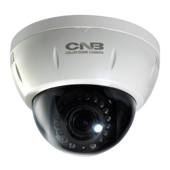
This shows Camera module inside the dome cover. Analog Video Output Network Terminal Power Terminal Factory Reset button Recalls factory default configurations Alarm Input/Output Network DC FAN PWR,CPU,EVENT LED Mic/Audio Input CDS Sensor Megafixel IR LED fixed lens Factory Reset Press and hold for more than 3 seconds while power is on to recall factory default settings Adjusting Lens Focus Adjust: Adjust the Focus using a knob. -
Page 7: Connecting Cables
Analog Video Output Use this output to monitor the analog video signal while installing. (Select Video Out at menu screen to enable this output) Power Supplies Power to the Xnet product. Use 12V DC Adapter in the package. Connect to a Monitor Connect to an Adaptor... - Page 8 Audio Connection MIC/Line Input (Mono) Connects to auxiliary Audio Device or microphone. Line Output (Mono) Audio signal output to a Power Amplified device or Speaker. This can be used to listen to the audio signal sent from a remote PC for Bi-directional Audio communication. ALARM Input/Output Connect to Alarm Input and Output Sensor Input : Wires from various sensor type (IR, heat, and magnetic) can be connected.
-
Page 9: Connecting To Alarm Devices
Alarm Input Wires from various sensor type (IR, heat, and magnetic) can be connected to Alarm in(+)/(-) terminal as shown in figure 2.5. (NC or NO of sensor input can be selected at Menu screen.) Alarm Sensor device requires a separate power source. Internal Circuitry External Circuitry Alarm Output... -
Page 10: Software Installation
If you have questions about details not explained in this section or if the product is not functioning as described, please refer to FAQ before contacting the store. Mount the Camera to a ceiling or a wall. Make sure the base is firm enough to hold the Camera. IDC4050IR Model 10 / 17... -
Page 11: Cable Connection
Adjust the position, zoom, and focus as shown below: TILT : 90˚ FOCUS Horizontal ZOOM Rotation : 360˚ PAN : 360˚ 1. A PC or a laptop computer is required to set up an IP address. Compatible operating system: Windows 2000/ Windows XP/ Windows Vista Since the default IP address of the device is 192.168.123.100, set up the IP address of the computer like the following: IP Address : 192.168.123.101 Subnet Mask : 255.255.255.0... -
Page 12: Installing Ip-Installer Software And Configuring Ip Address
A unique IP address has to be configured in order to connect IP camera and monitoring PC to a network. IP- Installer software provided in the Installation CD (included in the package) will configure IP address easily. If your network have a DHCP server that automatically assigns IP addresses to IP cameras. If your network does not have a DHCP server, the default IP address of the device is 192.168.123.100. - Page 13 2. Select the camera of which you wish to change the IP address and click (Set IP Address) button to bring up the following box in Figure 3-3. Figure 3-3. IP Address box 3. When you enter the IP address and click Set button, the box shown in Figure 3-4 will appear. Figure 3-4.
-
Page 14: Using Web Viewer
4. Using Web Viewer Connecting to network devices can be done using internet web browser or “XNET-CMS” software. This guide explains about using internet web browser only. For instructions on how to configure network connection using XNET-CMS software, please refer to XNET-CMS Manual, which can be found in the installation CD. -
Page 15: Web Viewer Page
Web viewer page consists of Video monitor screen and menu option buttons. Figure 4-2 Web Viewer Page Item Sub Item Description Captures and saves the current image as a still picture. Capture The image is saved as jpeg file in the following folder: C:₩xNetCapture Brings up Menu screen. -
Page 16: Specification
0.8Lux (Color, DSS On), 0.00 Lux (IR LED On) *IDC4050VR 850nm / 45˚ IR LED 18EA, Sensor 1EA IR LED and Sensor *IDC4050IR / IDC4050VR (IR model Only) IR LED Lighting Distance Max. 15m Day & Night System ICR(CDS Type) - Page 17 17 / 17...
Need help?
Do you have a question about the IDC4050IR and is the answer not in the manual?
Questions and answers