Table of Contents
Advertisement
Quick Links
Download this manual
See also:
Installation Manaul
Advertisement
Table of Contents

Related Manuals for CNB IDP4030VR


Summary of Contents for CNB IDP4030VR
- Page 1 XNET Network Dome Camera Install Guide ( IDP4030VR , IVP4030VR ) Ver. 1.0 (090905) 1 / 17...
-
Page 2: About This Manual
Important Notices The copyright of this manual is owned by CNB Technology Inc. It is illegal to copy and distribute this manual without permission. Damages caused by use of parts not recommended and by misuse will not be applicable for support. -
Page 3: Table Of Contents
Index 1. About XNET ............................4 1.1. About XNET ..........................4 1.2. Features of XNET ........................4 1.3. Applications ..........................4 2. About the Product .........................5 2.1. Contents ..........................5 2.2. Product Information .......................5 2.3. Hardware Designation ......................6 2.3.1. Switch and Controls ....................6 2.3.2 Connecting Cables .......................7 2.3.3 Connecting to Alarm Devices ..................8... -
Page 4: About Xnet
1. About XNET XNET is an internet based security and surveillance system that is compatible with various network conditions through easy installation and user interface as well as multi-functional compressor Codec such as MJPEG, MPEG-4, and H.264. XNET provides stable real-time surveillance by real time video/ audio at SXGA level, local storage for any network problems, and hybrid IP technology that can be used with existing analog CCTV devices. -
Page 5: About The Product
2. About the Product Please make sure the following contents are included when you open the package Contents Description Additional info. XNET XNET Network Dome Camera AC Power Cable 2Jack Cable Terminal Terminal for Alarm and Audio Software and User’s manual Install CD XNET Viewer Program... -
Page 6: Hardware Designation
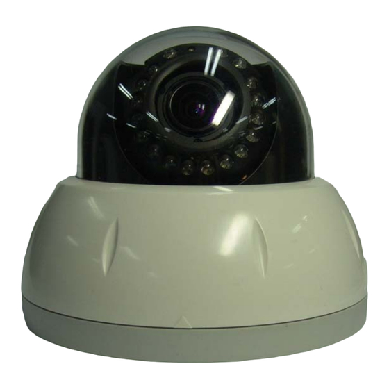
This shows Camera module inside the dome cover. Alarm Input/Output Mic/Audio Input Audio Output Analog Video Output Network Power Terminal Zoom Adjust Factory Reset button Recalls factory default Focus Adjust configurations CDS Sensor IR LED This CDS Sensor detects Low Light (night) and turns on IR LEDs. -
Page 7: Connecting Cables
Power Supplies Power to the Xnet product. Use 12V DC Adapter in the package. Do not use this connector when powering up the product through LAN cable. (PoE) The product is not covered under warranty when it is damaged by connecting both Ethernet power and 12V DC power to this terminal. -
Page 8: Connecting To Alarm Devices
Network Terminal This Ethernet terminal connects to 100Mbps LAN through an RJ-45 connector. When optional PoE is used, the power will be supplied from the Network Cable. Link LED Yellow light indicates that the network is properly connected. Act LED Green light indicates that the XNET system connected to 100Mbps LAN. -
Page 9: Software Installation
3.Software Installation This section provides brief guidelines to install the XNET quickly and to monitor XNET’s Video and Audio signals easily. If you have questions about details not explained in this section or if the product is not functioning as described, please refer to FAQ before contacting the store. http://www.cnbtec.com Our homepage is Mount the Camera to a ceiling or a wall. -
Page 10: Cable Connection
Adjust the position, zoom, and focus as shown below: TILT : 90˚ FOCUS Horizontal ZOOM Rotation : 360˚ PAN : 360˚ 1.A PC or a laptop computer is required to set up an IP address. Compatible operating system: Windows 2000/ Windows XP/ Windows Vista Since the default IP address of the device is 192.168.123.100, set up the IP address of the computer like the following: IP Address : 192.168.123.101 Subnet Mask : 255.255.255.0... -
Page 11: Installing Ip-Installer Software And Configuring Ip Address
A unique IP address has to be configured in order to connect network camera and monitoring PC to a network. IP-Installer software provided in the Installation CD (included in the package and also available to download from our website http://www.cnbtec.com) will configure IP address easily. If your network have a DHCP server that automatically assigns IP addresses to network cameras. - Page 12 B. Select the camera of which you wish to change the IP address and click (Set IP Address) button to bring up the following box in Figure 3-3. Figure 3-3. IP Address box C. When you enter the IP address and click Set button, the box shown in Figure 3-4 will appear. Figure 3-4.
-
Page 13: Using Web Viewer
4.Using Web Viewer Connecting to network devices can be done using internet web browser or “XNET-CMS” software. This guide explains about using internet web browser only. For instructions on how to configure network connection using XNET-CMS software, please refer to XNET-CMS Manual, which can be found in the installation CD. -
Page 14: Web Viewer Page
Web viewer page consists of Video monitor screen and menu option buttons. Figure 4-2 Web Viewer Page... -
Page 15: Specification
Live View Dual-Codec needs to be enabled in Video Setup Page in order for Sub Sub Stream Stream to be displayed. Please refer to [XNET Owner’s Manual] for detail. 5.Specification IDP4030VR/IVP4030VR Specifications Camera Signal System Progressive Image processing Scanning System... - Page 16 Network IPv4, TCP, UDP, RTSP, RTCP, RTP, HTTP, SMTP, FTP, DHCP, UPnP, Protocol Bonjour, DNS, DynDNS, IGMP, SAP, ICMP, ARP Supported DDNS CNB DDNS, DyncDDNS.org, Reference code with SDK Video access from Camera live view for up to 10 clients...
Need help?
Do you have a question about the IDP4030VR and is the answer not in the manual?
Questions and answers