Table of Contents
Advertisement
Quick Links
Advertisement
Table of Contents

Related Manuals for CNB IGP1030


Summary of Contents for CNB IGP1030
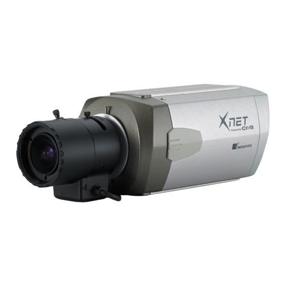
- Page 1 Ver. 1.0 XNET Network Box Camera (IGP1030) Installation Manual...
- Page 2 Important Notices The copyright of this manual is owned by CNB Technology Inc. It is illegal to copy and distribute this manual without permission. Damages caused by use of not suggested parts and misuse will not be applicable for support.
-
Page 3: Table Of Contents
XNET Network Box Camera Installation Manual Index 1 . About XNET ........................4 1.1. About XNET ..........................4 1.2. Features of XNET ........................4 1.3. Applications ..........................4 2 . About the Product ......................5 2.1. Contents ..........................5 2.2. Product Information ........................ 5 2.3. -
Page 4: About Xnet
XNET Network Box Camera Installation Manual 1. About XNET XNET is an internet based security and surveillance system that is compatible with various network conditions through easy installation and user interface as well as multi-functional compressor Codec such as MJPEG, MPEG-4, and H.264. -
Page 5: About The Product
AC power Cord 2 jack cable Software and User’s manual Install CD XNET Viewer Program (IGP1030) IP-Installer (XNET-NVR) A software that monitors and records Network Camera (Lens not A software that assigns an IP Audio and Video signal from the... -
Page 6: Functions And Designations
XNET Network Box Camera Installation Manual Mounting Screw Hole Auto Iris control plug 1/4”. 20 UNC(20 THREAD) L : 4.5mm +-0.2mm (ISO standard) or 0.197” (ASA standard) CS Ring Fix Screw Lens(Sold Separately) CS Ring Please ask at the store about purchasing lens separately. Attach CS Ring only to use CS-mount Lens Figure 2-1. -
Page 7: Rear View
XNET Network Box Camera Installation Manual RS-485 and alarm Input/ Output Analog video Output Power Input Factory Reset Button for 12 VDC Recalls initial factory settings POWER LED Network Terminal Event LED Mic / audio Input Audio Output SD CARD Slot Figure 2-2. -
Page 8: Connecting To Alarm Devices
XNET Network Box Camera Installation Manual NETWORK : This Ethernet terminal connects to 10Mbps or 100Mbps LAN through an RJ-45 connector. When optional PoE is used, the power will be supplied from the Network Cable. LINK : Yellow light indicates that he network is properly connected. ACT : Green light indicates that the XNET system connected to 100Mbps LAN. - Page 9 XNET Network Box Camera Installation Manual Alarm Input Wires from various sensor type (IR, heat, and magnetic) can be connected to Alarm in(+)/(-) terminal as shown in figure 2.5. (NC or NO of sensor input can be selected at Menu screen.) Alarm Sensor device requires a separate power source.
-
Page 10: Software Installation
XNET Network Box Camera Installation Manual 3. Software Installation This section provides brief guidelines to install the XNET software quickly and to monitor XNET’s Video and Audio signals easily. If you have questions about details not explained in this section or if the product is not functioning as described, please refer to FAQ before contacting the store. -
Page 11: Installing Ip-Installer Software And Configuring Ip Address
XNET Network Box Camera Installation Manual A unique IP address has to be configured in order to connect network camera and monitoring PC to a network. IP-Installer software provided in the Installation CD (included in the package and also available to download from our website http://www.cnbtec.com) will configure IP address easily. - Page 12 XNET Network Box Camera Installation Manual 2. Select the camera of which you wish to change the IP address and click (Set IP Address) button to bring up the following box in Figure 3-3. Figure 3-3. IP Address box 3. When you enter the IP address and click Set button, the box shown in Figure 3-4 will appear. Figure 3-4.
-
Page 13: Using Web Viewer
XNET Network Box Camera Installation Manual 4. Using Web Viewer Connecting to network devices can be done using internet web browser or “XNET-CMS” software. This guide explains about using internet web browser only. For instructions on how to configure network connection using XNET-CMS software, please refer to XNET-CMS Manual, which can be found in the installation CD. - Page 14 XNET Network Box Camera Installation Manual Enter the user name and password to bring up the web viewer page. The default id and password is “root”, “admin” respectively. If you want to use a different HTTP port number from the default value, simply put a colon and port number at the end of the IP address.
-
Page 15: Web Viewer Page
XNET Network Box Camera Installation Manual Web viewer page consists of Video monitor screen and menu option buttons. Figure 4-2. Web Viewer Page 15 / 18... - Page 16 XNET Network Box Camera Installation Manual Item Sub Item Description Captures and saves the current image as a still picture. Capture The image is saved as jpeg file in the following folder: C:₩xNetCapture Brings up Menu screen. Setup page for each XNET feature can be opened from this Menu screen. Setting Please refer to [XNET Owner’s Manual] for detail.
-
Page 17: Specifications
Two-way (full duplex / ADPCM G.726) Ipv4, HTTP, HTTPs, UDP, TCP, RTSP, RTP, SMTP, FTP, ICMP, DHCP, UPnP, Bonjour, Protocol ARP, DNS, DynDNS, NTP, IGMP(Multicast) *) OnVif 1. CNB DDNS 2. DynDNS.org Supported DDNS 3. Reference code with SDK Network... - Page 18 Live view for up to 10 user clients Monitoring Application Video Snapshot to file (JPEG) XNET NVR, CNB CMS and Utility (IP-Installer, etc) System Control CNB Camera Management tool on CD and web-based configuration System Upgrade Firmware upgrade over HTTP Maintenance PTZ control (RS-485)
Need help?
Do you have a question about the IGP1030 and is the answer not in the manual?
Questions and answers