
Related Manuals for Intel S2600IP


Summary of Contents for Intel S2600IP
- Page 1 ® Intel Server Board S2600IP and ® Intel Workstation Board W2600CR Technical Product Specification Intel order number G34153-003 Revision 1.1 June, 2012 Enterprise Platforms and Services Division - Marketing...
- Page 2 No license, express or implied, by estoppel or otherwise, to any intellectual property rights is granted by this document. Except as provided in Intel's Terms and Conditions of Sale for such products, Intel assumes no liability whatsoever, and Intel disclaims any...
-
Page 3: Table Of Contents
Intel® Server Board S2600IP and Intel® Workstation Board W2600CR TPS Table of Contents Table of Contents 1. Introduction ........................1 Chapter Outline ...................... 1 Server Board Use Disclaimer ................. 1 2. Product Overview ....................... 2 Product Feature Set ....................3 2.1.1... - Page 4 Table of Contents Intel® Server Board S2600IP and Intel® Workstation Board W2600CR TPS 3.3.22 KVM/Serial Over Lan (SOL) Function ..............38 3.3.23 On-board SAS/SATA Support and Options ............38 PCI Subsystem ....................39 Network Interface Controller ................. 40 3.5.1 Network Interface ....................40 ®...
- Page 5 Intel® Server Board S2600IP and Intel® Workstation Board W2600CR TPS Table of Contents 4.5.2 User Model ......................65 4.5.3 LAN Interface ....................... 66 BMC Firmware Update ..................76 4.6.1 The BMC firmware release Number ..............76 4.6.2 Boot Recovery Mode .................... 76 4.6.3...
- Page 6 Table of Contents Intel® Server Board S2600IP and Intel® Workstation Board W2600CR TPS 6.4.3 TPM Connector ....................96 6.4.4 PMBus* Connector ....................96 6.4.5 Chassis Intrusion Header ..................96 6.4.6 IPMB Connector ....................96 FAN Connectors ....................96 6.5.1 System FAN Connectors ..................97 6.5.2...
- Page 7 Intel® Server Board S2600IP and Intel® Workstation Board W2600CR TPS Table of Contents 9.4.8 Closed loop stability ................... 117 9.4.9 Residual Voltage Immunity in Standby mode ............. 117 9.4.10 Common Mode Noise ..................117 9.4.11 Soft Starting ....................... 118 9.4.12 Zero Load Stability Requirements ..............
- Page 8 Table of Contents Intel® Server Board S2600IP and Intel® Workstation Board W2600CR TPS Power unit support ......................155 ® Redundant Fans only for Intel Server Chassis ..............155 Fan Fault LED support...................... 155 Memory Throttling support ....................155 Appendix D: POST Code Diagnostic LED Decoder ............156 Appendix E: POST Error Messages and Handling..............
- Page 9 Intel® Server Board S2600IP and Intel® Workstation Board W2600CR TPS List of Figures List of Figures ® Figure 1. Intel Server Board S2600IP ..................2 ® Figure 2. Intel Workstation Board W2600CR ................2 ® Figure 3. Intel Server Board S2600IP Major Components ............6 ®...
- Page 10 List of Tables Intel® Server Board S2600IP and Intel® Workstation Board W2600CR TPS List of Tables Table 1. Product Feature Set ...................... 3 Table 2. Mixed Processor Configurations Error Summary............23 Table 3. UDIMM Support Guidelines ..................27 Table 4. RDIMM Support Guidelines ..................28 Table 5.
- Page 11 Intel® Server Board S2600IP and Intel® Workstation Board W2600CR TPS List of Tables Table 37. Multiport SAS/SATA Connector Pin-out ("SCU_0 (0-3)") ........... 93 Table 38. Multiport SAS/SATA Connector Pin-out ("SCU_1 (4-7)") ........... 93 ® Table 39. Intel RAID C600 Upgrade Key Connector Pin-out ............ 94 Table 40.
- Page 12 List of Tables Intel® Server Board S2600IP and Intel® Workstation Board W2600CR TPS ® Table 78. Intel Workstation Board W2600CR - Chassis-specific sensors ......154 ® Table 79. Intel Workstation Board W2600CR - Fan domain definition ........154 ® Table 80. Intel Server Chassis P4304 (UPL) Power support ..........
- Page 13 Intel® Server Board S2600IP and Intel® Workstation Board W2600CR TPS List of Tables <This page is intentionally left blank.> Revision 1.1 xiii Intel order number G34153-003...
-
Page 15: Introduction
It is the responsibility of the system integrator who chooses not to use Intel developed server building blocks to consult vendor datasheets and operating parameters to determine the amount of airflow required for their specific application and environmental conditions. -
Page 16: Product Overview
Product Overview Intel® Server Board S2600IP and Intel® Workstation Board W2600CR TPS Product Overview ® ® The Intel Server Board S2600IP and Intel Workstation Board W2600CR are Enterprise I/O Rich platforms for Pedestal and Rack Server and workstation market. ®... -
Page 17: Product Feature Set
Intel® Server Board S2600IP and Intel® Workstation Board W2600CR TPS Product Overview Product Feature Set Table 1. Product Feature Set ® ® Board Name Intel Server Board S2600IP Intel Workstation Board W2600CR ® ® ® ® Support for one or two Intel... - Page 18 Product Overview Intel® Server Board S2600IP and Intel® Workstation Board W2600CR TPS ® ® Board Name Intel Server Board S2600IP Intel Workstation Board W2600CR Audio None ALC889 HD Audio (7.1 + S/PDIF Out) 4 Rear USB2.0 1 Rear Serial A 4 Rear USB2.0...
-
Page 19: Main Board Connector And Component Layout
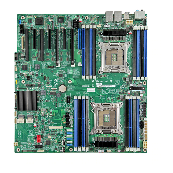
Intel® Server Board S2600IP and Intel® Workstation Board W2600CR TPS Product Overview 2.1.1 Main Board Connector and Component Layout The following figure shows the layout of the server board. Each connector and major component is identified by a number or letter, and a description is given below the figure. -
Page 20: Figure 3. Intel ® Server Board S2600Ip Major Components
Product Overview Intel® Server Board S2600IP and Intel® Workstation Board W2600CR TPS Callout Description Callout Description Slot 8, PCI Express* Gen2 SATA Port 1 DIMM E1/E2/F1/F2 SATA Port 0 Status LED CPLD Update ID LED IPMB Diagnostic LED HDD LED... - Page 21 Intel® Server Board S2600IP and Intel® Workstation Board W2600CR TPS Product Overview Callout Description Callout Description Slot 1, PCI Express* Gen3 DIMM C1/C2/D1/D2 RMM4 Lite module System Fan connector 1/2/3/4/5/6 Slot 2, PCI Express* Gen3 Type A USB connector Type A USB connector...
-
Page 22: Main Board Rear I/O Layout
Product Overview Intel® Server Board S2600IP and Intel® Workstation Board W2600CR TPS Callout Description Callout Description SPDIF connector HDD LED USB 2/3, NIC 2 ME FRC UPDT USB 0/1, NIC 1 CMOS CLR USB3.0 0/1(W2600CR only) BIOS RCVRY HD Audio (W2600CR only) -
Page 23: Figure 5. Intel ® Workstation Board W2600Cr Rear I/O Layout
Intel® Server Board S2600IP and Intel® Workstation Board W2600CR TPS Product Overview Callout Description Callout Description Diagnostics LED’s 7.1 Channel HD Audio Jack Connector USB3.0 Port 0(bottom) and 1(top) ID LED NIC Port 1, USB Port 0 (bottom) and 1... -
Page 24: Server Board Mechanical Drawings
Product Overview Intel® Server Board S2600IP and Intel® Workstation Board W2600CR TPS 2.1.3 Server Board Mechanical Drawings Figure 6. Mounting Hole Locations (1 of 2) Revision 1.1 Intel order number G34153-003... -
Page 25: Figure 7. Mounting Hole Locations (2 Of 2)
Intel® Server Board S2600IP and Intel® Workstation Board W2600CR TPS Product Overview Figure 7. Mounting Hole Locations (2 of 2) Revision 1.1 Intel order number G34153-003... -
Page 26: Figure 8. Major Connector Pin-1 Locations (1 Of 3)
Product Overview Intel® Server Board S2600IP and Intel® Workstation Board W2600CR TPS Figure 8. Major Connector Pin-1 Locations (1 of 3) Revision 1.1 Intel order number G34153-003... -
Page 27: Figure 9. Major Connector Pin-1 Locations (2 Of 3)
Intel® Server Board S2600IP and Intel® Workstation Board W2600CR TPS Product Overview Figure 9. Major Connector Pin-1 Locations (2 of 3) Revision 1.1 Intel order number G34153-003... -
Page 28: Figure 10. Major Connector Pin-1 Locations (3 Of 3)
Product Overview Intel® Server Board S2600IP and Intel® Workstation Board W2600CR TPS Figure 10. Major Connector Pin-1 Locations (3 of 3) Revision 1.1 Intel order number G34153-003... - Page 29 Intel® Server Board S2600IP and Intel® Workstation Board W2600CR TPS Product Overview Revision 1.1 Intel order number G34153-003...
-
Page 30: Figure 11. Primary Side Keep-Out Zone
Product Overview Intel® Server Board S2600IP and Intel® Workstation Board W2600CR TPS Figure 11. Primary Side Keep-out Zone Revision 1.1 Intel order number G34153-003... -
Page 31: Figure 12. Primary Side Card-Side Keep-Out Zone
Intel® Server Board S2600IP and Intel® Workstation Board W2600CR TPS Product Overview Figure 12. Primary Side Card-Side Keep-out Zone Revision 1.1 Intel order number G34153-003... -
Page 32: Figure 13. Second Side Keep-Out Zone
Product Overview Intel® Server Board S2600IP and Intel® Workstation Board W2600CR TPS Figure 13. Second Side Keep-out Zone Revision 1.1 Intel order number G34153-003... -
Page 33: Functional Architecture
Intel® Server Board S2600IP and Intel® Workstation Board W2600CR TPS Functional Architecture Functional Architecture ® ® The architecture and design of the Intel Server Board S2600IP and Intel Workstation Board ® W2600CR is based on the Intel C600-A chipset. The chipset is designed for systems based on ®... -
Page 34: Processor Support
® Note: The 150w TDP processors only supported on Intel Workstation Board W2600CR and ® Intel Server Board S2600IP only support update to 135w TDP processors. Previous generation ® ® Intel Xeon processors are not supported on the Intel server boards described in this document. -
Page 35: Figure 16. Processor Socket Assembly
Figure 16. Processor Socket Assembly 80mm 80mm Figure 17. Processor Socket ILM ® The square ILM has an 80x80mm heat sink mounting hole pattern and is used on the Intel ® Server Board S2600IP and Intel Workstation Board W2600CR. ®... -
Page 36: Processor Population Rules
Processor Population Rules Note: Although the server board does support dual-processor configurations consisting of different processors that meet the defined criteria below, Intel does not perform validation testing of this configuration. For optimal system performance in dual-processor configurations, Intel recommends that identical processors be installed. -
Page 37: Table 2. Mixed Processor Configurations Error Summary
Intel® Server Board S2600IP and Intel® Workstation Board W2600CR TPS Functional Architecture intervention is required to continue booting the system. Otherwise, if “POST Error Pause” is disabled, the system continues to boot and no prompt is given for the error, although the Post Error Code is logged to the Error Manager and in a SEL message. - Page 38 Functional Architecture Intel® Server Board S2600IP and Intel® Workstation Board W2600CR TPS Error Severity System Action Processor frequency (speed) not Fatal The BIOS detects the processor frequency difference, and responds identical as follows: Adjusts all processor frequencies to the highest common frequency.
-
Page 39: Processor Functions Overview
CPU, Integrated Memory Controller (IMC), and Integrated IO Module ® (IIO), have been combined into a single processor package and feature per socket; two Intel QuickPath Interconnect point-to-point links capable of up to 8.0 GT/s, up to 40 lanes of Gen 3 PCI Express* links capable of 8.0 GT/s, and 4 lanes of DMI2/PCI Express* Gen 2 interface with... -
Page 40: Integrated Memory Controller (Imc) And Memory Subsystem
Functional Architecture Intel® Server Board S2600IP and Intel® Workstation Board W2600CR TPS interconnect performance to be achieved in real systems. It has a snoop protocol optimized for low latency and high scalability, as well as packet and lane structures enabling quick completions of transactions. -
Page 41: Table 3. Udimm Support Guidelines
1066, 1333 1066 1066, 1333 Notes: Supported DRAM Densities are 1Gb, 2Gb and 4Gb. Only 2Gb and 4Gb are validated by Intel. Command Address Timing is 1N for 1DPC and 2N for 2DPC. Supported and Validated Supported but not Validate Revision 1.1... -
Page 42: Table 4. Rdimm Support Guidelines
16GB Notes: ® Supported DRAM Densities are 1Gb, 2Gb and 4Gb. Only 2Gb and 4Gb are validated by Intel Command Address Timing is 1N. QR RDIMM are supported but only validated by Intel/PMO in a homogenous environment. The coverage will have limited system level testing, no signal integrity testing, and no interoperability testing the passing QR RDIMMs will be web posted. -
Page 43: Table 6. Dimm Nomenclature
Intel® Server Board S2600IP and Intel® Workstation Board W2600CR TPS Functional Architecture 3.2.2.2 Memory Population Rules Note: Although mixed DIMM configurations are supported, Intel only performs platform validation on systems that are configured with identical DIMMs installed. Each processor provides four banks of memory, each capable of supporting up to 2 DIMMs. -
Page 44: Figure 19. Dimm Slot Layout
Functional Architecture Intel® Server Board S2600IP and Intel® Workstation Board W2600CR TPS Figure 19. DIMM Slot Layout ® The following are generic DIMM population requirements that generally apply to both the Intel ® Server Board S2600IP and Intel Workstation Board W2600CR. - Page 45 Quad-rank DIMM with a Single- or Dual-rank DIMM in the same channel, the Quad-rank DIMM must be populated farthest from the processor. Note that Quad-rand DIMMs and UDIMMs are not allowed in three slots populated configurations. Intel MRC will check for correct DIMM placement.
-
Page 46: Processor Integrated I/O Module (Iio)
Functional Architecture Intel® Server Board S2600IP and Intel® Workstation Board W2600CR TPS population between channels (Mirrored and Lockstep) require that ECC DIMMs be populated. Independent Channel Mode is the only mode that supports non-ECC DIMMs in addition to ECC DIMMs. -
Page 47: Intel C600-A Chipset Functional Overview
Intel® Server Board S2600IP and Intel® Workstation Board W2600CR TPS Functional Architecture ® Intel Server Board S2600IP and Intel Workstation Board W2600CR supports PCI-e slots from two ® processors: From first processor: Slot 1: PCIe Gen3 x16 connector ... -
Page 48: Digital Media Interface (Dmi)
Functional Architecture Intel® Server Board S2600IP and Intel® Workstation Board W2600CR TPS Digital Media Interface (DMI) PCI Express* Interface Serial ATA (SATA) Controller Serial Attached SCSI (SAS)/SATA Controller AHCI Rapid Storage Technology PCI Interface ... -
Page 49: Serial Attached Scsi (Sas)/Sata (Scu) Controller
8 Port SAS with Intel ESRT2 RAID 0,1, 5, 10 and Intel RSTe RAID 0,1,10 ® Additional information for the on-board RAID features and functionality can be found in the Intel RAID Software User’s Guide (Intel Document Number D29305-019). 3.3.5 AHCI ®... -
Page 50: Pci Interface
® The Intel C600-A chipset implements an SPI Interface as an alternative interface for the BIOS ® flash device. The SPI flash is required to support Gigabit Ethernet and Intel Active ® Management Technology. The Intel C600-A chipset supports up to two SPI flash devices with speeds up to 50 MHz. -
Page 51: Gigabit Ethernet Controller
Intel® Server Board S2600IP and Intel® Workstation Board W2600CR TPS Functional Architecture 3.3.13 Gigabit Ethernet Controller The Gigabit Ethernet Controller provides a system interface using a PCI function. The controller provides a full memory-mapped or IO mapped interface along with a 64 bit address master support for systems using more than 4 GB of physical memory and DMA (Direct Memory Addressing) mechanisms for high performance data transfers. -
Page 52: Integrated Nvsram Controller
Functional Architecture Intel® Server Board S2600IP and Intel® Workstation Board W2600CR TPS ® The Intel C600-A chipset’s SMBus* also implements hardware-based Packet Error Checking for data robustness and the Address Resolution Protocol (ARP) to dynamically provide address to all SMBus* devices. -
Page 53: Pci Subsystem
Software RAID with system providing memory and CPU utilization Supported RAID Levels – 0,1,5,10 ® 4 and 8 Port SATA RAID 5 support provided with appropriate Intel RAID C600 Upgrade Key ® 4 and 8 Port SAS RAID 5 support provided with appropriate Intel... -
Page 54: Network Interface Controller
Ethernet Controller 1350-AM4 providing up to four 10/100/1000 Mb Ethernet ports. ® On the Intel Server Board S2600IP, four external 10/100/1000 Mb RJ45 Ethernet ports are ® provided. On the Intel Workstation Board W2600CR, two external 10/100/1000 Mb RJ45 Ethernet ports are provided. Each Ethernet port drives two LEDs located on each network interface connector. -
Page 55: I/O Module Support
Intel® Server Board S2600IP and Intel® Workstation Board W2600CR TPS Functional Architecture LED Color LED State NIC State Green/Amber (Right) 10 Mbps Amber 100 Mbps Green 1000 Mbps Green (Left) Active Connection Blinking Transmit/Receive activity Figure 20. External RJ45 NIC Port LED Definition ®... -
Page 56: Sas Roc Module Support
I/O Module Cable and Brackets MM# 920852 Figure 21. Supported I/O Module Options Notes: ® I/O Module cable and Brackets accessory is necessary to support I/O module on Intel Server Board S2600IP. IOM connector only supports PCIe Gen1 Speed SAS ROC Module Support ®... -
Page 57: Hd Audio Support (Intel Workstation Board W2600Cr Only)
4 or 8 port and SAS/SATA or SATA –only ROC options SKU options to support 512MB or 1GB embedded memory Intel designed flash + optional support for super-cap backup (Maintenance Free Back Up) or improved Lithium Polymer battery ® Table 9. Supported Intel Integrated RAID Modules... -
Page 58: Usb3.0 Support (Intel ® Workstation Board W2600Cr Only)
Workstation feature. The TI 2 port USB3.0 discrete host controller TUSB7320 is used to meet this requirement. The TUSB7320 USB3.0 host controller complies with Universal Serial Bus 3.0 Specification and Intel’s eXtensible Host Controller Interface (xHCI). -
Page 59: Ieee1394B Support (Intel ® Workstation Board W2600Cr Only)
Intel® Server Board S2600IP and Intel® Workstation Board W2600CR TPS Functional Architecture ® 3.10 IEEE1394b Support (Intel Workstation Board W2600CR Only) ® Intel Workstation Board W2600CR offers one front panel IEEE 1394b port from a discrete controller (Texas Instruments XIO2221).The XIO2221 uses a PCIe x1 Gen 1 upstream interface ®... -
Page 60: Platform Management Overview
Platform Management OverviewIntel® Server Board S2600IP and Intel® Workstation Board W2600CR TPS Platform Management Overview Server Management Function Architecture 4.1.1 Feature Support 4.1.1.1 IPMI 2.0 Features The IPMI 2.0 features are as follows: 1. Baseboard management controller (BMC) 2. IPMI Watchdog timer 3. - Page 61 Intel® Server Board S2600IP and Intel® Workstation Board W2600CR TPSPlatform Management Overview Fault resilient booting (FRB): FRB2 is supported by the watchdog timer functionality. Chassis intrusion detection (dependent on platform support) Basic fan control using Control version 2 SDRs ...
-
Page 62: Basic And Advanced Features
Platform Management OverviewIntel® Server Board S2600IP and Intel® Workstation Board W2600CR TPS Embedded platform debug feature which allows capture of detailed data for later analysis. Provisioning and inventory enhancements: o Inventory data/system information export (partial SMBIOS table) ... -
Page 63: Integrated Bmc Hardware: Emulex* Pilot Iii
Intel® Server Board S2600IP and Intel® Workstation Board W2600CR TPSPlatform Management Overview Table 11. Basic and Advanced Features Feature Basic Advanced IPMI 2.0 Feature Support In-circuit BMC Firmware Update FRB 2 Chassis Intrusion Detection Fan Redundancy Monitoring Hot-Swap Fan Support... - Page 64 Platform Management OverviewIntel® Server Board S2600IP and Intel® Workstation Board W2600CR TPS Six general-purpose timers Interrupt controller Multiple Serial Peripheral Interface (SPI) flash interfaces NAND/Memory interface Sixteen mailbox registers for communication between the BMC and host ...
-
Page 65: Server Management Functional Specifications
Intel® Server Board S2600IP and Intel® Workstation Board W2600CR TPSPlatform Management Overview Figure 24. Integrated BMC Hardware Server Management Functional Specifications 4.2.1 BMC Internal Timestamp Clock The BMC maintains an internal timestamp clock that is used by various BMC subsystems, for example, time stamping SEL entries. -
Page 66: System Event Log (Sel)
Platform Management OverviewIntel® Server Board S2600IP and Intel® Workstation Board W2600CR TPS 4.2.2 System Event Log (SEL) The BMC implements the system event log as specified in the Intelligent Platform Management Interface Specification, Version 2.0. The SEL is accessible regardless of the system power state through the BMC's in-band and out-of-band interfaces. -
Page 67: Diagnostic Interrupt (Nmi) Button
Intel® Server Board S2600IP and Intel® Workstation Board W2600CR TPSPlatform Management Overview Code Reason for Beep Associated Sensors 1-5-1-4 The system does not power on or PS Status unexpectedly powers off and a power supply unit (PSU) is present that is an... -
Page 68: Sensor Monitoring
Platform Management OverviewIntel® Server Board S2600IP and Intel® Workstation Board W2600CR TPS the BMC without a watchdog-generated reset occurring for a period of > 30 minutes. The BMC FW logs a SEL event indicating that a watchdog-generated BMC reset (either soft or hard reset) has occurred. - Page 69 Intel® Server Board S2600IP and Intel® Workstation Board W2600CR TPSPlatform Management Overview The following event thresholds are supported for threshold type sensors: [u,l][nr,c,nc] upper non-recoverable, upper critical, upper non-critical, lower non-recoverable, lower critical, lower non-critical uc, lc upper critical, lower critical Event triggers are supported event-generating offsets for discrete type sensors.
-
Page 70: Bmc System Management Health Monitoring
Platform Management OverviewIntel® Server Board S2600IP and Intel® Workstation Board W2600CR TPS 4.3.3 BMC System Management Health Monitoring The BMC tracks the health of each of its IPMI sensors and report failures by providing a “BMC FW Health” sensor of the IPMI 2.0 sensor type Management Subsystem Health with support for the Sensor Failure offset. -
Page 71: Table 16. Processor Status Sensor Implementation
Intel® Server Board S2600IP and Intel® Workstation Board W2600CR TPSPlatform Management Overview The BMC provides system status indication to the front panel LEDs for processor fault conditions shown in Table 16. CPU Presence status is not saved across AC power cycles and therefore will not generate a de- assertion after cycling AC power. -
Page 72: Table 17. Supported Err2 Timeout Sensor Offsets
Platform Management OverviewIntel® Server Board S2600IP and Intel® Workstation Board W2600CR TPS Refer to the applicable platform BMC EPS as to the details of what population rules must be followed. 4.3.4.3 ERR2 Timeout Monitoring The BMC supports an ERR2 Timeout Sensor (1 per CPU) that asserts if a CPU’s ERR2 signal has been asserted for longer than a fixed time period (>... -
Page 73: Table 18. Supported Caterr Sensor Offsets
Intel® Server Board S2600IP and Intel® Workstation Board W2600CR TPSPlatform Management Overview mismatch is detected, then the default action after logging the SEL entry is to reset the system. The BIOS setup utility provides an option to disable or enable system reset by the BMC for detection of this condition. -
Page 74: Thermal And Acoustic Management
Platform Management OverviewIntel® Server Board S2600IP and Intel® Workstation Board W2600CR TPS The sensor is rearmed on power-on (AC or DC power on transitions). IPMI Sensor Characteristics 1. Event reading type code: 03h (Digital discrete) 2. Sensor type code: 07h (Processor) 3. -
Page 75: 4.4.4 Fan Pwm Offset
1. The above features may or may not be in effective depends on the actual thermal characters of a specific system. 2. Refer to System TPS for the board in Intel chassis thermal and acoustic management 3. Refer to Fan Control Whitepaper for the board in third party chassis fan speed control customization. -
Page 76: Power Supply Status\Health Sensors
Platform Management OverviewIntel® Server Board S2600IP and Intel® Workstation Board W2600CR TPS On-board sensor Virtual sensor Available only when PSU has PMBus* A simplified model is shown as below which gives a high level concept of the fan speed control structure. -
Page 77: System Event Sensor
Intel® Server Board S2600IP and Intel® Workstation Board W2600CR TPSPlatform Management Overview Offset Description Event Logging Power supply failure detected – Asserted if power supply module has failed. Assertion and Deassertion The following codes for failure modes are put into the SEL Event Data 2 byte: ... -
Page 78: Table 21. Support System Event Sensor Offsets
Platform Management OverviewIntel® Server Board S2600IP and Intel® Workstation Board W2600CR TPS Table 21. Support System Event Sensor Offsets Offset Description Event Logging OEM code (Undetermined system HW failure) Assertion and Deassertion PEF action Assertion only For offset 2, OEM code will be logged in event data byte 2 to indicate the type of failure. Only one value will be supported at this time, but others may be added in the future. -
Page 79: Platform Management Interface
Intel® Server Board S2600IP and Intel® Workstation Board W2600CR TPSPlatform Management Overview [Bits 0:0] Reserved Byte 3: Reserved Note: All reserved bits must be set to zero. Platform Management Interface This chapter describes the supported BMC communication interfaces: 1. Host SMS interface by means of low pin count (LPC)/keyboard controller style (KCS) interface 2. -
Page 80: Lan Interface
Platform Management OverviewIntel® Server Board S2600IP and Intel® Workstation Board W2600CR TPS 1. User names for User IDs 1 and 2 cannot be changed. These are always “” (Null/blank) and “root” respectively. 2. User 2 (“root”) always has the administrator privilege level. -
Page 81: Table 25. Supported Rmcp+ Payload Types
Intel® Server Board S2600IP and Intel® Workstation Board W2600CR TPSPlatform Management Overview Authentication Integrity Algorithm(s) Confidentiality Algorithm Algorithm(s) RAKP-HMAC-MD5 HMAC-MD5-128 None RAKP-HMAC-MD5 HMAC-MD5-128 AES-CBC-128 RAKP-HMAC-MD5 MD5-128 None RAKP-HMAC-MD5 MD5-128 AES-CBC-128 Note: Cipher suite 0 defaults to callback privilege for security purposes. This may be changed by any administrator. - Page 82 Platform Management OverviewIntel® Server Board S2600IP and Intel® Workstation Board W2600CR TPS master and up to 4 slaves. The logical layer (configuration commands) is incompatible with RMII. Multi-port baseboard NICs on some products will provide support for a dedicated management channel than can be configured to be hidden from the host and only used by the BMC.
- Page 83 Xeon Processor E5 4600/2600/2400/1600/1400 Product Families each server board has either five or seven MAC addresses assigned to it at the Intel factory. The printed MAC address is assigned to NIC1 on the server board. If the platform has two NIC built into the main board then there will be five MAC addresses assigned as follows: ...
- Page 84 Platform Management OverviewIntel® Server Board S2600IP and Intel® Workstation Board W2600CR TPS (the next active LAN link will be chosen randomly from the pool of backup LAN links with link status as “UP”). Traffic immediately resumes on the new active connection.
-
Page 85: Table 26. Factory Configured Pef Table Entries
Intel® Server Board S2600IP and Intel® Workstation Board W2600CR TPSPlatform Management Overview If the BMC IP address source is DHCP, then the following behavior is seen: If the BMC is first configured for DHCP (prior to enabling VLAN), when VLAN is enabled, the BMC performs a discovery on the new VLAN in order to obtain a new BMC IP address. - Page 86 Platform Management OverviewIntel® Server Board S2600IP and Intel® Workstation Board W2600CR TPS Event Offset Mask Events Filter Number Non-critical, critical and non- Temperature sensor out of range recoverable Non-critical, critical and non- Voltage sensor out of range recoverable Non-critical, critical and non-...
- Page 87 Intel® Server Board S2600IP and Intel® Workstation Board W2600CR TPSPlatform Management Overview in the alert policy table because the destination types and alerts may vary by user. Each entry in the alert policy table contains four bytes for a maximum table size of 80 bytes.
- Page 88 Platform Management OverviewIntel® Server Board S2600IP and Intel® Workstation Board W2600CR TPS Additional features supported by the web GUI includes: Presents all the Basic features to the users. Power on/off/reset the server and view current power state. ...
- Page 89 Intel engineer for an enhanced debugging capability. The files are compressed, encrypted, and password protected. The file is not meant to be viewable by the end user but rather to provide additional debugging capability to an Intel support engineer.
-
Page 90: Bmc Firmware Update
Platform Management OverviewIntel® Server Board S2600IP and Intel® Workstation Board W2600CR TPS Tag. Please refer table DCMI Group Extension Commands for more details on DCMI commands. 4.5.3.21 Lightweight Directory Authentication Protocol (LDAP) The Lightweight Directory Access Protocol (LDAP) is an application protocol supported by the BMC for the purpose of authentication and authorization. -
Page 91: Force Firmware Update Jumper
Intel® Server Board S2600IP and Intel® Workstation Board W2600CR TPSPlatform Management Overview case, it will corrupt the flash where the old PIA section was. Because the Boot Recovery mode is blindly writing binary data to flash, in this case, it will succeed. -
Page 92: Advanced Management Feature Support
Platform Management OverviewIntel® Server Board S2600IP and Intel® Workstation Board W2600CR TPS Advanced Management Feature Support This section explains the advanced management features supported by the BMC firmware. 4.7.1 Enabling Advanced Management Features The Advanced management features are to be delivered as part of the BMC FW image. The BMC’s baseboard SPI flash contains code/data for both the Basic and Advanced features. -
Page 93: Media Redirection
Intel® Server Board S2600IP and Intel® Workstation Board W2600CR TPSPlatform Management Overview KVM redirection console support the following keyboard layouts: English, Dutch, French, German, Italian, Russian, and Spanish. KVM redirection includes a “soft keyboard” function. The “soft keyboard” is used to simulate an entire keyboard that is connected to the remote system. - Page 94 Platform Management OverviewIntel® Server Board S2600IP and Intel® Workstation Board W2600CR TPS Media redirection supports redirection for both a virtual CD device and a virtual Floppy/USB device concurrently. The CD device may be either a local CD drive or else an ISO image file;...
-
Page 95: Intel ® Intelligent Power Node Manager (Nm)
Intel® Server Board S2600IP and Intel® Workstation Board W2600CR TPSPlatform Management Overview ® Intel Intelligent Power Node Manager (NM) 4.8.1 Overview Power management deals with requirements to manage processor power consumption and manage power at the platform level to meet critical business needs. Node Manager (NM) is a platform resident technology that enforces power capping and thermal-triggered power capping policies for the platform. -
Page 96: Eu Lot 6 Mode
Platform Management OverviewIntel® Server Board S2600IP and Intel® Workstation Board W2600CR TPS 4.8.1.4 SmaRT/CLST The power supply optimization provided by SmaRT/CLST relies on a platform HW capability as well as ME FW support. When a PMBus*-compliant power supply detects insufficient input voltage, an overcurrent condition, or an over-temperature condition, it will assert the SMBAlert# signal on the power supply SMBus* (that is, the PMBus*). - Page 97 Intel® Server Board S2600IP and Intel® Workstation Board W2600CR TPSPlatform Management Overview Wake-on-LAN (WOL) is not supported in EU Lot6 mode. 4.9.1.1 Impact to System Features The following system features are lost or impacted when EU Lot6 mode is enabled: ...
-
Page 98: System Security
System Security Intel® Server Board S2600IP and Intel® Workstation Board W2600CR TPS System Security BIOS Password Protection The BIOS uses passwords to prevent unauthorized tampering with the server setup. Passwords can restrict entry to the BIOS Setup, restrict use of the Boot Popup menu, and suppress automatic USB device reordering. -
Page 99: Trusted Platform Module (Tpm) Support
Intel® Server Board S2600IP and Intel® Workstation Board W2600CR TPS System Security User password is defined, it suppresses the USB Reordering that occurs, if enabled, when a new USB boot device is attached to the system. A User is restricted from booting in anything other than the Boot Order defined in the Setup by an Administrator. -
Page 100: Physical Presence
5.2.3.1 Security Screen To enter the BIOS Setup, press the F2 function key during boot time when the OEM or Intel logo displays. The following message displays on the diagnostics screen and under the Quiet Boot Revision 1.1... -
Page 101: Figure 26. Setup Utility - Tpm Configuration Screen
Intel® Server Board S2600IP and Intel® Workstation Board W2600CR TPS System Security logo screen: Press <F2> to enter setup When the Setup is entered, the Main screen displays. The BIOS Setup utility provides the Security screen to enable and set the user and administrative passwords and to lock out the ®... -
Page 102: Intel Trusted Execution Technology
System Security Intel® Server Board S2600IP and Intel® Workstation Board W2600CR TPS Table 28. TSetup Utility – Security Configuration Screen Fields Setup Item Options Help Text Comments Information only. TPM State* Enabled and Activated Shows the current TPM device Enabled and state. - Page 103 Technology requires the system to include a TPM v1.2, as defined by the Trusted Computing Group TPM PC Client specifications, Revision 1.2. When available, Intel Trusted Execution Technology can be enabled or disabled in the processor by a BIOS Setup option.
-
Page 104: Connector/Header Locations And Pin-Outs
Connector/Header Locations and Pin-outsIntel® Server Board S2600IP and Intel® Workstation Board W2600CR TPS Connector/Header Locations and Pin-outs Power Connectors 6.1.1 Main Power Connector Main server board power is supplied by one 12-pin power connector. The connector is labeled as “MAIN PWR” on the left bottom of the server board. The following tables provide the pin-out for “MAIN PWR”... -
Page 105: Front Panel Header And Connectors
Intel® Server Board S2600IP and Intel® Workstation Board W2600CR TPSConnector/Header Locations and Pin-outs cards that need them. Available power to each of these connectors is limited by the amount of power provided by the power supply and the total power draw for the rest of the system. A power budget for the complete system should be performed to determine how much supplemental power is available to support any high power add-in cards. -
Page 106: Front Panel Usb Connector
Local Control Panel Connector The server board includes a 7-pin connector that is used when the system is configured with the Intel Local Control Panel with LCD support. The following table provides the pin-out for this connector. Table 35. Local Front Panel Connector Pin-out... -
Page 107: Multiport Mini-Sas/Sata Connectors
Intel® Server Board S2600IP and Intel® Workstation Board W2600CR TPSConnector/Header Locations and Pin-outs 6.3.2 Multiport Mini-SAS/SATA Connectors The board includes two 40-pin high density multiport mini-SAS/SATA connectors. On the board, these connectors are labeled as “SCU0 port(0-3)” supporting the chipset embedded SCU0 controller, and “SCU1 Port(4-7)”, supporting the embedded SCU1 controller. -
Page 108: Intel ® Raid C600 Upgrade Key Connector
Connector/Header Locations and Pin-outsIntel® Server Board S2600IP and Intel® Workstation Board W2600CR TPS Signal name Signal name SAS6_RX_C_DN SAS6_TX_C_DN GROUND GROUND SAS7_RX_C_DP SAS7_TX_C_DP SAS7_RX_C_DN SAS7_TX_C_DN GROUND GROUND MTH1 GROUND MTH5 GROUND MTH2 GROUND MTH6 GROUND MTH3 GROUND MTH7 GROUND MTH4... -
Page 109: Internal Eusb Ssd Header
Intel® Server Board S2600IP and Intel® Workstation Board W2600CR TPSConnector/Header Locations and Pin-outs 6.3.7 Internal eUSB SSD Header The server board includes one 10-pin internal eUSB header with an intended usage of supporting USB SSD devices. The following table provides the pin-out for this connector. -
Page 110: Tpm Connector
Connector/Header Locations and Pin-outsIntel® Server Board S2600IP and Intel® Workstation Board W2600CR TPS Signal Name Signal Name PRESENT# 6.4.3 TPM Connector Table 46. TPM Connector Pin-out Signal Name Signal Name LPC_LAD<1> LPC_LAD<0> IRQ_SERIAL LPC_FRAME_N P3V3 RST_IBMC_NIC_N_R2 CLK_33M_TPM LPC_LAD<3> LPC_LAD<2> 6.4.4 PMBus* Connector Table 47. -
Page 111: System Fan Connectors
Intel® Server Board S2600IP and Intel® Workstation Board W2600CR TPSConnector/Header Locations and Pin-outs 6.5.1 System FAN Connectors The six system cooling fan connectors near the front edge of the board are 6-Pin connectors; the one system cooling fan near edge of the board is a 4-Pin connectors. Following table provides the pin-out for all system fan connectors. -
Page 112: Serial Port B Connector
Connector/Header Locations and Pin-outsIntel® Server Board S2600IP and Intel® Workstation Board W2600CR TPS 6.6.2 Serial Port B Connector Serial-B is an internal 10-pin DH-10 connector and has the following pin-out. Table 54. Serial Port B Connector Pin-out Signal Name Signal Name... -
Page 113: Internal Video Header (For Intel ® Workstation Board W2600Cr Only)
VLSI and power delivery components that need adequate airflow to cool. Intel’s own chassis are designed and tested to meet the intended thermal requirements of these components when the fully integrated system is used together. It is the responsibility of ®... -
Page 114: Jumper Blocks
Jumper Blocks Intel® Server Board S2600IP and Intel® Workstation Board W2600CR TPS Jumper Blocks The server boards have several 3-pin jumper blocks that you can use to configure, protect, or recover specific features of the server boards. The following symbol identifies Pin 1 on each jumper block on the silkscreen: ▼... -
Page 115: Bios Default And Password Reset Usage Procedure
Intel® Server Board S2600IP and Intel® Workstation Board W2600CR TPS Jumper Blocks Jumper Name Pins System Results Update ME Firmware Force Update Mode – Enabled BMC Firmware Force Update Mode – Disabled (Default) J1C1: Force BMC Firmware Force Update Mode – Enabled Update These pins should have a jumper in place for normal system operation. -
Page 116: Force Bmc Update Procedure
Jumper Blocks Intel® Server Board S2600IP and Intel® Workstation Board W2600CR TPS 6. Power down the server. 7. Open the chassis and move the jumper back to its default position (covering pins 1 and 8. Close the server chassis. 9. Power up the server. -
Page 117: Me Force Update Jumper
Intel® Server Board S2600IP and Intel® Workstation Board W2600CR TPS Jumper Blocks 3. Insert a bootable BIOS recovery media containing the new BIOS image files. 4. Turn on the system power. The BIOS POST screen will appear displaying the progress, and the system will boot to the EFI shell. - Page 118 Jumper Blocks Intel® Server Board S2600IP and Intel® Workstation Board W2600CR TPS 10. Close the server chassis. 11. Reconnect the AC cord and power up the server. Revision 1.1 Intel order number G34153-003...
-
Page 119: Intel Light Guided Diagnostics
Intel® Server Board S2600IP and Intel® Workstation Board W2600CR TPSIntel® Light Guided Diagnostics ® Intel Light Guided Diagnostics Both server boards have several onboard diagnostic LEDs to assist in troubleshooting board- level issues. This section provides a description of the location and function of each LED on the server boards. -
Page 120: Figure 29. Stand By Led, Fan Fault Led And Cpu Fault Led Location
Intel® Light Guided DiagnosticsIntel® Server Board S2600IP and Intel® Workstation Board W2600CR TPS Figure 29. Stand by LED, Fan Fault LED and CPU Fault LED Location Revision 1.1 Intel order number G34153-003... -
Page 121: Dimm Fault Leds
Intel® Server Board S2600IP and Intel® Workstation Board W2600CR TPSIntel® Light Guided Diagnostics DIMM Fault LEDs The server board provide memory fault LED for each DIMM socket. These LEDs are located as shown in the following figure. The DIMM fault LED illuminates when the corresponding DIMM slot has memory installed and a memory error occurs. -
Page 122: System Id Led
Intel® Light Guided DiagnosticsIntel® Server Board S2600IP and Intel® Workstation Board W2600CR TPS Figure 31. Location of System Status, System ID and POST Code Diagnostic LEDs LED Name Description System Status LED System ID LED LSB 1 2 3 4 5 6 MSB Post Code Diagnostic LEDs 8.5.1... -
Page 123: System Status Led
Intel® Server Board S2600IP and Intel® Workstation Board W2600CR TPSIntel® Light Guided Diagnostics 8.5.2 System Status LED The bi-color (green/amber) System Status LED operates as follows: Table 57. System Status LED Color State Criticality Description Indicates that the System Status is ‘Healthy’. The system is not exhibiting any... -
Page 124: Post Code Diagnostic Leds
Intel® Light Guided DiagnosticsIntel® Server Board S2600IP and Intel® Workstation Board W2600CR TPS Color State Criticality Description Fatal alarm – system has failed or shutdown: Amber Solid on Critical, non- CPU CATERR signal asserted. recoverable MSID mismatch detected (CATERR also asserts for this case). -
Page 125: Design And Environmental Specifications
Vibration (Unpackaged) Note: Intel Corporation server boards contain a number of high-density VLSI and power delivery components that need adequate airflow to cool. Intel ensures through its own chassis development and testing that ® when Intel server building blocks are used together, the fully integrated system will meet the intended thermal requirements of these components. -
Page 126: Figure 2. Intel Workstation Board W2600Cr
Design and Environmental SpecificationsIntel® Server Board S2600IP and Intel® Workstation Board W2600CR TPS Operating Environment: Ground Benign, Controlled Duty Cycle: 100% Quality Level: II ® Table 60. Intel Server Board S2600IP MTBF Estimate Assembly Name Failure Rate... - Page 127 Intel® Server Board S2600IP and Intel® Workstation Board W2600CR TPSDesign and Environmental Specifications Assembly Name Failure Rate MTBF Misc 127.585507 7,837,881 Revision 1.1 Intel order number G34153-003...
-
Page 128: Server Board Power Requirements
Intel® Server Board S2600IP and Intel® Workstation Board W2600CR TPS Server Board Power Requirements ® This section provides power supply design guidelines for a system using the Intel Server Board S2600IP and Workstation Board W2600CR including voltage and current specifications, and power supply on/off sequencing characteristics. The following diagram shows the power distribution implemented on these server boards. -
Page 129: Processor Power Support
This section is for reference purposes only. The intent is to provide guidance to system designers to determine a power supply to use with these server boards. This section specifies the power supply requirements Intel used to develop a power supply for its server system. 9.4.1 Output Power/Currents The following tables define the minimum power and current ratings. -
Page 130: Standby Output
Intel® Server Board S2600IP and Intel® Workstation Board W2600CR TPS Design and Environmental Specifications Table 64. Loading Conditions 3.3V 12V1 12V2 12V3 -12V 5Vstby Total 3.3V/5V Power Power Power Load1 12.1 11.7 Load2 13.5 11.2 Load3 Load4 13.1 13.1 Load5... -
Page 131: Capacitive Loading
Intel® Server Board S2600IP and Intel® Workstation Board W2600CR TPSDesign and Environmental Specifications Step loads on each 12V output may happen simultaneously. The +12V should be tested with 2200 F evenly split between the four +12V rails This will be tested over the range of load conditions in section 9.4.2 9.4.6... -
Page 132: Soft Starting
Intel® Server Board S2600IP and Intel® Workstation Board W2600CR TPS Design and Environmental Specifications 9.4.11 Soft Starting The Power Supply shall contain control circuit which provides monotonic soft start for its outputs without overstress of the AC line or any power supply components at any specified AC line or load conditions. -
Page 133: Figure 34. Output Voltage Timing
Intel® Server Board S2600IP and Intel® Workstation Board W2600CR TPSDesign and Environmental Specifications other during turn off. Table 69 shows the timing requirements for the power supply being turned on and off by the AC input, with PSON held low and the PSON signal, with the AC input applied. -
Page 134: Figure 35. Turn On/Off Timing (Power Supply Signals)
Intel® Server Board S2600IP and Intel® Workstation Board W2600CR TPS Design and Environmental Specifications Item Description UNITS regulation limits. Delay from PSON deactivate to PWOK being de- pson_pwok asserted. Delay from output voltages within regulation limits pwok_on to PWOK asserted at turn on. -
Page 135: Appendix A: Integration And Usage Tips
Intel® Server Board S2600IP and Intel® Workstation Board W2600CR TPSAppendix A: Integration and Usage Tips Appendix A: Integration and Usage Tips When adding or removing components or peripherals from the server board, AC power must be removed. With AC power plugged into the server board, 5-V standby is still present even though the server board is powered off. -
Page 136: Appendix B: Bmc Sensor Tables
Appendix B: BMC Sensor TablesIntel® Server Board S2600IP and Intel® Workstation Board W2600CR TPS Appendix B: BMC Sensor Tables This appendix lists the sensor identification numbers and information about the sensor type, name, supported thresholds, assertion and de-assertion information, and a brief description of the sensor purpose. - Page 137 Intel® Server Board S2600IP and Intel® Workstation Board W2600CR TPSAppendix B: BMC Sensor Tables T: Threshold value Rearm Sensors The rearm is a request for the event status for a sensor to be rechecked and updated upon a transition between good and bad states. Rearming the sensors can be done manually or automatically.
-
Page 138: Table 71. Integrated Bmc Core Sensors
Appendix B: BMC Sensor Tables Intel® Server Board S2600IP and Intel® Workstation Board W2600CR TPS Note: All sensors listed below may not be present on all platforms. Please check platform EPS section for platform applicability and platform chassis section for chassis specific sensors. Redundancy sensors will be only present on systems with appropriate hardware to support redundancy (for instance, fan or power supply). - Page 139 Intel® Server Board S2600IP and Intel® Workstation Board W2600CR TPS Appendix B: BMC Sensor Tables Full Sensor Sensor Platform Sensor Type Event/Reading Event Offset Contrib. Assert/De- Readable Event Rearm Stand- Name Applicability Type Triggers assert Value/ Data (Sensor name System...
- Page 140 Appendix B: BMC Sensor Tables Intel® Server Board S2600IP and Intel® Workstation Board W2600CR TPS Full Sensor Sensor Platform Sensor Type Event/Reading Event Offset Contrib. Assert/De- Readable Event Rearm Stand- Name Applicability Type Triggers assert Value/ Data (Sensor name System...
- Page 141 Intel® Server Board S2600IP and Intel® Workstation Board W2600CR TPS Appendix B: BMC Sensor Tables Full Sensor Sensor Platform Sensor Type Event/Reading Event Offset Contrib. Assert/De- Readable Event Rearm Stand- Name Applicability Type Triggers assert Value/ Data (Sensor name System...
- Page 142 Appendix B: BMC Sensor Tables Intel® Server Board S2600IP and Intel® Workstation Board W2600CR TPS Full Sensor Sensor Platform Sensor Type Event/Reading Event Offset Contrib. Assert/De- Readable Event Rearm Stand- Name Applicability Type Triggers assert Value/ Data (Sensor name System...
- Page 143 Intel® Server Board S2600IP and Intel® Workstation Board W2600CR TPS Appendix B: BMC Sensor Tables Full Sensor Sensor Platform Sensor Type Event/Reading Event Offset Contrib. Assert/De- Readable Event Rearm Stand- Name Applicability Type Triggers assert Value/ Data (Sensor name System...
- Page 144 Appendix B: BMC Sensor Tables Intel® Server Board S2600IP and Intel® Workstation Board W2600CR TPS Full Sensor Sensor Platform Sensor Type Event/Reading Event Offset Contrib. Assert/De- Readable Event Rearm Stand- Name Applicability Type Triggers assert Value/ Data (Sensor name System...
- Page 145 Intel® Server Board S2600IP and Intel® Workstation Board W2600CR TPS Appendix B: BMC Sensor Tables Full Sensor Sensor Platform Sensor Type Event/Reading Event Offset Contrib. Assert/De- Readable Event Rearm Stand- Name Applicability Type Triggers assert Value/ Data (Sensor name System...
- Page 146 Appendix B: BMC Sensor Tables Intel® Server Board S2600IP and Intel® Workstation Board W2600CR TPS Full Sensor Sensor Platform Sensor Type Event/Reading Event Offset Contrib. Assert/De- Readable Event Rearm Stand- Name Applicability Type Triggers assert Value/ Data (Sensor name System...
- Page 147 Intel® Server Board S2600IP and Intel® Workstation Board W2600CR TPS Appendix B: BMC Sensor Tables Full Sensor Sensor Platform Sensor Type Event/Reading Event Offset Contrib. Assert/De- Readable Event Rearm Stand- Name Applicability Type Triggers assert Value/ Data (Sensor name System...
- Page 148 Appendix B: BMC Sensor Tables Intel® Server Board S2600IP and Intel® Workstation Board W2600CR TPS Full Sensor Sensor Platform Sensor Type Event/Reading Event Offset Contrib. Assert/De- Readable Event Rearm Stand- Name Applicability Type Triggers assert Value/ Data (Sensor name System...
- Page 149 Intel® Server Board S2600IP and Intel® Workstation Board W2600CR TPS Appendix B: BMC Sensor Tables Full Sensor Sensor Platform Sensor Type Event/Reading Event Offset Contrib. Assert/De- Readable Event Rearm Stand- Name Applicability Type Triggers assert Value/ Data (Sensor name System...
- Page 150 Appendix B: BMC Sensor Tables Intel® Server Board S2600IP and Intel® Workstation Board W2600CR TPS Full Sensor Sensor Platform Sensor Type Event/Reading Event Offset Contrib. Assert/De- Readable Event Rearm Stand- Name Applicability Type Triggers assert Value/ Data (Sensor name System...
- Page 151 Intel® Server Board S2600IP and Intel® Workstation Board W2600CR TPS Appendix B: BMC Sensor Tables Full Sensor Sensor Platform Sensor Type Event/Reading Event Offset Contrib. Assert/De- Readable Event Rearm Stand- Name Applicability Type Triggers assert Value/ Data (Sensor name System...
- Page 152 Appendix B: BMC Sensor Tables Intel® Server Board S2600IP and Intel® Workstation Board W2600CR TPS Full Sensor Sensor Platform Sensor Type Event/Reading Event Offset Contrib. Assert/De- Readable Event Rearm Stand- Name Applicability Type Triggers assert Value/ Data (Sensor name System...
- Page 153 Intel® Server Board S2600IP and Intel® Workstation Board W2600CR TPS Appendix B: BMC Sensor Tables Full Sensor Sensor Platform Sensor Type Event/Reading Event Offset Contrib. Assert/De- Readable Event Rearm Stand- Name Applicability Type Triggers assert Value/ Data (Sensor name System...
- Page 154 Appendix B: BMC Sensor Tables Intel® Server Board S2600IP and Intel® Workstation Board W2600CR TPS Full Sensor Sensor Platform Sensor Type Event/Reading Event Offset Contrib. Assert/De- Readable Event Rearm Stand- Name Applicability Type Triggers assert Value/ Data (Sensor name System...
- Page 155 Intel® Server Board S2600IP and Intel® Workstation Board W2600CR TPS Appendix B: BMC Sensor Tables Full Sensor Sensor Platform Sensor Type Event/Reading Event Offset Contrib. Assert/De- Readable Event Rearm Stand- Name Applicability Type Triggers assert Value/ Data (Sensor name System...
- Page 156 Appendix B: BMC Sensor Tables Intel® Server Board S2600IP and Intel® Workstation Board W2600CR TPS Full Sensor Sensor Platform Sensor Type Event/Reading Event Offset Contrib. Assert/De- Readable Event Rearm Stand- Name Applicability Type Triggers assert Value/ Data (Sensor name System...
- Page 157 Intel® Server Board S2600IP and Intel® Workstation Board W2600CR TPS Appendix B: BMC Sensor Tables Full Sensor Sensor Platform Sensor Type Event/Reading Event Offset Contrib. Assert/De- Readable Event Rearm Stand- Name Applicability Type Triggers assert Value/ Data (Sensor name System...
- Page 158 Appendix B: BMC Sensor Tables Intel® Server Board S2600IP and Intel® Workstation Board W2600CR TPS Full Sensor Sensor Platform Sensor Type Event/Reading Event Offset Contrib. Assert/De- Readable Event Rearm Stand- Name Applicability Type Triggers assert Value/ Data (Sensor name System...
- Page 159 Intel® Server Board S2600IP and Intel® Workstation Board W2600CR TPS Appendix B: BMC Sensor Tables Full Sensor Sensor Platform Sensor Type Event/Reading Event Offset Contrib. Assert/De- Readable Event Rearm Stand- Name Applicability Type Triggers assert Value/ Data (Sensor name System...
- Page 160 Appendix B: BMC Sensor Tables Intel® Server Board S2600IP and Intel® Workstation Board W2600CR TPS Notes: Redundancy sensors will be only present on systems with appropriate hardware to support redundancy (for instance, fan or power supply). This is only applicable when the system doesn't support redundant fans. When fan redundancy is supported, then the contribution to system state is driven by the fan redundancy sensor.
-
Page 161: Appendix C: Platform Specific Bmc Appendix
Intel® Server Board S2600IP and Intel® Workstation Board W2600CR TPS Appendix C: Platform Specific BMC Appendix Appendix C: Platform Specific BMC Appendix ® Intel Server Board S2600IP Introduction This is an addendum document to BMC core EPS. This document describes platform and chassis specific information. -
Page 162: Chassis-Specific Sensors
Appendix C: Platform Specific BMC Appendix Intel® Server Board S2600IP and Intel® Workstation Board W2600CR TPS ® Intel Server Chassis P4308 (UPL with redundant fan 4U) ® Intel Server Chassis P4XXX (UPL with redundant fan 4U) ® ... -
Page 163: Fan Domain Definition
Intel® Server Board S2600IP and Intel® Workstation Board W2600CR TPS Appendix C: Platform Specific BMC Appendix ® Intel Server Chassis P4224 (UPL with redundant fan 4U) ® Intel Server Chassis P4308 (UPL with redundant fan 4U) ® ... - Page 164 Appendix C: Platform Specific BMC Appendix Intel® Server Board S2600IP and Intel® Workstation Board W2600CR TPS Chassis Major Components Cooled Fans Fan Domain (Temperature sensor number) (Sensor number) P1 Therm Margin(74h) P2 Therm Margin(75h) DIMM Thrm Mrgn 1(B0h) ...
-
Page 165: Hsc Availability
Intel® Server Board S2600IP and Intel® Workstation Board W2600CR TPS Appendix C: Platform Specific BMC Appendix Chassis Major Components Cooled Fans Fan Domain (Temperature sensor number) (Sensor number) P2 Therm Margin(75h) DIMM Thrm Mrgn 1(B0h) DIMM Thrm Mrgn 2(B1h) ... -
Page 166: Power Unit Support
Appendix C: Platform Specific BMC Appendix Intel® Server Board S2600IP and Intel® Workstation Board W2600CR TPS ® Intel Server Chassis R2312 (BHP) o 12-bay 3.5” HDD – F2U12X35HSBP Power unit support ® Intel Server Chassis P4208/P4216/P4224/P4308 (UPL) ®... -
Page 167: Memory Throttling Support
Intel® Server Board S2600IP and Intel® Workstation Board W2600CR TPS Appendix C: Platform Specific BMC Appendix ® Intel Server Chassis P4308 (UPL with redundant fan 4U) ® Intel Server Chassis P4XXX (UPL with redundant fan 4U) ® ... -
Page 168: Processor Support For Intel Server Board W2600Cr
Appendix C: Platform Specific BMC Appendix Intel® Server Board S2600IP and Intel® Workstation Board W2600CR TPS ® Processor Support for Intel Server Board W2600CR ® ® Intel Xeon processor E5-2600 product family up to 150 Watt ® ® ... -
Page 169: Hsc Availability
Intel® Server Board S2600IP and Intel® Workstation Board W2600CR TPS Appendix C: Platform Specific BMC Appendix Chassis Major Components Cooled Fans Fan Domain (Temperature sensor number) (Sensor number) DIMM Thrm Mrgn 1(B0h) DIMM Thrm Mrgn 2(B1h) DIMM Thrm Mrgn 3(B2h) ... -
Page 170: Appendix D: Post Code Diagnostic Led Decoder
Appendix D: POST Code Diagnostic LED Decoder Intel® Server Board S2600IP and Intel® Workstation Board W Appendix D: POST Code Diagnostic LED Decoder During the system boot process, the BIOS executes a number of platform configuration processes, each of which is assigned a specific hex POST code number. As each configuration routine is started, the BIOS displays the POST code to the POST Code Diagnostic LEDs on the back edge of the server board. -
Page 171: Table 81. Post Progress Code Led Example
Intel® Server Board S2600IP and Intel® Workstation Board W2600CR TPSAppendix D: POST Code Diagnostic LED Dec Note: Diagnostic LEDs are best read and decoded when viewing the LEDs from the back of the system Table 81. POST Progress Code LED Example... - Page 172 Appendix D: POST Code Diagnostic LED Decoder Intel® Server Board S2600IP and Intel® Workstation Board W Diagnostic LED Decoder 1 = LED On, 0 = LED Off Upper Nibble Lower Nibble Checkpoint 4h 2h 1h 8h 4h 2h LED #...
-
Page 173: Table 83. Mrc Progress Codes
Intel® Server Board S2600IP and Intel® Workstation Board W2600CR TPSAppendix D: POST Code Diagnostic LED Dec Diagnostic LED Decoder 1 = LED On, 0 = LED Off Upper Nibble Lower Nibble Checkpoint 4h 2h 1h 8h 4h 2h LED #... -
Page 174: Table 84. Mrc Fatal Error Codes
Appendix D: POST Code Diagnostic LED Decoder Intel® Server Board S2600IP and Intel® Workstation Board W Diagnostic LED Decoder 1 = LED On, 0 = LED Off Checkpoin Upper Nibble Lower Nibble Description 0 Perform the JEDEC defined initialization sequence... - Page 175 Intel® Server Board S2600IP and Intel® Workstation Board W2600CR TPSAppendix D: POST Code Diagnostic LED Dec Diagnostic LED Decoder 1 = LED On, 0 = LED Off Checkpoin Upper Nibble Lower Nibble Description 8h 4h 2h 1h 8h 4h 2h 1h 03h = Hardware Memtest failure in Lockstep Channel mode requiring a channel to be disabled.
-
Page 176: Appendix E: Post Error Messages And Handling
Appendix E: POST Error Messages and Handling Intel® Server Board S2600IP and Intel® Workstation Board W2600CR Appendix E: POST Error Messages and Handling Most error conditions encountered during POST are reported using POST Error Codes. These codes represent specific failures, warnings, or are informational. POST Error Codes may be displayed in the Error Manager display screen, and are always logged to the System Event Log (SEL). - Page 177 Intel® Server Board S2600IP and Intel® Workstation Board W2600CR TPS Appendix E: POST Error Messages and Han Error Code Error Message Response 0141 PCI resource conflict Major 0146 PCI out of resources error Major 0191 Processor core/thread count mismatch detected...
- Page 178 Appendix E: POST Error Messages and Handling Intel® Server Board S2600IP and Intel® Workstation Board W2600CR Error Code Error Message Response 8527 DIMM_C2 failed test/initialization Major 8528 DIMM_C3 failed test/initialization Major 8529 DIMM_D1 failed test/initialization Major 852A DIMM_D2 failed test/initialization...
- Page 179 Intel® Server Board S2600IP and Intel® Workstation Board W2600CR TPS Appendix E: POST Error Messages and Han Error Code Error Message Response 8554 DIMM_G3 disabled Major 8555 DIMM_H1 disabled Major 8556 DIMM_H2 disabled Major 8557 DIMM_H3 disabled Major 8558 DIMM_I1 disabled...
- Page 180 Appendix E: POST Error Messages and Handling Intel® Server Board S2600IP and Intel® Workstation Board W2600CR Error Code Error Message Response 85C0 DIMM_K3 failed test/initialization Major 85C1 DIMM_L1 failed test/initialization Major 85C2 DIMM_L2 failed test/initialization Major 85C3 DIMM_L3 failed test/initialization...
-
Page 181: Table 86. Post Error Beep Codes
Intel® Server Board S2600IP and Intel® Workstation Board W2600CR TPS Appendix E: POST Error Messages and Han Error Code Error Message Response 85ED DIMM_P1 encountered a Serial Presence Detection (SPD) failure Major 85EE DIMM_P2 encountered a Serial Presence Detection (SPD) failure... -
Page 182: Table 87. Integrated Bmc Beep Codes
Appendix E: POST Error Messages and Handling Intel® Server Board S2600IP and Intel® Workstation Board W2600CR Table 87. Integrated BMC Beep Codes Code Reason for Beep Associated Sensors 1-5-2-1 No CPUs installed or first CPU socket is CPU1 socket is empty, or sockets are populated empty. -
Page 183: Glossary
Intel® Server Board S2600IP and Intel® Workstation Board W2600CR TPS Glossary Glossary This appendix contains important terms used in the preceding chapters. For ease of use, numeric entries are listed first (for example, 82460GX) with alpha entries following (for example, AGP 4x). - Page 184 Glossary Intel® Server Board S2600IP and Intel® Workstation Board W2600CR TPS Term Definition INTR Interrupt Internet Protocol IPMB Intelligent Platform Management Bus IPMI Intelligent Platform Management Interface Infrared In-Target Probe 1024 bytes Keyboard Controller Style Local Area Network Liquid Crystal Display...
- Page 185 Intel® Server Board S2600IP and Intel® Workstation Board W2600CR TPS Glossary Term Definition Server Management Interrupt (SMI is the highest priority nonmaskable interrupt) Server Management Mode Server Management Software SNMP Simple Network Management Protocol To Be Determined Thermal Interface Material...
-
Page 186: Reference Documents
Reference Documents Intel® Server Board S2600IP and Intel® Workstation Board W2600CR TPS Reference Documents See the following document for additional information: ® BIOS for EPSD Platforms Based on Intel Xeon Processor E5-4600/2600/2400/1600 Product Families External Product Specification ® ...
Need help?
Do you have a question about the S2600IP and is the answer not in the manual?
Questions and answers