Sign In
Upload
Manuals
Brands
Intel Manuals
Motherboard
W2600CR
Intel W2600CR Manuals
Manuals and User Guides for Intel W2600CR. We have
2
Intel W2600CR manuals available for free PDF download: Technical Product Specification, Manual
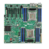
Intel W2600CR Technical Product Specification (186 pages)
Server and Workstation Board
Brand:
Intel
| Category:
Motherboard
| Size: 5.74 MB
Table of Contents
Table of Contents
3
1 Introduction
15
Chapter Outline
15
Server Board Use Disclaimer
15
2 Product Overview
16
Product Feature Set
17
Table 1. Product Feature Set
17
Main Board Connector and Component Layout
19
Figure 3. Intel ® Server Board S2600IP Major Components
20
Figure 1. Intel Server Board S2600IP
22
Figure 4. Intel ® Server Board S2600IP Rear I/O Layout
22
Main Board Rear I/O Layout
22
Table 74. Intel
22
Figure 5. Intel ® Workstation Board W2600CR Rear I/O Layout
23
Figure 6. Mounting Hole Locations (1 of 2)
24
Server Board Mechanical Drawings
24
Figure 7. Mounting Hole Locations (2 of 2)
25
Figure 8. Major Connector Pin-1 Locations (1 of 3)
26
Figure 9. Major Connector Pin-1 Locations (2 of 3)
27
Figure 10. Major Connector Pin-1 Locations (3 of 3)
28
Figure 11. Primary Side Keep-Out Zone
30
Figure 12. Primary Side Card-Side Keep-Out Zone
31
Figure 13. Second Side Keep-Out Zone
32
3 Functional Architecture
33
Figure 14. Intel ® Server Board S2600IP Functional Block Diagram
33
Processor Support
34
Processor Socket Assembly
34
Figure 15. Intel ® Workstation Board W2600CR Functional Block Diagram
34
Figure 16. Processor Socket Assembly
35
Figure 17. Processor Socket ILM
35
Processor Population Rules
36
Processor Initialization Error Summary
36
Table 2. Mixed Processor Configurations Error Summary
37
Processor Functions Overview
39
Intel ® Quickpath Interconnect
39
Integrated Memory Controller (IMC) and Memory Subsystem
40
Figure 18. Integrated Memory Controller Functional Block Diagram
40
Table 3. UDIMM Support Guidelines
41
Table 4. RDIMM Support Guidelines
42
Table 5. LRDIMM Support Guidelines
42
Table 6. DIMM Nomenclature
43
Figure 19. DIMM Slot Layout
44
Processor Integrated I/O Module (IIO)
46
Intel C600-A Chipset Functional Overview
47
Digital Media Interface (DMI)
48
PCI Express* Interface
48
Serial ATA (SATA) Controller
48
Serial Attached SCSI (SAS)/SATA (SCU) Controller
49
Ahci
49
Rapid Storage Technology
49
Table 7. Intel RAID C600 Upgrade Key Options
49
Table 75. Intel
49
Table 76. Intel
49
PCI Interface
50
Low Pin Count (LPC) Interface
50
Serial Peripheral Interface (SPI)
50
Compatibility Modules (DMA Controller, Timer/Counters, Interrupt Controller)
50
Advanced Programmable Interrupt Controller (APIC)
50
Universal Serial Bus (USB) Controllers
50
Gigabit Ethernet Controller
51
Rtc
51
Gpio
51
Enhanced Power Management
51
Manageability
51
System Management Bus (Smbus* 2.0)
51
Integrated NVSRAM Controller
52
Virtualization Technology for Directed I/O (Intel VT-D)
52
JTAG Boundary-Scan
52
Kvm/Serial over Lan (SOL) Function
52
On-Board SAS/SATA Support and Options
52
PCI Subsystem
53
Network Interface Controller
54
Network Interface
54
Table 8. Intel ® Server Board S2600Ip/Workstation Board W2600CR PCI Bus Segment Characteristics
54
I/O Module Support
55
Workstation Board W2600CR2L)
55
Figure 20. External RJ45 NIC Port LED Definition
55
SAS ROC Module Support
56
Figure 21. Supported I/O Module Options
56
HD Audio Support (Intel Workstation Board W2600CR Only)
57
Table 9. Supported Intel Integrated RAID Modules
57
USB3.0 Support (Intel ® Workstation Board W2600CR Only)
58
Figure 22. USB3.0 Discrete Host Controller Block Diagram
58
Table 10. Standard Speaker Channels
58
Ieee1394B Support (Intel ® Workstation Board W2600CR Only)
59
Figure 23. IEEE 1394B Discrete Host Controller Block Diagram
59
4 Platform Management Overview
60
Server Management Function Architecture
60
Feature Support
60
Basic and Advanced Features
62
Integrated BMC Hardware: Emulex* Pilot III
63
Table 11. Basic and Advanced Features
63
Server Management Functional Specifications
65
BMC Internal Timestamp Clock
65
Figure 24. Integrated BMC Hardware
65
System Event Log (SEL)
66
Sensor Data Record (SDR) Repository
66
Field Replaceable Unit (FRU) Inventory Device
66
BMC Beep Codes
66
Table 12. BMC Beep Codes
66
Diagnostic Interrupt (NMI) Button
67
BMC Watchdog
67
Table 13. NMI Signal Generation and Event Logging
67
Sensor Monitoring
68
Overview
68
Core Sensor List for EPSD Platforms Based Xeon Intel Xexeon Processor E5 4600/2600/2400/1600/1400 Product Families
68
BMC System Management Health Monitoring
70
Processor Sensors
70
Table 14. Supported BMC FW Health Sensor Offsets
70
Table 15. Processor Sensors
70
Table 16. Processor Status Sensor Implementation
71
Table 17. Supported ERR2 Timeout Sensor Offsets
72
Table 18. Supported CATERR Sensor Offsets
73
Thermal and Acoustic Management
74
4.4.1 Set Throttling Mode
74
4.4.2 Altitude
74
4.4.3 Set Fan Profile
74
Table 19. Support MSID Mismatch Sensor Offsets
74
4.4.4 Fan PWM Offset
75
4.4.5 Quiet Fan Idle Mode
75
4.4.6 Thermal Sensor Input for Fan Speed Control
75
Power Supply Status\Health Sensors
76
Figure 25. High-Level Fan Speed Control Process
76
Table 20. Supported Power Supply Status Sensor Offsets
76
System Event Sensor
77
Table 21. Support System Event Sensor Offsets
78
Table 22. Supported Firmware Update Status Sensor Offsets
78
Platform Management Interface
79
Channel Management
79
User Model
79
Table 23. Standard Channel Assignments
79
LAN Interface
80
Table 24. Supported RMCP+ Cipher Suites
80
Table 25. Supported RMCP+ Payload Types
81
Table 78. Intel
81
Table 26. Factory Configured PEF Table Entries
85
BMC Firmware Update
90
The BMC Firmware Release Number
90
Boot Recovery Mode
90
Force Firmware Update Jumper
91
Fast Firmware Update over USB
91
Advanced Management Feature Support
92
Enabling Advanced Management Features
92
Keyboard, Video, Mouse (KVM) Redirection
92
Table 27. Enabling Advanced Management Features
92
Media Redirection
93
Intel ® Intelligent Power Node Manager (NM)
95
Overview
95
EU Lot 6 Mode
96
5 System Security
98
BIOS Password Protection
98
Trusted Platform Module (TPM) Support
99
TPM Security BIOS
99
Physical Presence
100
TPM Security Setup Options
100
Figure 26. Setup Utility - TPM Configuration Screen
101
Intel Trusted Execution Technology
102
Table 28. Tsetup Utility - Security Configuration Screen Fields
102
6 Connector/Header Locations and Pin-Outs
104
Power Connectors
104
Main Power Connector
104
CPU Power Connectors
104
Add-In Card Power Connectors
104
Table 29. Main Power Connector Pin-Out
104
Table 30. CPU_1 Power Connector Pin-Out
104
Table 31. CPU_2 Power Connector Pin-Out
104
Front Panel Header and Connectors
105
Front Panel Header
105
Table 32. Add-In Slot Power Pin-Input ("OPT_12V_PWR")
105
Table 33. Front Panel Header Pin-Out
105
Front Panel USB Connector
106
Local Control Panel Connector
106
On Board Storage Connectors
106
SATA Connectors: 6Gbps
106
Table 34. Front Panel USB Connector Pin-Out
106
Table 35. Local Front Panel Connector Pin-Out
106
Table 36. SATA 6Gbps Connector Pin-Out
106
Multiport Mini-SAS/SATA Connectors
107
Table 37. Multiport SAS/SATA Connector Pin-Out ("SCU_0 (0-3)")
107
Table 38. Multiport SAS/SATA Connector Pin-Out ("SCU_1 (4-7)")
107
Intel ® RAID C600 Upgrade Key Connector
108
HSBP_I2C Header
108
HDD LED Header
108
Internal Type- a USB Connector
108
Table 39. Intel
108
Table 40. HSBP_I2C Header Pin-Out
108
Table 41. HDD LED Header Pin-Out
108
Table 42. Type-A USB Connector Pin-Out
108
Internal Eusb SSD Header
109
Management and Security Connectors
109
Rmm4_Lite Connector
109
RMM4_NIC Connector
109
Table 43. Eusb SSD Header Pin-Out
109
Table 44. Rmm4_Lite Connector Pin-Out
109
Table 45. RMM4_NIC Connector Pin-Out
109
TPM Connector
110
Pmbus* Connector
110
Chassis Intrusion Header
110
IPMB Connector
110
FAN Connectors
110
Table 46. TPM Connector Pin-Out
110
Table 47. Pmbus* Connector Pin-Out
110
Table 48. Chassis Intrusion Header Pin-Out
110
Table 49. IPMB Connector Pin-Out
110
CPU FAN Connector
111
System FAN Connectors
111
Serial Port and Video Connectors
111
Serial Port a Connector (DB9, for Intel ® Server Board S2600IP Only)
111
Table 50. 6-Pin System FAN Connector Pin-Out
111
Table 51. 4-Pin System FAN Connector Pin-Out
111
Table 52. CPU FAN Connector Pin-Out
111
Table 53. Serial Port a Connector Pin-Out
111
Serial Port B Connector
112
Video Connector (for Intel ® Server Board S2600IP Only)
112
Figure 27. Video Connector Pin-Out
112
Table 54. Serial Port B Connector Pin-Out
112
Table 55. Video Connector Pin-Out Details
112
Internal Video Header (for Intel ® Workstation Board W2600CR Only)
113
7 Jumper Blocks
114
Figure 28. Jumper Blocks (J1C3, J1F1, J1F2, J2F3, J2F2)
114
Table 56. Server Board Jumpers (J1C3, J1F1, J1F2, J2F3, J2F2)
114
BIOS Default and Password Reset Usage Procedure
115
Set BIOS to Default (Clearing the CMOS)
115
Clearing the Password
115
BIOS Recovery Jumper
116
Force BMC Update Procedure
116
ME Force Update Jumper
117
8 Intel Light Guided Diagnostics
119
5-Volt Stand-By LED
119
Fan Fault LED
119
CPU Fault LED
119
Figure 29. Stand by LED, Fan Fault LED and CPU Fault LED Location
120
DIMM Fault Leds
121
System ID LED, System Status LED and POST Code Diagnostic Leds
121
Figure 30. DIMM Fault Led's Location
121
Figure 31. Location of System Status, System ID and POST Code Diagnostic Leds
122
System ID LED
122
System Status LED
123
Table 57. System Status LED
123
POST Code Diagnostic Leds
124
Table 58. POST Code Diagnostic Leds
124
9 Design and Environmental Specifications
125
Products Design Specifications
125
Mtbf
125
Table 59. Server Board Design Specifications
125
Figure 2. Intel Workstation Board W2600CR
126
Table 60. Intel Server Board S2600IP MTBF Estimate
126
Table 61. Intel
126
Table 79. Intel
126
Table 80. Intel
126
Server Board Power Requirements
128
Figure 32. Power Distribution Block Diagram
128
Processor Power Support
129
Power Supply Output Requirements
129
Output Power/Currents
129
Cross Loading
129
Table 62. Intel
129
Table 63. Minimum Load Ratings
129
Standby Output
130
Voltage Regulation
130
Dynamic Loading
130
Table 64. Loading Conditions
130
Table 65.Voltage Regulation Limits
130
Table 66. Transient Load Requirements
130
Capacitive Loading
131
Grounding
131
Closed Loop Stability
131
Residual Voltage Immunity in Standby Mode
131
Common Mode Noise
131
Table 67. Capacitive Loading Conditions
131
Soft Starting
132
Zero Load Stability Requirements
132
Ripple/Noise
132
Timing Requirements
132
Figure 33. Differential Noise Test Setup
132
Table 68. Ripples and Noise
132
Figure 34. Output Voltage Timing
133
Table 69. Output Voltage Timing
133
Table 70. Turn On/Off Timing
133
Figure 35. Turn On/Off Timing (Power Supply Signals)
134
Appendix A: Integration and Usage Tips
135
Appendix B: BMC Sensor Tables
136
Table 71. Integrated BMC Core Sensors
138
Appendix C: Platform Specific BMC Appendix
161
Introduction
161
Product ID
161
IPMI Channel ID Assignments
161
ACPI S3 Sleep State Support
161
Processor Support for Intel Server Board S2600IP
161
Supported Chassis
161
Table 72. Intel Server Board S2600IP - BMC Channel Assignments
161
Chassis-Specific Sensors
162
Hot-Plug Fan Support
162
Fan Redundancy Support
162
Table 73. Intel Server Board S2600IP - Chassis-Specific Sensors
162
Fan Domain Definition
163
HSC Availability
165
Power Unit Support
166
Redundant Fans Only for Intel Server Chassis
166
Fan Fault LED Support
166
Memory Throttling Support
167
Introduction
167
Product ID
167
IPMI Channel ID Assignments
167
ACPI S3 Sleep State Support
167
Table 77. Intel Workstation Board W2600CR - BMC Channel Assignments
167
Processor Support for Intel Server Board W2600CR
168
Supported Chassis
168
Chassis-Specific Sensors
168
Hot-Plug Fan Support
168
Fan Redundancy Support
168
Board Specific Feature
168
Fan Domain Definition
168
HSC Availability
169
Power Unit Support
169
Redundant Fans Only for Intel Server Chassis
169
Fan Fault LED Support
169
Memory Throttling Support
169
Appendix D: POST Code Diagnostic LED Decoder
170
Figure 36. POST Code Diagnostic LED Decoder
170
Table 81. POST Progress Code LED Example
171
Table 82. POST Progress Codes
171
Table 83. MRC Progress Codes
173
Table 84. MRC Fatal Error Codes
174
Appendix E: POST Error Messages and Handling
176
Table 85. POST Error Codes and Messages
176
Table 86. POST Error Beep Codes
181
Table 87. Integrated BMC Beep Codes
182
Glossary
183
Reference Documents
186
Advertisement
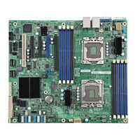
Intel W2600CR Manual (141 pages)
EPSD Platform Based on Intel Xeon Processor E5 4600/2600/2400/1600/1400 Product families
Brand:
Intel
| Category:
Motherboard
| Size: 1.21 MB
Table of Contents
Revision History
2
Table of Contents
4
1 Introduction
11
Purpose
11
Industry Standard
12
Intelligent Platform Management Interface (IPMI)
12
Baseboard Management Controller (BMC)
12
Intel ® Intelligent Power Node Manager Version 2.0
13
2 Basic Decoding of a SEL Record
14
Default Values in the SEL Records
14
Table 1. SEL Record Format
14
Table 2: Event Request Message Event Data Field Contents
17
Table 3: OEM SEL Record (Type C0H-Dfh)
18
Table 4: OEM SEL Record (Type E0H-Ffh)
19
Notes on SEL Logs and Collecting SEL Information
20
Examples of Decoding BIOS Timestamp Events
20
Example of Decoding a PCI Express* Correctable Error Events
21
Example of Decoding a Power Supply Predictive Failure Event
22
3 Sensor Cross Reference List
23
BMC Owned Sensors (GID = 0020H)
23
Table 5: BMC Owned Sensors
23
BIOS POST Owned Sensors (GID = 0001H)
34
BIOS SMI Handler Owned Sensors (GID = 0033H)
34
Table 6: BIOS POST Owned Sensors
34
Table 7: BIOS SMI Handler Owned Sensors
34
Node Manager / ME Firmware Owned Sensors (GID = 002Ch or 602Ch)
35
Table 8: Management Engine Firmware Owned Sensors
35
Microsoft* os Owned Events (GID = 0041)
36
Linux* Kernel Panic Events (GID = 0021)
36
Table 9: Microsoft* os Owned Events
36
Table 10: Linux* Kernel Panic Events
36
4 Power Subsystems
37
Threshold-Based Voltage Sensors
37
Table 11: Threshold-Based Voltage Sensors Typical Characteristics
37
Table 12: Threshold-Based Voltage Sensors Event Triggers - Description
38
Table 13: Threshold-Based Voltage Sensors - Next Steps
38
Voltage Regulator Watchdog Timer Sensor
43
Voltage Regulator Watchdog Timer Sensor - Next Steps
44
Power Unit
44
Power Unit Status Sensor
44
Table 14: Voltage Regulator Watchdog Timer Sensor Typical Characteristics
44
Table 15: Power Unit Status Sensors Typical Characteristics
45
Table 16: Power Unit Status Sensor - Sensor Specific Offsets - Next Steps
45
Power Unit Redundancy Sensor
46
Table 17: Power Unit Redundancy Sensors Typical Characteristics
46
Node Auto Shutdown Sensor
47
Table 18: Power Unit Redundancy Sensor - Event Trigger Offset - Next Steps
47
Table 19: Node Auto Shutdown Sensor Typical Characteristics
47
Power Supply
48
Power Supply Status Sensors
48
Table 20: Power Supply Status Sensors Typical Characteristics
48
Table 21: Power Supply Status Sensor - Sensor Specific Offsets - Next Steps
49
Power Supply Power in Sensors
51
Table 22: Power Supply Power in Sensors Typical Characteristics
51
Table 23: Power Supply Power in Sensor - Event Trigger Offset - Next Steps
51
Power Supply Current out % Sensors
52
Table 24: Power Supply Current out % Sensors Typical Characteristics
52
Table 25: Power Supply Current out % Sensor - Event Trigger Offset - Next Steps
52
Power Supply Temperature Sensors
53
Table 26: Power Supply Temperature Sensors Typical Characteristics
53
Table 27: Power Supply Temperature Sensor - Event Trigger Offset - Next Steps
53
Power Supply Fan Tachometer Sensors
54
Table 28: Power Supply Fan Tachometer Sensors Typical Characteristics
54
5 Cooling Subsystem
55
Fan Sensors
55
Fan Tachometer Sensors
55
Table 29: Fan Tachometer Sensors Typical Characteristics
55
Fan Presence and Redundancy Sensors
56
Table 30: Fan Tachometer Sensor - Event Trigger Offset - Next Steps
56
Table 31: Fan Presence Sensors Typical Characteristics
56
Table 32: Fan Presence Sensors - Event Trigger Offset - Next Steps
57
Table 33: Fan Redundancy Sensors Typical Characteristics
57
Table 34: Fan Redundancy Sensor - Event Trigger Offset - Next Steps
58
Temperature Sensors
59
Threshold-Based Temperature Sensors
59
Table 35: Temperature Sensors Typical Characteristics
59
Table 36: Temperature Sensors Event Triggers - Description
60
Table 37: Temperature Sensors - Next Steps
60
Thermal Margin Sensors
61
Table 38: Thermal Margin Sensors Typical Characteristics
61
Table 39: Thermal Margin Sensors Event Triggers - Description
62
Table 40: Thermal Margin Sensors - Next Steps
62
Processor Thermal Control Sensors
63
Table 41: Processor Thermal Control Sensors Typical Characteristics
63
Table 42: Processor Thermal Control Sensors Event Triggers - Description
64
Processor DTS Thermal Margin Sensors
65
Discrete Thermal Sensors
65
Table 43: Processor DTS Thermal Margin Sensors Typical Characteristics
65
Table 44: Discrete Thermal Sensors Typical Characteristics
66
Table 45: Discrete Thermal Sensors - Next Steps
66
DIMM Thermal Trip Sensors
67
Table 46: DIMM Thermal Trip Typical Characteristics
67
System Air Flow Monitoring Sensor
68
6 Processor Subsystem
69
Processor Status Sensor
69
Table 47: Process Status Sensors Typical Characteristics
69
Table 48: Processor Status Sensors - Next Steps
70
Catastrophic Error Sensor
71
Table 49: Catastrophic Error Sensor Typical Characteristics
71
Table 50: Catastrophic Error Sensor - Event Data 2 Values - Next Steps
71
CPU Missing Sensor
72
Table 51: CPU Missing Sensor Typical Characteristics
72
CPU Missing Sensor - Next Steps
73
Quick Path Interconnect Sensors
73
QPI Link Width Reduced Sensor
73
Table 52: QPI Link Width Reduced Sensor Typical Characteristics
73
QPI Correctable Error Sensor
74
Table 53: QPI Correctable Error Sensor Typical Characteristics
74
QPI Fatal Error and Fatal Error #2
75
Table 54: QPI Fatal Error Sensor Typical Characteristics
75
Table 55: QPI Fatal #2 Error Sensor Typical Characteristics
76
Processor ERR2 Timeout Sensor
77
Processor ERR2 Timeout - Next Steps
78
Processor MSID Mismatch Sensor
78
Table 56: Processor ERR2 Timeout Sensor Typical Characteristics
78
Processor MSID Mismatch Sensor - Next Steps
79
Table 57: Processor MSID Mismatch Sensor Typical Characteristics
79
7 Memory Subsystem
80
Memory RAS Configuration Status
80
Table 58: Memory RAS Configuration Status Sensor Typical Characteristics
80
Table 59: Memory RAS Configuration Status Sensor - Event Trigger Offset - Next Steps
81
Memory RAS Mode Select
82
Table 60: Memory RAS Mode Select Sensor Typical Characteristics
82
Mirroring Redundancy State
83
Table 61: Mirroring Redundancy State Sensor Typical Characteristics
83
Mirroring Redundancy State Sensor - Next Steps
84
Sparing Redundancy State
84
Table 62: Sparing Redundancy State Sensor Typical Characteristics
85
Sparing Redundancy State Sensor - Next Steps
86
ECC and Address Parity
86
Memory Correctable and Uncorrectable ECC Error
86
Table 63: Correctable and Uncorrectable ECC Error Sensor Typical Characteristics
86
Memory Address Parity Error
88
Table 65: Address Parity Error Sensor Typical Characteristics
88
8 PCI Express* and Legacy PCI Subsystem
91
PCI Express* Errors
91
Legacy PCI Errors
91
Table 66: Legacy PCI Error Sensor Typical Characteristics
91
PCI Express* Fatal Errors and Fatal Error #2
92
Table 67: PCI Express* Fatal Error Sensor Typical Characteristics
92
Table 68: PCI Express* Fatal Error #2 Sensor Typical Characteristics
93
PCI Express* Correctable Errors
94
Table 69: PCI Express* Correctable Error Sensor Typical Characteristics
95
9 System BIOS Events
97
System Events
97
System Boot
97
Timestamp Clock Synchronization
97
Table 70: System Event Sensor Typical Characteristics
98
System Firmware Progress (Formerly Post Error)
99
System Firmware Progress (Formerly Post Error) - Next Steps
99
Table 71: POST Error Sensor Typical Characteristics
99
Table 72: POST Error Codes
100
10 Chassis Subsystem
107
Physical Security
107
Chassis Intrusion
107
LAN Leash Lost
107
Table 73: Physical Security Sensor Typical Characteristics
107
FP (NMI) Interrupt
108
Table 74: Physical Security Sensor Event Trigger Offset - Next Steps
108
FP (NMI) Interrupt - Next Steps
109
Table 75: FP (NMI) Interrupt Sensor Typical Characteristics
109
Button Sensor
110
Table 76: Button Sensor Typical Characteristics
110
11 Miscellaneous Events
111
IPMI Watchdog
111
Table 77: IPMI Watchdog Sensor Typical Characteristics
111
SMI Timeout
112
Table 78: IPMI Watchdog Sensor Event Trigger Offset - Next Steps
112
Table 79: SMI Timeout Sensor Typical Characteristics
112
SMI Timeout - Next Steps
113
System Event Log Cleared
113
Table 80: System Event Log Cleared Sensor Typical Characteristics
113
System Event - PEF Action
114
System Event - PEF Action - Next Steps
114
Table 81: System Event - PEF Action Sensor Typical Characteristics
114
BMC Watchdog Sensor
115
BMC Watchdog Sensor - Next Steps
115
Table 82: BMC Watchdog Sensor Typical Characteristics
115
BMC FW Health Sensor
116
BMC FW Health Sensor - Next Steps
116
Table 83: BMC FW Health Sensor Typical Characteristics
116
Firmware Update Status Sensor
117
Table 84: Firmware Update Status Sensor Typical Characteristics
117
Add-In Module Presence Sensor
118
Add-In Module Presence - Next Steps
118
Table 85: Add-In Module Presence Sensor Typical Characteristics
118
Intel ® Xeon Phi ™ Coprocessor Management Sensors
119
Intel ® Xeon Phi ™ Coprocessor (MIC) Thermal Margin Sensors
119
Intel ® Xeon Phi ™ Coprocessor (MIC) Status Sensors
119
Table 86: MIC Status Sensors - Typical Characteristics
119
12 Hot-Swap Controller Backplane Events
121
HSC Backplane Temperature Sensor
121
Table 87: HSC Backplane Temperature Sensor Typical Characteristics
121
Hard Disk Drive Monitoring Sensor
122
Table 88: HSC Backplane Temperature Sensor - Event Trigger Offset - Next Steps
122
Table 89: Hard Disk Drive Monitoring Sensor Typical Characteristics
122
Hot-Swap Controller Health Sensor
123
Table 90: Hard Disk Drive Monitoring Sensor - Event Trigger Offset - Next Steps
123
Table 91: HSC Health Sensor Typical Characteristics
123
HSC Health Sensor - Next Steps
124
13 Manageability Engine (ME) Events
125
ME Firmware Health Event
125
ME Firmware Health Event - Next Steps
125
Table 92: ME Firmware Health Event Sensor Typical Characteristics
125
Table 93: ME Firmware Health Event Sensor - Next Steps
126
Node Manager Exception Event
127
Node Manager Exception Event - Next Steps
127
Table 94: Node Manager Exception Sensor Typical Characteristics
127
Node Manager Health Event
128
Table 95: Node Manager Health Event Sensor Typical Characteristics
128
Node Manager Health Event - Next Steps
129
Node Manager Operational Capabilities Change
130
Table 96: Node Manager Operational Capabilities Change Sensor Typical Characteristics
130
Node Manager Operational Capabilities Change - Next Steps
131
Node Manger Alert Threshold Exceeded
132
Table 97: Node Manager Alert Threshold Exceeded Sensor Typical Characteristics
132
Node Manger Alert Threshold Exceeded - Next Steps
133
14 Microsoft Windows* Records
134
Boot up Event Records
134
Table 98: Boot up Event Record Typical Characteristics
134
Table 99: Boot up OEM Event Record Typical Characteristics
135
Shutdown Event Records
136
Table 100: Shutdown Reason Code Event Record Typical Characteristics
136
Table 101: Shutdown Reason OEM Event Record Typical Characteristics
136
Table 102: Shutdown Comment OEM Event Record Typical Characteristics
137
Bug Check / Blue Screen Event Records
138
Table 103: Bug Check/Blue Screen - os Stop Event Record Typical Characteristics
138
Table 104: Bug Check/Blue Screen Code OEM Event Record Typical Characteristics
139
15 Linux* Kernel Panic Records
140
Table 105: Linux* Kernel Panic Event Record Characteristics
140
Table 106: Linux* Kernel Panic String Extended Record Characteristics
141
Advertisement
Related Products
Intel WX58BP - Workstation Board Motherboard
Intel WX58BPR
Intel WSAP5000 - PRO/Wireless 5000 LAN Access Point
Intel WEAP2011BJP
Intel Server Configuration Wizard Utility
Intel WEAP2011EU
Intel WEAP2011SG
Intel WEAP2011EO
Intel WM3B2100
Intel WDAP5000
Intel Categories
Motherboard
Computer Hardware
Server
Server Board
Desktop
More Intel Manuals
Login
Sign In
OR
Sign in with Facebook
Sign in with Google
Upload manual
Upload from disk
Upload from URL