Precor P10 Operating And Maintaining
Precor p10 console operating and maintaining
Hide thumbs
Also See for P10:
- Operating and maintaining (112 pages) ,
- Operating and maintaining (60 pages) ,
- Service bulletin (2 pages)
Table of Contents
Advertisement
Quick Links
Advertisement
Chapters
Table of Contents

Related Manuals for Precor P10


Summary of Contents for Precor P10
- Page 1 Operating and Maintaining the P10 Console...
- Page 3 Operating and Maintaining the P10 Console...
- Page 4 Preva Business Suite, the accompanying printed materials, any copies of such software, and all data collected via the Preva Business Suite, are exclusively owned by Precor or its suppliers, as the case may be. Precor is widely recognized for its innovative, award-winning designs of exercise equipment.
-
Page 5: Important Safety Instructions
Note: This product is intended for commercial use. The display apparatus (hereinafter referred to as the console) is intended to be shipped with new Precor exercise equipment (hereinafter referred to as the base unit). It is not packaged for individual sale. -
Page 6: Safety Precautions
Operating and Maintaining the P10 Console Safety Precautions Always follow basic safety precautions when using this equipment to reduce the chance of injury, fire, or damage. Other sections in this manual provide more details of safety features. Be sure to read these sections and observe all safety notices. - Page 7 Important Safety Instructions Never leave the equipment unattended when it is plugged in. Unplug the equipment from its power source when it is not in use, before cleaning it, and before providing authorized service. Note: The optional power adapter is considered a power source for self-powered equipment.
- Page 8 Operating and Maintaining the P10 Console SPACING—The below minimum spacing recommendations are based on a combination of the ASTM (U.S.) voluntary standards and EN (European) regulations as of October 1, 2012, for access, passage around, and emergency dismount: –...
- Page 9 350 pounds (160 kg). Use the equipment only for its intended purpose as described in this manual. Do not use accessory attachments that are not recommended by Precor. Such attachments may cause injuries. Do not operate the equipment where aerosol (spray) products are being used or where oxygen is being administered.
-
Page 10: Hazardous Materials And Proper Disposal
The batteries within self-powered equipment contain materials that are considered hazardous to the environment. Federal law requires proper disposal of these batteries. If you plan to dispose of your equipment, contact Precor Commercial Products Customer Support for information regarding battery removal. Refer to Obtaining Service. -
Page 11: Regulatory Notices For Cardiovascular Exercise Equipment
Exercise Equipment The regulatory information in this section applies to the exercise equipment and its control console. Safety Approvals for Cardiovascular Equipment Precor equipment has been tested and found to comply with the following applicable safety standards. Cardiovascular Type Equipment: ... - Page 12 Operating and Maintaining the P10 Console Industry Canada This device complies with RSS-210:2007 of the Spectrum Management & Telecommunications Radio Standards Specification. Operation is subject to the following two conditions: (1) this device may not cause harmful interference, and (2) this device must accept any interference received, including interference that may cause undesired operation.
-
Page 13: Electrical Recommendations: 120 V And 240 V Treadmills
You should have received a power cable that meets your local electrical code requirements along with the equipment. Precor treadmills must be connected to a 20 amp individual branch circuit that can be shared only with one PVS. If you need additional help with the power connections contact your Precor authorized dealer. -
Page 14: Electrical Recommendations: All Equipment Excluding Treadmills
Do not attempt to service the equipment except for maintenance tasks. If any items are missing, contact your dealer. For more information regarding customer support numbers or a list of Precor authorized service centers, visit the Precor web site at http://www.precor.com. -
Page 15: Table Of Contents
Club Parameters ................... 21 Viewing the Informational Displays ..........25 User ID Entry with CSAFE Equipment ........... 30 Introducing Users to the P10 Console ........31 Using the Touch Heart Rate Feature ..........31 Using a Chest Strap Transmitter ............ 33 Using the Treadmill Safety Clip ............ - Page 16 Operating and Maintaining the P10 Console Starting a Workout ..............37 Starting a Preset Programmed Workout ........38 Pausing and Resuming an Exercise Session ........ 38 Ending a Session ................. 39 Workouts ....................41 Maintenance ................49 Cleaning the Console and Display ..........50 Checking and Resetting the Active Status Light (Treadmill Only) ................
-
Page 17: Getting Started
Chapter Getting Started The P10 console offers administrators the ability to set default values that meet their specific needs. These values include items like language, units of measure, and setting a maximum allowed workout time for each piece of equipment. - Page 18 CAUTION: The internal cable kit must be installed by authorized service personnel. Do not attempt installation on your own as you could void the Precor Limited Warranty. For more information, refer to Obtaining Service. Important: If this equipment includes a P80 console, the optional...
-
Page 19: Identifying Parts Of The Console
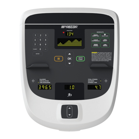
The following figure provides information about the console keys. The number and actions of the console keys may differ slightly depending on the type of equipment. Figure 4: P10 console keys Table 1. Parts of the console Number Name Details... - Page 20 Operating and Maintaining the P10 Console Number Name Details Workouts Examples of workouts: • Manual • Heart Rate • Interval • Weight Loss • Variety • Performance Pause Use to pause or end a workout session. OK and Up/Down Use to navigate options and settings.
- Page 21 Chapter Setting Up the Console Use the System mode to configure settings in ways that benefit your users and your facility. The System menu is visible only to administrators and registered service technicians. Changes made to these settings are saved to the fitness equipment.
- Page 22 Operating and Maintaining the P10 Console CAUTION: If you change the Unit of Measure display on the treadmill, check the speed setting to verify that it is correct. To view the Club Settings: At the Welcome banner, press Pause. 2. Press the following number keys in sequence to enter the...
-
Page 23: Setting Up The Console
Setting Up the Console Club Parameters Use the following information to customize the equipment for your setting. Note: When you make changes to the club parameters, the new settings replace the factory default settings. Safety Code (Treadmill only) Value: Enabled or Disabled (Default: Disabled) When the equipment is shipped from the factory, the safety code protection feature is disabled. - Page 24 Operating and Maintaining the P10 Console Set Max Workout Time (All Equipment) Value Range: 1 to 240 minutes (Default: 60 minutes) You can set a maximum workout time per session. Choose a time limit between 1 and 240 minutes, or select No Limit if you do not want to set a time limit.
- Page 25 Setting Up the Console Set Speed Limit (Treadmill only) Value Range: Full speed range of equipment (Default: Maximum speed) This setting limits how fast the running belt moves and, consequently, the number of speed settings that are available to the user. Use it to set the maximum speed that a user can enter when using the equipment.
- Page 26 Operating and Maintaining the P10 Console Autostop Configure (Treadmill only) Value: On or Off (Default: On) Set to On to bring the treadmill to a gradual stop when no user is on the equipment. This can occur if a user steps off the equipment during a workout and does not turn it off.
-
Page 27: Viewing The Informational Displays
Setting Up the Console Viewing the Informational Displays Information Display settings are values that provide you with information about the equipment. Types of information contained in this setting group include, an event (error) log, software and equipment serial numbers, and usage information. - Page 28 Operating and Maintaining the P10 Console Use the following table to set up customized Informational Display values. Table 3. Informational Displays values Product Value Information provided ODOMETER Correlates to the type of equipment and the standard of units, U.S. or Metric, selected in the programs.
- Page 29 Setting Up the Console Product Value Information provided UPPER BASE Displays the upper base application SW PART software version. NUMBER LOWER BASE Displays the lower application SW PART software version. NUMBER METRICS Displays the software number on the BOARD Metrics Board. SERIAL Displays the model and type of NUMBER...
- Page 30 Operating and Maintaining the P10 Console The following table contains a list of events detectable by the software. Table 4. Event log numbers and descriptions Event Description of Event Number Upper PCA memory location event RAM location event EEPROM checksum event...
- Page 31 Setting Up the Console Event Description of Event Number Communication event upper board to lower board Incorrect communications event lower board to upper board Excessive AC input current (instantaneous; treadmill only) Excessive AC input current (sustained / circuit breaker trip protection; treadmill only) E-STOP error (treadmill only) Lift motion not detected Lift position value out of range...
-
Page 32: User Id Entry With Csafe Equipment
Operating and Maintaining the P10 Console Event Description of Event Number Phase C missing (incline control; treadmill only) Phase A or B missing (speed control; treadmill only) Phase C missing (speed control; treadmill only) No dynamic break resistor detected, or dynamic break... - Page 33 The P10 console offers an easy-to-follow display and multiple workouts to help people meet their exercise needs. Important: Please review the following sections in this guide with your users before allowing them to use the fitness equipment: ...
- Page 34 If the touch heart rate feature does not work for you, Precor recommends that you use a chest transmitter strap. Heart Rate Target Zones High...
-
Page 35: Introducing Users To The P10 Console
Introducing Users to the P10 Console Using a Chest Strap Transmitter WARNING Signals used by the chest strap transmitter (or heart rate strap) may interfere with pacemakers or other implanted devices. Consult your physician and the manufacturers of your chest strap transmitter and implanted device before using a chest strap transmitter. -
Page 36: Using The Treadmill Safety Clip
Operating and Maintaining the P10 Console Using the Treadmill Safety Clip The treadmill is equipped with three different stop functions, which behave as follows: If the user … Then the And the console … treadmill belt … Pulls on the lanyard... - Page 37 Introducing Users to the P10 Console Instruct users on how important it is to use the safety clip while exercising on the treadmill, and demonstrate how they should attach it to their clothing near the waistline. If the restart switch trips during exercise, perform the following steps: Reattach the safety clip if necessary.
-
Page 38: Treadmill Auto Stop™ (Automatic Stop) Function
Operating and Maintaining the P10 Console Treadmill Auto Stop™ (Automatic Stop) Function Important: The default setting for this feature is ON. An administrator can turn off this feature in the System Settings; however, Precor recommends it remain ON. The Auto Stop™ (Automatic Stop) feature is designed to bring the treadmill to a gradual stop when it is not in use. -
Page 39: Starting A Workout
Chapter Starting a Workout CAUTION: If you are using a treadmill, be sure to attach the security clip to your clothing before starting your workout. The equipment is in the Welcome state when the words SELECT A WORKOUT OR PRESS QUICKSTART TO BEGIN scroll across the scrolling text display. -
Page 40: Starting A Preset Programmed Workout
Operating and Maintaining the P10 Console Starting a Preset Programmed Workout Preset workouts are a great way to tailor your workouts to your fitness goals, stay challenged, and add variety to your sessions. These workouts are arranged in the following categories: ... -
Page 41: Ending A Session
Starting a Workout Ending a Session Cooling down is an important aspect of your workout because it helps reduce muscle stiffness and soreness by transporting excess lactic acid out of the working muscles. In addition, a three to five minute cool down allows your heart rate to return to its normal, resting state. - Page 42 Operating and Maintaining the P10 Console Three different types of metrics are captured during a workout. Controlled Metrics can be set and changed. They include: Resistance Level (AMT, EFX, bike) Speed (treadmill) Incline (treadmill) Crossramp (EFX) Current Performance Metrics describe the intensity of a workout in real time.
-
Page 43: Workouts
By keeping your muscles guessing, you’ll keep your energy use up, promoting faster weight loss and better conditioning. The workouts in the following table are available on units equipped with the P10 console. Table 6. P10 Console Workouts Console Key Workout AMT EFX Treadmill Bike ✓... - Page 44 Operating and Maintaining the P10 Console Weight Loss Key Pressing the Weight Loss key scrolls through the workouts that are designed to encourage weight loss and aerobic conditioning. ® The American College of Sports Medicine recommends that adults get at least 30–60 minutes of moderately intense exercise five days a week.
- Page 45 Starting a Workout Performance Key Press the Performance key repeatedly to select a workout that conditions and tests the body’s muscular and aerobic performance. Note: On treadmills, a fitness test option is also available. A technician at the fitness facility must activate the fitness test before you can use it.
- Page 46 Operating and Maintaining the P10 Console Cross Training Workouts This workout delivers true training variety and muscular engagement by adjusting the resistance and incline continuously to simulate the dynamic terrain of an outdoor run. The CrossRamp setting is preprogrammed in each of these workouts, but you can change it or the resistance setting at any time.
- Page 47 Starting a Workout The treadmill ends the test prematurely if any of the following things happen: The equipment cannot detect your heartbeat. Your heart rate exceeds 85% of your maximum safe rate for 15 seconds or more. Your heart rate changes too quickly.
- Page 48 Operating and Maintaining the P10 Console Variety Key Pressing the Variety key selects a random or specialized workout designed for the fitness equipment you are using. Random Variety (for both the muscles and the mind) is the key to continued success for every exercise goal. The Random workout delivers a different training profile every time you select it.
- Page 49 Starting a Workout Interval Key Interval workouts help exercisers improve strength, endurance, aerobic and anaerobic fitness. They alternate short bursts of high intensity activity with recovery periods. Pressing the Interval key selects the available interval workout. Note: On the AMT, two different interval workouts are available.
- Page 50 Operating and Maintaining the P10 Console Manual Key The workout available through the Manual key motivates you by allowing you to define and track your exertion levels throughout your exercise session. Training tip: As you progress through your workout, each segment of the profile reflects the last change you made to the intensity settings.
-
Page 51: Maintenance
To keep the equipment functioning properly, perform the minor maintenance tasks in this section at the intervals suggested. Failure to maintain the equipment as described in this section could void the Precor Limited Warranty. DANGER To reduce the risk of electrical shock, always... -
Page 52: Cleaning The Console And Display
Simple Green® (for more information, visit www.simplegreen.com). Important: Do not use any acidic cleaners. Doing so will weaken the paint or powder coatings and void the Precor Limited Warranty. Never pour water or spray liquids directly on the console or console’s screen. -
Page 53: Checking And Resetting The Active Status Light (Treadmill Only)
Maintenance Checking and Resetting the Active Status Light (Treadmill Only) Experience Series treadmills manufactured after June 2014 include many improvements in design, function, and usability. One of those improvements is the status indicator light at the front of the treadmill hood, which gives a club owner or technician an easy way to check up on the condition of the treadmill. - Page 54 If the error occurs taken itself out of again, check the console’s service. event log for more information, then contact Precor Customer Support. Important: Contact Precor Customer Support before running any of the diagnostic tests on the Hardware Validation menu.
- Page 55 Maintenance To review and reset the status of the treadmill: At the Welcome banner, press the Pause key, then enter the following digits on the keypad: 5 1 7 6 5 7 6 1 2. Use the up and down arrow keys to scroll through the menu names until HARDWARE VALIDATION appears.
-
Page 56: Changing The Belt (Amt Only)
BELTS CHANGE REQUIRED scrolls continuously on the Welcome screen. The input keys are not functional and the user cannot enter values or begin a workout until the belts are changed. Please contact Precor Customer Support to schedule a belt change. - Page 57 Notes Notes:...
- Page 58 Operating and Maintaining the P10 Console Notes:...
- Page 60 Precor Incorporated P10 OM 302291-102 rev B, en 20031 142nd Avenue NE June 2014 P.O. Box 7202 Woodinville, WA USA 98072-4002...
- Page 61 Assembling and Maintaining TRM 800-Series Treadmills...
- Page 62 ...
- Page 63 Assembling and Maintaining TRM 800-Series Treadmills...
- Page 64 Preva Business Suite, the accompanying printed materials, any copies of such software, and all data collected via the Preva Business Suite, are exclusively owned by Precor or its suppliers, as the case may be. Precor is widely recognized for its innovative, award-winning designs of exercise equipment.
- Page 65 Note: This product is intended for commercial use. The display apparatus (hereinafter referred to as the console) is intended to be shipped with new Precor exercise equipment (hereinafter referred to as the base unit). It is not packaged for individual sale.
- Page 66 Assembling and Maintaining TRM 800-Series Treadmills Safety Precautions Always follow basic safety precautions when using this equipment to reduce the chance of injury, fire, or damage. Other sections in this manual provide more details of safety features. Be sure to read these sections and observe all safety notices.
- Page 67 Important Safety Instructions Care should be taken when mounting or dismounting the equipment. For Treadmills: Do not use typing or web surfing features while walking at speeds that exceed a slow and relaxed leisurely pace. Always stabilize yourself by holding a stationary handle bar while using typing or web surfing features.
- Page 68 Assembling and Maintaining TRM 800-Series Treadmills SPACING—The below minimum spacing recommendations are based on a combination of the ASTM (U.S.) voluntary standards and EN (European) regulations as of October 1, 2012, for access, passage around, and emergency dismount: – Treadmills—a minimum of 0.5 m (19.7 in.) on each side of the treadmill and 2 m (78 in.) behind the machine.
-
Page 69: Safety Code
350 pounds (160 kg). Use the equipment only for its intended purpose as described in this manual. Do not use accessory attachments that are not recommended by Precor. Such attachments may cause injuries. Do not operate the equipment where aerosol (spray) products are being used or where oxygen is being administered. -
Page 70: Educating Users
The batteries within self-powered equipment contain materials that are considered hazardous to the environment. Federal law requires proper disposal of these batteries. If you plan to dispose of your equipment, contact Precor Commercial Products Customer Support for information regarding battery removal. Refer to Obtaining Service. -
Page 71: Product Recycling And Disposal
Important Safety Instructions Product Recycling and Disposal This equipment must be recycled or discarded according to applicable local and national regulations. Product labels, in accordance with European Directive 2002/96/EC concerning waste electrical and electronic equipment (WEEE), determine the framework for the return and recycling of used equipment as applicable throughout the European Union. -
Page 72: Regulatory Notices For The Rfid Module
Assembling and Maintaining TRM 800-Series Treadmills Regulatory Notices for the RFID Module When equipped with a control console as described in this document, this equipment may include a radio-frequency identification (RFID) module. The RFID module has been certified to operate at temperatures between -20°C and 85°C (-4°F and 185°F). - Page 73 Important Safety Instructions Industry Canada This device complies with RSS-210:2007 of the Spectrum Management & Telecommunications Radio Standards Specification. Operation is subject to the following two conditions: (1) this device may not cause harmful interference, and (2) this device must accept any interference received, including interference that may cause undesired operation.
-
Page 74: Regulatory Notices For Cardiovascular Exercise Equipment
Exercise Equipment The regulatory information in this section applies to the exercise equipment and its control console. Safety Approvals for Cardiovascular Equipment Precor equipment has been tested and found to comply with the following applicable safety standards. Cardiovascular Type Equipment: ... -
Page 75: Treadmill Grounding Instructions
This plug must be inserted into an outlet that is properly installed and grounded in accordance with all local codes and ordinances. Failure to ground the treadmill properly may void the Precor Limited Warranty. DANGER Improper connection of the grounding conductor can result in a risk of electric shock. - Page 76 You should have received a power cable that meets your local electrical code requirements along with the equipment. Precor treadmills must be connected to a 20 amp individual branch circuit that can be shared only with one PVS. If you need additional help with the power connections contact your Precor authorized dealer.
-
Page 77: Obtaining Service
Do not attempt to service the equipment except for maintenance tasks. If any items are missing, contact your dealer. For more information regarding customer support numbers or a list of Precor authorized service centers, visit the Precor web site at http://www.precor.com. -
Page 78: Obtaining Updated Documentation
Assembling and Maintaining TRM 800-Series Treadmills Obtaining Updated Documentation Current Precor product documentation is available at http://www.precor.com/productmanuals. You may want to check in for updated information from time to time. - Page 79 Completing the Console Installation (P80) ......... 45 Positioning the Console (P30 and P10) ........46 Connecting Cables (P30 and P10) ..........47 Completing the Console Installation (P30 and P10) ....50 Reassembling the Treadmill Fairing ..........51 Plugging In the Power Cord .............. 53 Checking Treadmill Alignment and Adjusting the Running Belt ................
- Page 80 Assembling and Maintaining TRM 800-Series Treadmills Maintenance ................57 Daily Cleaning ..................57 Daily Inspection .................. 58 Weekly Maintenance ................. 61 Monthly Maintenance ..............62 Checking the Alignment of the Running Belt ......63 Adjusting the Running Belt .............. 64 Storing the Chest Strap ..............65 Moving the Equipment ..............
-
Page 81: Assembling The Treadmill
Chapter Assembling the Treadmill Important: The instructions in the following procedures are described from the perspective of a person standing directly in front of the equipment (that is, on the opposite side of the control console from a person using the equipment). These descriptions may not match the names of certain parts in the parts list, because such parts are named relative to the back of the equipment. -
Page 82: Installation Requirements
CAUTION: Do not use a non-grounded outlet or transformer. Do not remove or otherwise bypass the plug with an adapter. Electrical damage can occur and void the Precor Limited Warranty if the treadmill is connected to an improper power source. - Page 83 The hardware kit shipped with this equipment contains the fasteners and other hardware components shown in the following table. Before you begin assembly, make sure that your hardware kit is complete. If not, please contact Precor Customer Support. Fasteners Quantity ³...
-
Page 84: Unpacking The Cables
Assembling and Maintaining TRM 800-Series Treadmills Corner cover (2) Access cover (2) Note: Retrieve the cables and other hardware shipped with the console before you begin installation. Unpacking the Cables To connect the console to the base unit, you may need up to four cables, as follows: ... -
Page 85: Assembling The Frame
Assembling the Treadmill Assembling the Frame DANGER Make sure that the treadmill is not connected to any power source before you begin the following procedures. Each of the upright supports on this treadmill has two internal channels: one to provide structural support and one to contain the cables. - Page 86 Assembling and Maintaining TRM 800-Series Treadmills To begin assembly of the frame: Gently flex the bottom front edge of the treadmill hood forward and around the bracket at the front of the treadmill base. Lift the hood off of the treadmill base and set it aside.
- Page 87 Assembling the Treadmill 6. Pull the data cable gently upward through the upright support to remove any extra cable from the base of the treadmill. Drape the upper end of the data cable over the inside edge of the upright support, using tape to hold it in place if necessary.
- Page 88 Assembling and Maintaining TRM 800-Series Treadmills 2. Connect the new power harness as shown in the following figure and table. Figure 7: P80 power harness connection points Table 1. P80 power harness connections Location Connector Drive input connector Brown lead with quick-connect terminal Blue lead with quick-connect terminal Green and yellow lead with quick-connect terminal AC input connector for DC power supply...
- Page 89 Assembling the Treadmill To install the accessory jack panel (treadmills with P80 consoles only): Remove the two #10 x ¹ ₂-inch Phillips-head machine screws securing the blank plate at the right front corner of the treadmill, as shown in the following figure. Discard the blank plate.
- Page 90 Assembling and Maintaining TRM 800-Series Treadmills 4. Pass the lower end of the Ethernet cable through the right-hand grommet and snap it into the eight-pin modular coupler installed in the jack panel. 5. Fit the lower ends of any optional console cables into the notch in the upper edge of the jack panel.
- Page 91 Assembling the Treadmill To attach the treadmill fairing and finish installing the cables: Detach the six ¹ ₄-inch × ³ ₄-inch self-tapping panhead screws securing the back cover on the treadmill fairing, then remove the back cover. Set the back cover and the six screws aside to be reinstalled later.
- Page 92 Assembling and Maintaining TRM 800-Series Treadmills 3. Route the upper end of the base unit data cable from the top of the upright support on your left (shown as position 1 in the following figure) through the spacing ring (position 2) and up through the cable channel on your left (position 3).
- Page 93 The Precor Limited Warranty does not cover cables damaged by improper installation. 5. Secure the fairing assembly using six ³ ₈-inch × 1-inch buttonhead screws and six ³...
-
Page 94: Completing Assembly
Assembling and Maintaining TRM 800-Series Treadmills Completing Assembly After the upright supports and the fairing are in place, tighten the upright support fasteners and replace the hood as described in the following procedures. WARNING Before you finish assembling the treadmill base, examine the electrical bleed line between the belt motor and the frame. - Page 95 Assembling the Treadmill To secure the fasteners: Important: The figure at the end of this procedure shows only one side of the treadmill. Be sure to complete each step on both sides before you proceed to the following step. Fully tighten the four screws that secure the sides of the upright supports to the treadmill base, as shown in the following figure.
- Page 96 Assembling and Maintaining TRM 800-Series Treadmills To complete assembly of the treadmill base: Attach a corner cover to each of the lower front corners of the treadmill. Insert the two hooks on the inside of each corner cover into the rectangular openings in the treadmill frame, then rotate the cover into position.
-
Page 97: Leveling The Unit
Assembling the Treadmill 5. Position the hood so that its screw holes line up correctly with the holes on the base of the treadmill. Figure 18: Hood installation and attachment 6. Insert one ¹ ₄-inch × ³ ₄-inch panhead self-tapping screw into each of the two side holes. - Page 98 Assembling and Maintaining TRM 800-Series Treadmills To level the treadmill: Place a bubble level across the running belt to see whether the treadmill is level. Figure 19: Bubble level placement on running belt If the treadmill … Then … Is level Make sure the jam nuts on the adjustable feet are tightened securely, then skip to the next procedure.
-
Page 99: Installing The Console
Chapter Installing the Console To make installation easier, all Precor Experience Series consoles use the same mounting hardware and connector locations whenever possible. The installation sequence for any of them is as follows: Threading the console cable assembly ... -
Page 100: Positioning The Console (P80)
Assembling and Maintaining TRM 800-Series Treadmills Positioning the Console (P80) Earlier in the installation, you threaded the necessary cables through the frame of the base unit and out the passthrough opening in the console mount. As you line up the back plate on the console with the console mount, you must make sure that the console cable assembly passes correctly through the openings in both components. -
Page 101: Connecting Cables (P80)
Installing the Console Connecting Cables (P80) After the console has been seated, separate the individual cables out of the end of the console cable assembly and attach them to the appropriate circuit connectors inside the console. Refer to the following diagram and table to identify the cables and connectors. - Page 102 Assembling and Maintaining TRM 800-Series Treadmills Table 2. P80 internal cable connections Cable Connector Type Circuit Connector Location Ethernet (LAN) Eight-contact modular, on round black cable TV in F-type coaxial Power Two-contact plug, polarized and latched Data from base Eight-contact modular, on unit flat gray cable Heart rate sensors Four-contact strip, keyed...
- Page 103 Installing the Console Connecting the Television Cable The console’s television tuner is mounted inside the console’s back plate. The tuner includes a short cable adapter that allows the television cable to be connected outside the back plate. To connect the television cable: Pull the cable out through the lower right corner of the back plate.
- Page 104 Assembling and Maintaining TRM 800-Series Treadmills Connecting the Ethernet and Base Unit Data Cables Both the Ethernet and base unit data cables pass through the cutaway opening at the upper right corner of the back plate and connect to nearby modular jacks in the console. Because of this, it is important to exercise caution when connecting the cables.
- Page 105 Installing the Console Connecting the Heart Rate Sensor Cable The heart rate sensor cable passes through the cutaway opening at the upper left corner of the back plate, then down to the small circuit board at the lower left of the console. The following illustration shows how the cable should look once it is installed.
- Page 106 Assembling and Maintaining TRM 800-Series Treadmills Connecting the Power Cable Route the power cable through the cutaway opening at the upper left corner of the back plate. In the nearby opening within the steel console framework, locate the socket that matches the power cable plug and connect the power cable to it.
-
Page 107: Completing The Console Installation (P80)
Installing the Console Completing the Console Installation (P80) Before you complete the final installation steps, double-check the connections you have made. Make sure that all cables are fully and securely connected, and that any unneeded cables are tied back properly. To complete the installation: Feed any extra cable back into the treadmill fairing. -
Page 108: Positioning The Console (P30 And P10)
Assembling and Maintaining TRM 800-Series Treadmills Positioning the Console (P30 and P10) Earlier in the installation, you threaded the necessary cables through the frame of the base unit and out the passthrough opening in the console mount. As you line up the back plate... -
Page 109: Connecting Cables (P30 And P10)
Installing the Console Connecting Cables (P30 and P10) Important: Pass all cables through the semicircular opening just above the console mount, as shown in the following figure. Do not attempt to route any cables through other openings or through the steel channel above the mount. - Page 110 Refer to the following diagram and table to identify the cables and connectors. Important: All cables must pass through the opening in the center of the console mount. Figure 28: Cable connections, P30 and P10 consoles...
- Page 111 Installing the Console Table 3. P30 and P10 internal cable connections Cable Connector Type Circuit Connector Location Safety key Six-contact strip, keyed (treadmills only) Data from base Eight-contact modular, on unit flat gray cable Heart rate sensors Four-contact strip, keyed...
-
Page 112: Completing The Console Installation (P30 And P10)
Assembling and Maintaining TRM 800-Series Treadmills Completing the Console Installation (P30 and P10) Before you complete the final installation steps, double-check the connections you have made. Make sure that all cables are fully and securely connected, and that any unneeded cables are tied back properly. -
Page 113: Reassembling The Treadmill Fairing
Installing the Console 4. Line up the two small tabs at the bottom of the console’s back cover with the slots at the bottom of the console case. Insert the tabs into the slots. 5. Insert the two #8–32 × ¹ ₂-inch Phillips-head screws that you removed earlier into the holes at the top edge of the console’s back cover. - Page 114 Assembling and Maintaining TRM 800-Series Treadmills 4. Repeat steps 2 and 3 to install the other access cover, then tighten all four screws securely using a ⁵ ₃₂-inch hex wrench. Figure 31: Access panel attachment 5. Insert the edge of the rear cover into the lower edge of the fairing.
-
Page 115: Plugging In The Power Cord
Do not plug the unit into a power transformer in an attempt to adjust the voltage requirements. Failure to follow these instructions might damage the unit and void the Precor Limited Warranty. After assembly is complete, plug the power cord into an appropriate outlet. -
Page 116: Checking Treadmill Alignment And Adjusting The Running Belt
Running Belt and Adjusting the Running Belt in the Maintenance chapter. Breaking In the Equipment Precor equipment does not require an actual break-in period. However, moving components such as belts, gears, and bearings can settle while the equipment is being stored or shipped. -
Page 117: Verifying That The Heart Rate Display Is Operational
Installing the Console Verifying That the Heart Rate Display Is Operational To verify that the heart rate display is operational: Begin exercising on the equipment. 2. Grasp both touch-sensitive handlebars. Note: The heart rate is read within ten seconds. During that time, the heart on the display flashes. -
Page 118: Testing Safety Features
Assembling and Maintaining TRM 800-Series Treadmills Testing Safety Features Before any exerciser uses the treadmill, verify that the stop switch, the STOP button, and the Auto Stop feature are all working correctly. To test the restart switch: Start any workout on the treadmill. 2. -
Page 119: Maintenance
To keep the equipment functioning properly, perform the minor maintenance tasks in this section at the intervals shown on the maintenance checklist. Failure to maintain the equipment as described in this section could void the Precor Limited Warranty. DANGER To reduce the risk of electrical shock, always... -
Page 120: Daily Inspection
CAUTION: Read and follow the manufacturer’s instructions, particularly dilution instructions, before using any cleaner on Precor fitness equipment. Do not use concentrated cleaners at full strength, or acidic cleaners of any kind; such cleaners weaken the protective finish on the equipment and void the Precor Limited Warranty. - Page 121 Maintenance Reading the Active Status Light The active status light is located at the front edge of the treadmill hood, as shown in the following figure. The light is large enough and bright enough to allow you to check the condition of all your treadmills at a distance.
- Page 122 30 seconds, then from the error, and has switch it on again). If the taken itself out of error occurs again, service. check the console’s event log for more information, then contact Precor Customer Support.
-
Page 123: Weekly Maintenance
Maintenance Weekly Maintenance Perform the following maintenance tasks every week: Elevate the tread to maximum incline, then turn off the power switch or circuit breaker and unplug the unit from the wall outlet. 2. Clean the floor under the equipment using a vacuum cleaner or a damp mop. -
Page 124: Monthly Maintenance
Assembling and Maintaining TRM 800-Series Treadmills Monthly Maintenance Perform the following maintenance tasks every month: Turn off the power switch or circuit breaker, then unplug the unit from the wall outlet. 2. Inspect the running bed and belt for wear. 3. -
Page 125: Checking The Alignment Of The Running Belt
Adjusting the Running Belt). Important: Failure to align the belt may cause the belt to tear or fray, which is not covered by the Precor Limited Warranty. 7. Press the red STOP button to stop the belt. 8. Turn the treadmill off. -
Page 126: Adjusting The Running Belt
Assembling and Maintaining TRM 800-Series Treadmills Adjusting the Running Belt If you are unsure about adjusting the running belt, call Precor Customer Support (refer to Obtaining Service). CAUTION: Take special care when aligning the running belt. Turn OFF the treadmill while adjusting or working near the rear roller. -
Page 127: Storing The Chest Strap
Important: The plastic end caps on Precor treadmills are designed specifically for lifting. Working with your assistant, place a hand under each side of the end cap. Then, using proper lifting techniques, lift the rear of the treadmill so that it rolls on its front wheels. -
Page 128: Long-Term Storage
Assembling and Maintaining TRM 800-Series Treadmills Long-Term Storage If you do not expect anyone to use the equipment for a long time, perform the following tasks to prepare it for storage: Turn it OFF. If it has a power cord, disconnect the cord. ... -
Page 129: Treadmill Safety Features
Chapter Treadmill Safety Features Before allowing users on Precor equipment, review the in this manual. You should also teach your patrons how to use the equipment safely, according to the guidelines on. Entering the Safety Code When the equipment is shipped from the factory, safety code protection is not active. -
Page 130: Using The Treadmill Safety Clip
Assembling and Maintaining TRM 800-Series Treadmills Using the Treadmill Safety Clip The treadmill is equipped with three different stop functions, which behave as follows: If the user … Then the treadmill And the console … belt … Pulls on the lanyard Slows to a stop Shows the words PUSH attached to the safety... - Page 131 Treadmill Safety Features Instruct users on how important it is to use the safety clip while exercising on the treadmill, and demonstrate how they should attach it to their clothing near the waistline. If the restart switch trips during exercise, perform the following steps: Reattach the safety clip if necessary.
- Page 132 Assembling and Maintaining TRM 800-Series Treadmills Tip: The small, flexible tab underneath the restart switch is designed for storage of the safety clip. When the treadmill is not in use, attach the safety clip to the tab as shown in the following figure.
-
Page 133: Turning The Treadmill On And Off
Treadmill Safety Features Turning the Treadmill On and Off To turn the treadmill ON and OFF, use the power switch located beneath the hood, near the power cord receptacle. Important: When the treadmill is not being used, turn it OFF. Weight Limit Do not use the treadmill if you weigh more than 400 pounds (180 kg). -
Page 134: Location
Assembling and Maintaining TRM 800-Series Treadmills Location The area around the treadmill must remain open, and free of interference from objects such as other equipment, at all times. In addition, for user safety and proper maintenance, an area three feet (one meter) wide by six feet (two meters) long must remain open and free of interference directly behind the running belt. - Page 135 ...
- Page 136 Precor Incorporated TRM 800-Series PAG/OM 303175-112 rev C 20031 142nd Avenue NE August 2014 P.O. Box 7202 Woodinville, WA USA 98072-4002...
-
Page 137: Limited Warranty
Parts repaired or replaced under the terms of this warranty will be warranted for the remainder of the original warranty period only. To claim under this warranty, the buyer must notify Precor or your authorized Precor Distributor within 30 days after the date of discovery of any nonconformity and make the affected product available for inspection by Precor or its service representative. - Page 138 To the extent the original purchaser purchases a limited extended warranty for Commercial Cardiovascular Products as set forth in a signed Product Quote that has been accepted by Precor, then such limited extended warranty (i) shall only apply to Mechanical and Electrical parts and Product...
- Page 139 Internet service provider (ISP), and also to hardware related to Internet connectivity, such as Ethernet cabling, routers, servers and switches. 4. Precor is not responsible for the quality of television, video, audio, or other media supplied to its products. This restriction applies to services, such as those provided by a cable or satellite television provider;...
- Page 140 Commercial Cardiovascular Equipment Limited Warranty 7. Except in Canada, Precor does not pay labor outside the United States. 8. Standard warranties outside the US and Canada are subject to the terms provided by that country’s Precor subsidiary or authorized Precor Distributor.
- Page 141 Exclusive Remedies. For any product described above that fails to conform to its warranty, Precor will provide, at their option, one of the following: (1) repair; (2) replacement; or (3) refund of the purchase price. Precor Limited Warranty service may be obtained by contacting the authorized Precor office or Distributor from whom you purchased the item.
- Page 142 Commercial Cardiovascular Equipment Limited Warranty EXCLUSION OF CONSEQUENTIAL AND INCIDENTAL DAMAGES. PRECOR AND/OR ITS SUPPLIERS SHALL HAVE NO OBLIGATION OR LIABILITY, WHETHER ARISING IN CONTRACT (INCLUDING WARRANTY), TORT (INCLUDING ACTIVE, PASSIVE, OR IMPUTED NEGLIGENCE AND STRICT LIABILITY), OR OTHERWISE, FOR DAMAGE TO THE EQUIPMENT,...
- Page 143 EXCLUSION OF CONSEQUENTIAL AND INCIDENTAL DAMAGES. Complete this portion and keep for your records. Purchased from: Example: Distributor or store name. Phone number: Example: Distributor or store telephone number. Product/model: Example: AMT 885 or EFX 883. Serial number: The serial number is found on the shipping container.
- Page 144 Commercial Cardiovascular Equipment Limited Warranty Precor Incorporated Effective 1 June 2014 20031 142nd Ave NE, P.O. Box 7202, Woodinville, WA 98072-4002 P/N 36286-116 1-800-347-4404 • www.precor.com © 2014 Precor Incorporated...
Need help?
Do you have a question about the P10 and is the answer not in the manual?
Questions and answers