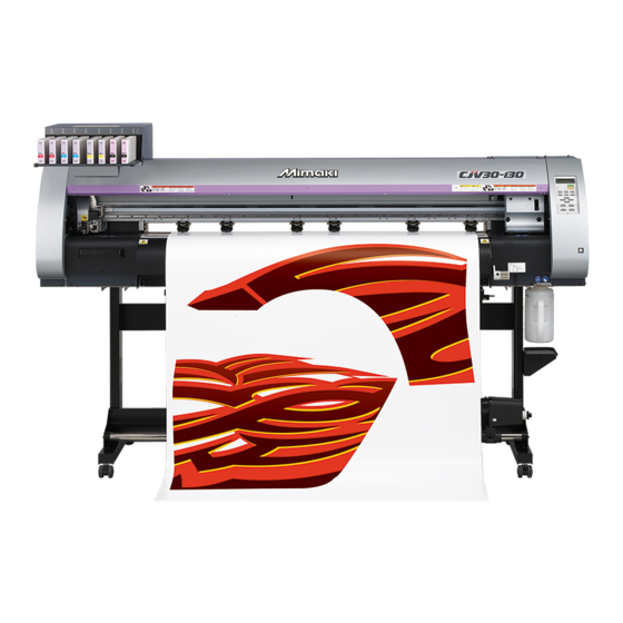
MIMAKI CJV30-100 Operation Manual
Printer cutter
Hide thumbs
Also See for CJV30-100:
- Maintenance manual (316 pages) ,
- Operating manual (274 pages) ,
- Product manual (30 pages)
Table of Contents
Advertisement
Quick Links
Advertisement
Table of Contents

Related Manuals for MIMAKI CJV30-100


Summary of Contents for MIMAKI CJV30-100
- Page 1 MIMAKI ENGINEERING CO., LTD. URL: http: // www.mimaki. co. jp/ D201873-14...
-
Page 2: Table Of Contents
Contents Caution ................vii Caution ................vii Requests ................vii FCC Statement (USA) ............vii Interference to televisions and radios ......vii Foreword ..............viii About This Operation manual ........viii Safety Precautions ............ix About Symbols ..............ix How to Read this Manual ..........xiv Chapter 1 Before Use Moving This Machine ..........1-2... - Page 3 Improving Cutting Quality ..........2-6 Operation Flow ............2-7 Turning the Power ON/OFF ........2-8 Turning the Power ON ..........2-8 Turning the Power OFF ..........2-9 Installing Tools ............2-10 When a Cutter Is Used ..........2-10 Exchanging Tool ............2-13 How to Attach a Ballpoint pen ........2-14 Setting a Medium ............
- Page 4 Chapter 3 Extended Functions – Printer – About User Types ............3-2 Registering All Printing Conditions Together (Type Registration) ............3-2 How to Register User Types ......... 3-2 Setting the Pinch Rollers ..........3-5 Recommended Setting for the Pinch Roller Pressure .. 3-5 Quantity of Pinch Rollers ..........
- Page 5 Chapter 4 Extended Functions – Cutting – Setting the Pinch Rollers ........... 4-2 Recommended Setting for the Pinch Roller Pressure and Number of Pinch Rollers ........4-2 Quantity of Pinch Rollers ..........4-2 Setting for the Pinch Rollers .........4-3 Cutting out Data with Register Marks ....... 4-5 Flow of Cutting Data with Register Marks .....4-5 Entering Register Mark Detection Mode .......4-5 Notes on Inputting Data with Register Marks ....4-6...
- Page 6 Chapter 5 Extended Functions – Common Settings – Common Settings ............5-2 Setting the Pinch Rollers ..........5-3 Setting a Cut Method ............ 5-4 Setting CONFIRM. FEED ..........5-5 Setting the Expand Function ........5-6 Setting Margins ............5-8 Setting the RECEIVED DATA ........5-9 Setting Time ...............
- Page 7 Setting Regular Operations ........6-27 Setting the Regular Wiping Operation during a Printing Operation ............6-28 Setting the Refreshing Interval in the Standby Mode .6-30 Setting the Interval between Each PUMP Tube Washing Operation in the Standby Mode ....6-31 Setting the Cleaning Interval in the Standby Mode ..6-32 Other Maintenance Functions .........
-
Page 8: Caution
Operation of this equipment in a residential area is likely to cause harmful interference in which case the user will be required to correct the interference at his own expense. In the case where MIMAKI-recommended cable is not used for connection of this device, limits provided by FCC rules can be exceeded. -
Page 9: Foreword
Foreword Thank you very much for your purchase of the MIMAKI Printer Cutter "CJV30-60/100/130/160". The CJV30-60/100/130/160 is a Printer Cutter for high-quality printing enabled by solvent ink (4 or 6 colors) with a cutting function installed on it. • 4-colors version : 2 each of Cyan, Magenta, Yellow and Black color ink cartridge are usable. -
Page 10: Safety Precautions
Safety Precautions About Symbols Symbols are used in this Operation manual for safe operation and for prevention of damage to the machine. One symbol is used for one caution. Please understand the meaning of each symbol and use this machine safely. Symbols and Their Meanings Meaning Failure to observe the instructions given with this symbol can result in death or serious injuries to... - Page 11 Check first that the machine no longer shocks. produces smoke, and then contact your distributor or a sales office of MIMAKI for repair. Never repair your machine by yourself since it is very dangerous for you to do so.
-
Page 12: Precautions For Use
MIMAKI. How to Handle Ink Caution about the Moving Parts • When cleaning the ink-station or the heads, make •... -
Page 13: Periodic Replacement Parts
• When any ink other than the CJV30 genuine ink is used, How to Handle Media the machine will not operate for its own protection. • Use media recommended by MIMAKI to ensure reliable, • Do not use the CJV30 genuine ink for other printers high-quality printing. - Page 14 Safety Precautions Cautions about Installation Caution A place where the temperature A place exposed to direct On an inclined surface or humidity sunlight changes significantly • Use the machine under the following environmental conditions: •Operating environment: 20 to 35°C 35 to 65% (Rh) A place exposed to direct air Around a place where fire is A place that vibrates...
-
Page 15: How To Read This Manual
How to Read this Manual... -
Page 17: Before Use
Chapter 1 Before Use This chapter describes the items required to understand before use, such as the name of each part of the machine or the installation procedures. Moving This Machine........1-2 Media ............1-11 Where to Install This Machine ..... 1-2 Usable Sizes of Media .......1-11 Working Environmental Temperature .. -
Page 18: Moving This Machine
1000 mm or more CJV30-60 : 2524 mm CJV30-100 : 2934 mm CJV30-130 : 3289 mm CJV30-160 : 3538 mm Working Environmental Temperature Use this machine in an environment of 20 to 35°C to ensure reliable printing. -
Page 19: Moving This Machine
Moving This Machine Moving This Machine Move this machine according to the following steps when this machine needs to be moved on the same step-free floor. • When the machine is moved to any place other than on the same step-free floor, contact your distributor or our service office. -
Page 20: Names Of Parts And Functions
Names of Parts and Functions Front Side of the Machine Maintenance cover Open the cover when carrying out maintenance. Even Ink cartridge when the power switch is OFF, keep the cover closed. The cartridge contains ink for each color. Cartridge protection cover This cover prevents an injury to the operator or the breakage of the machine caused by the protrusion of the 440-cc cartridge. -
Page 21: Rear/Sides
Names of Parts and Functions Rear/Sides Clamp lever (rear) Interlocks with the clamp lever in the front of this machine. Pre-heater Preheats the media before printing. (Located inside the platen) Cleaning solution cartridge Set a dedicated Washings cartridge (optional). Roll holders Holds a media by inserting it into the right and left ends of the core of the roll media. -
Page 22: Operation Panel
Operation Panel Display CONSTANT lamp Displays the status of the machine, set Lights up in green when the heater temperature reaches the set items and errors. temperature. HEAT lamp Lights up in orange during heating up of the heater. Use this key to switch the modes between print mode (PRINT MODE lamp is ON) and cut mode (CUT MODE lamp is ON). -
Page 23: Heater
Names of Parts and Functions Heater Pre-heater/Print heater/Post-heater are equipped on the platen. The Pre-heater is used for pre-heating of the media prior to printing to prevent rapid changes in temperature. The Print-heater improves the image quality in printing. The Post-heater dries ink after printing. •... -
Page 24: Carriage
Carriage The carriage consists of the printer unit and the cutter unit. Cutter unit Printer unit The cutter unit is used for The printer unit is used for cutting and printing with a printing. pen. Conjunct unit In concert with the data sent from a computer or the movement of the main body, switching is performed between printer unit and cutter unit. -
Page 25: Capping Station
Names of Parts and Functions Capping Station • Be sure to wear the attached goggles in cleaning within the capping station to protect your eyes against ink. The capping station consists of the ink caps, the wiper for cleaning the heads, etc. The ink caps prevent the nozzles in the ink heads from drying up. -
Page 26: Pen-Line Rubber
Names of Parts and Functions Pen-line Rubber Cutting and printing with a pen are performed on the pen line rubber. If you want to perform dotted line cutting, follow the steps below. Pen-line Rubber When performing dotted line cutting: Remove the pen-line rubber. (1) Insert a flathead screwdriver or equivalent tool into the gap between the left end of the pen-line rubber and the platen. -
Page 27: Media
Caution in Handling of Media Pay attention to the followings for handling of media. • Use media recommended by MIMAKI. Such media ensures reliable and high-quality printing. • Set the heater temperature to meet the characteristics of the media. -
Page 28: Connecting Cables
Connecting Cables Connecting USB2.0 Interface Cable Connect the PC and this machine with the USB2.0 interface cable. USB cable • Your application must be compatible with USB 2.0. • Contact a RIP maker near your location or our office when the USB2.0 interface is not attached to the PC. -
Page 29: Connecting The Power Cable
Connecting Cables Removing USB memory If a USB memory module is inserted in the personal computer to which a CJV30 machine is connected, click "Stop" in the "Safely Remove Hardware" window by following the instructions given there first and then remove the module. -
Page 30: Inserting Ink Cartridges
Inserting Ink Cartridges Insert ink cartridges. Shake the ink cartridge as shown on the right. Insert the ink cartridge. • Insert the ink cartridge lengthwise with the surface having IC chips pointing to the left side. • Colors are displayed on the display as follows. Black: K, Cyan: C, Magenta: M, Yellow: Y, Light cyan: c, Light magenta: m, White: W, Silver: S, Light black: k Changing an Ink Cartridge... -
Page 31: Caution In Handling Of Ink Cartridges
• Do not shake ink cartridges violently. This may result in ink leakage from the ink cartridges. • Never refill the ink cartridge with ink. A refilled ink cartridge can cause trouble. Remember that MIMAKI assumes no responsibility for any damage caused by the use of an ink cartridge refilled with ink. -
Page 32: Menu Mode
Menu Mode This machine has 4 modes. Each menu mode is described below. Not-ready This is the mode in which the medium has not been detected yet. • The keys other than the key are effective. LOCAL LOCAL is the mode for the preparation state. There are two LOCAL modes: [Printer mode] and [Cutting mode]. -
Page 33: Basic Operations
Chapter 2 Basic Operations This chapter describes procedures and setting methods for ink and media preparation, tool installation for cutting, and printing and cutting. User Type for Printing ........ 2-2 Test Printing ..........2-35 Settings That Can Be Registered in User Perform test printing with the normal test Types ............ -
Page 34: User Type For Printing
User Type for Printing Register a printing condition according to each of the media that you use in a user type beforehand. When you replace one medium with another, you can set the optimum printing condition only by changing one user type to another. -
Page 35: About Tool Conditions During Cutting
About Tool Conditions during Cutting Register a cutting condition according to each of the media that you use in a tool condition beforehand. When you replace one medium with another, you can set the optimum cutting condition only by changing a tool condition to another. -
Page 36: Registering A Tool Condition
Registering a Tool Condition Press the key in LOCAL to select the < L OCA L . > [ # 0 1 ] CU T 1 3 0 / 6 0 / 0 . 3 0 ) cutting mode. Press the key. - Page 37 About Tool Conditions during Cutting • When the printing-with-a-pen condition (PEN) has been selected in Step 3, SPEED: 30 cm/s and PRESSURE: 60 to 80g should be handled as reference values. • It is recommended to check whether the condition set by performing test cutting is proper after registering the tool condition.
-
Page 38: Improving Cutting Quality
About Tool Conditions during Cutting Improving Cutting Quality Cutting quality can be improved by reducing the level of acceleration speed for cutting. • If you set the speed reduction level, cutting speed will become slower. (Minimum operation acceleration speed: 0.1G) Press the key in LOCAL to select the cut- <... -
Page 39: Operation Flow
Operation Flow Print Print & Cut Turning the power ON Refer to P. 2-8 "Turning the Power ON/OFF". Installing tools Refer to P. 2-10 "Installing Tools". Setting media Refer to P. 2-15 "Setting a Medium". Selecting a user type Refer to P. 2-2 "User Type for Printing". -
Page 40: Turning The Power On/Off
Turning the Power ON/OFF Turning the Power ON This machine is provided with the following two power switches: Main power switch : It is located on the side of this machine. Keep this switch ON all the time. Power switch : Normally, use this switch to turn the power ON/OFF. -
Page 41: Turning The Power Off
Turning the Power ON/OFF Turning the Power OFF When having ended the operation of the machine, turn the power OFF by pressing the power switch located on the front side. Check the following items when turning the power OFF. • If the machine is receiving data from the PC or if there is any data that has not been output yet •... -
Page 42: Installing Tools
Installing Tools This machine allows you to use the following tools: Cutter : This tool is selected when an image printed on a medium is cut or when letters are cut with a cutting medium. Pen (water-based ballpoint pen) : This tool is used to perform “test printing” for checking how images or letters are cut actually. - Page 43 Installing Tools Adjusting the Blade Edge The blade edge needs to be adjusted according to the type of cutter and medium you use. After having adjusted the blade edge, set cutting conditions and conduct test cutting to check how the cutter cuts. •...
- Page 44 Installing the Cutter Holder • Insert the cutter holder firmly so that there is no space under the holder. Brim Insert the cutter holder into the tool holder. • Press the cutter brim on the tool holder. Fix the cutter holder. •...
-
Page 45: Exchanging Tool
Installing Tools Exchanging Tool Press the key in LOCAL to select cutting < L OCA L . > [ # 0 1 ] CU T 1 3 0 / 6 0 / 0 . 3 0 ) mode. Press the key. -
Page 46: How To Attach A Ballpoint Pen
Installing Tools How to Attach a Ballpoint pen • When you use a ballpoint pen sold on the market, use one with a diameter of 8 to 9 mm. Image quality may change, depending on the pens to be used. (Recommended ballpoint pen: K105-A and K105-GA (product No.) manufactured by Pentel Co., Ltd.) •... -
Page 47: Setting A Medium
Setting a Medium This machine can be used with a roll medium and leaf medium. For usable media, refer to P.1-11 "Usable Sizes of Media". Adjusting the Head Height Adjust the head height according to the thickness of the medium you use. •... - Page 48 Return the carriage to the station position. For the Adjusting Lever and the Range Height-adjusting lever Head height Switching area 2 mm Thin (The set position before shipping) Switch by user Thick 3 mm • Set the lever to "Thick" when a thicker medium such as tarpaulin or FF is used. •...
-
Page 49: Adjusting The Position Of The Pinch Roller According To The State Of A Medium
Setting a Medium Adjusting the Position of the Pinch Roller According to the State of a Medium Adjust the position of the pinch roller according to the width of the medium to be set. This machine feeds the medium with a pinch roller and grid roller for printing or cutting. The pinch roller should be above the grid roller. - Page 50 Medium Size and the Grid Roller (CJV30-160) The grid roller positions are determined by the size of the medium. • To feed the medium smoothly, select the grid roller positions so that the medium can be held at equally spaced intervals. •...
- Page 51 Setting a Medium Medium Size and the Grid Roller (CJV30-130) The grid roller positions are determined by the size of the medium. • To feed the medium smoothly, select the grid roller positions so that the medium can be held at equally spaced intervals.
- Page 52 Medium Size and the Grid Roller (CJV30-100) The grid roller positions are determined by the size of the medium. • To feed the medium smoothly, select the grid roller positions so that the medium can be held at equally spaced intervals.
- Page 53 Setting a Medium Medium Size and the Grid Roller (CJV30-60) The grid roller positions are determined by the size of the medium. • To feed the medium smoothly, select the grid roller positions so that the medium can be held at equally spaced intervals.
-
Page 54: Roll Stopper
Roll Stopper When the medium is set and a certain amount is pulled out, the roll stopper function is activated to stop the roll holder temporarily. This function is provided to prevent unnecessary pull-out of the medium. • The roll stopper works with the clamp lever. Do not push the clamp lever down while the roll stopper is caught between the roll stopper arm and the this machine. -
Page 55: Maximum Print Area/Cut Area
( P.2-33). The white area shown in the following figure represents the maximum print/ cut area. The area other than that is the dead space that cannot be printed/cut. CJV30-60 CJV30-100 CJV30-130 CJV30-160 Maximum printing/cut width 610 mm... -
Page 56: Notes When Using Medium Holder
Notes When Using Medium Holder Setting Position of the Medium Set the medium so that the right end of the medium will be inside the area shown below. Set the medium so that the right end of the medium will be inside the area shown by an arrow. -
Page 57: Setting A Roll Medium
Setting a Medium Setting a Roll Medium Set a roll medium to the roll media hanger located on the back of this machine. • Take care not to drop the medium on your foot when setting the medium. It may cause an injury due to the medium. - Page 58 Tighten the roll holder fixing screw. • Check the Steps 2 to 3 again. Set the left end of the core of the roll medium on the left roll holder. • Push the roll medium onto the roll holder until the roll core is all the way seated.
- Page 59 Setting a Medium Pull out the roll medium out. (1) Raise the clamp lever from the front of this machine. (2) Pull out the roll medium gently and then stop pulling when locked lightly. Make the roll medium even, then lower the clamp lever.
- Page 60 Current mode and pinch roller pressure is Press the key. indicated with [>]. > PR I N T [ MMMMMMM ] CU T [ H _ _ _ _ _ H ] Check the current pinch roller pressure. • To change the set pinch roller pressure temporarily, follow the steps below. (1) Press to select a pinch roller to set.
-
Page 61: Take-Up Device
Setting a Medium Entering the Medium Remaining Amount When "Remaining amount of a medium to display" of the maintenance function is "ON" ( P.6-34) , the screen for entering medium remaining amount is displayed after detecting the medium width. • The medium remaining amount can be entered only when a medium or a roll is detected in the printer mode. -
Page 62: Setting The Torque Limiter
Setting the Torque Limiter The take-up device is provided with a torque limiter. The take-up torque can be adjusted with the torque limiter. (The torque limiter is set at the maximum value when shipped from the factory.) In the following cases, make the adjustment: (1) when the tension is too strong in using thin medium (2) when performing combined operation of print &... -
Page 63: Setting A Leaf Medium
Setting a Medium Setting a Leaf Medium Unlike a roll medium, a leaf medium does not need to be retained with the roll holders. • If the cutter unit is on the platen, press the key to evacuate the cutter unit. ( P.2-49) Raise the clamp lever. - Page 64 Press to set the number of the pinch roller at * * P I NCH RO L L ER * * P I NCH ROL L ER : N o . t o 1 the left end of the medium. •...
-
Page 65: When Changing The Origin
Setting a Medium When Changing the Origin The position of the print origin can be changed. Move the print origin to the intended position and determine the origin position. • When changing the origin position in the printer unit, use the [ORIGIN] seal put on the printer unit as a reference. - Page 66 Setting a Medium Reference for Setting Position of the Origin The print origin in the depth direction (X') is positioned at about 40 mm rearward from the cutting line. The scanning direction (Y’) is positioned at the left end of the first pinch roller (the right end pinch roller seen from the front of the main body).
-
Page 67: Test Printing
Test Printing Print a test pattern to check that there are no discharging defects such as nozzle clogging (slight touching of ink or nozzle missing). About test patterns This machine provides you two test patterns. Normal test pattern (when using ink other than white ink) When you use ink that you can check by printing a test pattern on a white media, print this test pattern. -
Page 68: Perform Test Printing With The Normal Test Pattern
Perform test printing with the normal test pattern • If a medium has been set P.2-15 • If the origin position has been set Check before test printing. • If the head gap has been adjusted P.2-15 Press the key in LOCAL to select the <... -
Page 69: Perform Test Printing With The Test Pattern For Checking White Ink
Test Printing Perform test printing with the test pattern for checking white ink • If a medium has been set P.2-15 • If the origin position has been set Check before test printing. • If the head gap has been adjusted P.2-15 Press the key in LOCAL to select the... -
Page 70: Check Warning Of White Nozzle Status (Only When Using Ss21 White Ink)
Test Printing Check warning of white nozzle status (Only when using SS21 white ink) As SS21 white ink is easier to cause nozzle clogging compared to other ink, you must keep the nozzle status normal even when you do not discharge it. In order to keep the nozzle status normal, this machine displays the warning C h e c k t h e... -
Page 71: Head Cleaning
Head Cleaning About head cleaning There are two types of head cleaning. Depending on the test printing result, perform to solve nozzle clogging. Check the printed test pattern result and perform cleaning depending on the status. Select one from the three types below: NORMAL : When any line is missing SOFT : When only head wiping is needed (when lines are bent) -
Page 72: Perform Spot Color Maintenance
Perform spot color maintenance Perform this to solve color heterogeneity due to settling down of pigment when using silver ink or white ink of ES3 ink. Spot color maintenance is selectable only when silver ink or white ink of ES3 ink has been filled for the firmware Ver.2.40 and later. - Page 73 Head Cleaning Slowly shake the removed ink cartridge more than twenty times right and left. • To prevent ink from leaking when you shake the cartridge, wear gloves and firmly cover the A part of the upper surface of the cartridge and the B part of the bottom surface of the cartridge with paper towels. Then, shake it more than twenty times right and left so that ink flows inside the cartridge.
- Page 74 Head Cleaning Remove the ink cartridge of the displayed color on the screen. • The lamp located above the cartridge lights to inform you of the ink cartridge to be removed. • After the ink cartridge is removed, ink discharging starts. * D I SCHARGE * 0 3 : 0 0 •...
-
Page 75: Test Cutting
Test Cutting Test cutting is performed to check whether the settings for tool conditions are appropriate. In test cutting, two squares shown right are cut. • When the cutter cuts badly because of the wear of the blade, the value of PRESSURE can be increased temporarily to deal with the problem. -
Page 76: Preparing For The Heaters
Preparing for the Heaters Changing the Temperature Settings for the Heaters The temperature settings for the heaters can be changed and stored in P.3-12 "Changing the Temperature Settings for the Heaters". Described here is how to change the already set temperature. Set the heater temperature according to the characteristics of the media you use. -
Page 77: Checking The Heater Temperature
Preparing for the Heaters Reference for Temperature Setting Ink type ES3 ink SS21 ink Glossy Media type Tarpaulin All media chloroethylene Pre-heater setting 40°C 40°C 40°C 35°C Print heater setting 40°C 40°C 40°C 35°C Post-heater setting 50°C 50°C 50°C 50°C •... -
Page 78: Printing Data
Printing Data Starting a Printing Operation • When using a roll medium, rewind the medium by hand before printing so that it is not loose. When the roll medium has not been rewound tightly, it may cause the image quality to deteriorate. •... -
Page 79: Stopping A Printing Operation
Printing Data Stopping a Printing Operation Perform the following operation when stopping a printing operation halfway. Press the key during printing. < L OCA L . 1 > [ # 0 1 ] WI D TH : * * * * mm •... -
Page 80: Data Cutting
Data Cutting Starting a Cutting Operation Also when printing data with a pen, follow the procedure below. When the machine is in a REMOTE state, the PC transmits data to be cut. • The pressure is switched automatically in concert with the pinch * REMOT E . -
Page 81: Stopping A Cutting Operation (Data Clear)
Data Cutting Stopping a Cutting Operation (Data Clear) If you want to stop a cutting operation of the received data, clear the data. • When clearing the data, the process will not restart even if you press the key. • After clearing the data, switching to the remote mode and receiving another data, new data will be cut. Press the key in LOCAL. -
Page 82: Cutting A Medium
Cutting a Medium There are two methods of cutting medium: automatic and manual. • When cutting a medium, select a cutting method according to the size of the medium. ( P.5-4 "Setting a Cut Method") • When a medium is cut, be careful that the printed side does not touch the floor or the printed side of other already cut media. - Page 83 Chapter 3 Extended Functions – Printer – This chapter describes the operation procedures for using the printing function more conveniently and each setting procedure. About User Types ........3-2 Setting Priority Order........ 3-22 Registering All Printing Conditions Together Setting Automatic Cleaning ..... 3-24 (Type Registration) ........
-
Page 84: About User Types
About User Types Registering All Printing Conditions Together (Type Registration) This machine allows you to register printing conditions in each of the user types (1 to 4). Register a printing condition according to each media that you use in a user type beforehand. When you replace one medium to another, you can set the optimum printing condition only by changing one user type to another. - Page 85 About User Types List of Functions to Be Set in User Types This section describes the overview of each function to be set and set values that can be registered in user types. The underlined has been set as default. Function Name Set Value Overview...
- Page 86 About User Types Function Name Set Value Overview PRIORITY ( P.3-22) INDIVIDUALLY / ALL HOST / Used to set the priority order of settings (by ALL PANEL host/panel). Used to set the following items individually when the individual setting is selected. •...
-
Page 87: Setting The Pinch Rollers
Quantity of Pinch Rollers The following table shows the quantity of the pinch rollers for each model. Check the pinch rollers on your machine for quantity. Model Quantity CJV30-160 7 pieces CJV30-130 6 pieces CJV30-100 4 pieces CJV30-60 3 pieces... -
Page 88: Setting For The Pinch Rollers
Setting for the Pinch Rollers This section describes the setting procedure for CJV30-160. For CJV30-130/100/60, the number of pinch rollers set in Step 10 varies. Pinch Roller No. Pinch Roller Middle pinch rollers End pinch roller End pinch roller (left end) (right end) •... - Page 89 Setting the Pinch Rollers Press to set the pressure for the middle ENDS : M I D . [ H _ _ _ _ _ H ] I NNER : I D . N o . 7 - 1 pinch rollers. •...
-
Page 90: Setting Media Correction
Setting Media Correction In the following cases, be sure to set medium correction and correct the amount of the medium feeding. • when replacing the kind of the medium ( P.2-15) • when changing the heater temperature ( P.2-44) • when changing the pinch roller pressure in the pinch roller setting ( P.3-6) If the correction value is not appropriate, stripes may appear on the printed image, thus resulting in a poor printing. - Page 91 Setting Media Correction Press to select [MEDIA COMP.]. [ 1 ] MED I A COMP . < e n t > Press the key. [ 1 ] MED I A COMP . PR I N T S T AR T Press the key to print a correction pattern.
-
Page 92: If The Positions Of Dots Shift
If the Positions of Dots Shift... When the condition for printing (medium thickness/head height/setting of pinch roller pressure/ink type/etc.) has been changed, perform the following operation to correct the ink drop position for bidirectional (Bi) printing and obtain the proper printing result. •... - Page 93 If the Positions of Dots Shift... Displays the current Press to correct the dot position of Pattern 1. head height. (H)... High (thick) • Correction value: -40 to 40 (L) ... Low (thin) • Check the test patterns. The position where an outward feeding line and a return feeding line become one straight line is the correction value.
-
Page 94: Changing The Set Values Of The Heaters
Changing the Set Values of the Heaters Reference for Temperature Setting Ink type ES3 ink SS21 ink Media type Glossy chloroethylene Tarpaulin All media Pre-heater setting 40°C 40°C 40°C 35°C Print heater setting 40°C 40°C 40°C 35°C Post-heater setting 50°C 50°C 50°C 50°C... - Page 95 Changing the Set Values of the Heaters Press to select [HEATER]. [ 1 ] HE A T ER < e n t > Press the key twice. PR T POS T 5 ° C 5 ° C 5 ° C •...
-
Page 96: Adjustment To An Appropriate Temperature
Adjustment to an Appropriate Temperature This section describes how to adjust the temperature of the heaters to an appropriate one. Because the heater temperature should be different, depending on the types of media, ambient temperature, etc., set an appropriate temperature for each medium. For non-coated media or media on which ink is slow to dry, increase the heater temperature so that the ink fixing and drying characteristics can be improved. -
Page 97: When The Heater Temperature Does Not Reach The Preset One
Changing the Set Values of the Heaters When the Heater Temperature Does Not Reach the Preset One When the heater temperature is too low or the ink capacity (ink limit) is too small, printing failures, such as beading and banding, may occur. Beading is a phenomenon that adjacent dots attract and stick to one another. -
Page 98: Setting The Printing Method
Setting the Printing Method In the printing method setting, the following items are set: • Printing quality (DRAFT) : Printing quality in the DRAFT mode (resolution in the scanning direction: 540 dpi) is set. • Printing quality (FINE) : Printing quality in the FINE mode (resolution in the scanning direction: 720 dpi) is set. •... - Page 99 Setting the Printing Method When changing the details of printing quality in each [ 1 ] DRA F T QUA L I T Y resolution, press to select a resolution. 5 4 0 x 7 2 0 < e n t > (1) Press to select a resolution.
-
Page 100: Setting A Scanning Direction
Setting a Scanning Direction Set Value Overview Printing is performed in both outward and return directions of the printer unit. Bi-D Select this when you want to print in a shorter period of time. Printing is performed only in the outward direction of the printer unit. Uni-D Select this when you want to print finer. -
Page 101: Setting Logical Seek
Setting the Printing Method Setting Logical Seek Set Value Overview The printer unit moves according to the size of the data during printing. Select this when you want to print in a shorter period of time. The printer unit moves from the right edge to the left edge of a medium, regardless of the size of the data. -
Page 102: Setting For White-Laying Printing
Setting the Printing Method Setting for White-laying Printing When using SS21W-2 (SPC-0504W-2) white ink, you can print with other colors after printing with white ink. This section describes the method of printing with white ink and other color inks. Set Value Overview White ink and other color inks are printed at the same time. -
Page 103: Setting Drying Time
Setting Drying Time The following items for ink drying time are set. Set Item Set Value Overview Ink drying time for each scanning is set. SCAN 0.0 to 19.9 sec (During bidirectional printing, the machine stops for a certain period of time specified for each of the outward and return scanning.) Ink drying time after printing has been complete is set. -
Page 104: Setting Priority Order
Setting Priority Order It is determined which is prioritized for printing, the setting by the machine (panel) or the setting by the PC (host). Set Value Overview It is determined which is prioritized for the items below this table, the setting by this machine INDIVIDUALLY (panel) or the setting by the PC (host). - Page 105 Setting Priority Order Perform the same operations as in Steps 9 and 10 to set other items. Press the key several times to end the setting. • Even with the setting by the host being prioritized, the items set by the panel become effective if they have not been specified by the host.
-
Page 106: Setting Automatic Cleaning
Setting Automatic Cleaning You can set items so that the head cleaning is automatically performed when printing has been completed for the set length. When printing has been completed, the machine measures the length of a medium printed after the previous head cleaning and performs the cleaning automatically if necessary. - Page 107 Setting Automatic Cleaning Press the key. I N T ERVA L : T Y PE 0 0 0 mm : NORMA L TYPE :NORMAL Press to set a cleaning interval and SOFT INTERVAL: a cleaning type. HARD 10 to 10,000 mm Item selection : Select one with Setting of an interval and type : I N T ERVA L...
-
Page 108: Setting Cleaning During Printing
Setting Cleaning during Printing It is set whether head cleaning is performed automatically during printing. In cleaning during printing, a cleaning interval is set according to the length of a printed medium. Printing is interrupted each time a medium is printed for the set length, and head cleaning is performed automatically during the interval. -
Page 109: Other Settings
Other Settings Change the settings according to the types of use. Press the key in LOCAL to select the < L OCA L . 1 > [ # 0 1 ] WI D TH : * * * * mm printing mode. -
Page 110: Other Settings
Other Settings List of Settings The underlined has been set as default. Function Name Overview Set Value Setting the pinch roller pressure and the pinch PINCH ROLLER roller numbers according to the medium to be See P.3-5. used. MEDIA COMP. A medium-feeding rate is corrected. -
Page 111: Copying The Set Contents
Copying the Set Contents The contents you set can be copied to other type. Press the key in LOCAL to select the < L OCA L . 1 > [ # 0 1 ] WI D TH : * * * * mm printing mode. -
Page 112: Initializing The Settings
Initializing the Settings The already configured settings are initialized. (Resetting) The setting items of the selected type are reset. Press the key in LOCAL to select the < L OCA L . 1 > [ # 0 1 ] WI D TH : * * * * mm printing mode. -
Page 113: Machine Settings
Machine Settings Common settings are functions for using this machine easily. The following items can be set in Machine settings. Item Overview Set Value OFF / STOP The time until the rotation of the exhaust fan stops after printing has been 10 to 120 to 240 min/ DEODRIZE TIME... -
Page 114: Setting The Dryness Feed
Press the key. Press to select a set value. STOP TIME : 0 to 240 sec or continuous operation RENEW : When you operate the exhaust fan, select "ON". When you stop the fan, select "OFF". Press the key. • Press the key several times to end the setting. -
Page 115: Stamp Setting
Machine Settings Stamp Setting It is set whether information, such as printing conditions and a printing date, is output after printing has been completed. Press the key in LOCAL to select the < L OCA L . 1 > [ # 0 1 ] WI D TH : * * * * mm printing mode. -
Page 116: Setting The Test Print Arrange
Setting the Test Print Arrange The orientation of test patterns that are printed when test printing is repeated can be set. : When the set value is "FEED DIR." : When the set value is "SCAN DIR." Media-feeding direction Press the key in LOCAL to select the <... -
Page 117: Change The Operation Condition Of The Room Temperature
Machine Settings Change the operation condition of the room temperature If you print in the status that the temperature of the place in which the machine has installed (room temperature) is out of the usable temperature range, ink discharging defect or changing color may occur, and it adversely affects the printing quality. -
Page 118: Extension Of Ink Expiry Month
Extension of Ink Expiry Month Ink expiry month can be extended for six months from the expired month. When used without extension, ink becomes unusable after two months of the expiry month. Extension of Ink Expiry Month The following setting or confirmation screen appears when the power of this machine is turned on, or when expired ink cartridge is set. -
Page 119: When An Ink Expiry Month Is Extended
Extension of Ink Expiry Month When an ink expiry month is extended Example: If expiry month of your ink cartridge is February 2014. • When the expiry month is not extended February March April May or later Not printable Printable continuously Not printable (Unusable) continuously A message "Expiration:2MONTH"... -
Page 120: Switch Setting Of Ink Supply Path
Switch Setting of Ink Supply Path For the ink supply, condition of the ink cartridge to be used first by the double-cartridge automatic switching function can be selected. This setting is only available for 4-color set. • When expired ink cartridge is set, the expired cartridge is used first regardless of the setting below. •... -
Page 121: Printing Mode
Switch Setting of Ink Supply Path When both ink cartridge and MBIS are used When both an ink cartridge and the optional bulk ink system (MBIS) are set in the supply paths of the same color for 4-color ink set, you can select the ink to be used first. •... - Page 122 3-40...
- Page 123 Chapter 4 Extended Functions – Cutting – This chapter describes the operation procedures for using the cutting function more conveniently and each setting procedure. Setting the Pinch Rollers ......4-2 Changing the Order of Cutting ....4-28 Recommended Setting for the Pinch Roller Setting the SORTING ........4-29 Pressure and Number of Pinch Rollers ..
-
Page 124: Setting The Pinch Rollers
• Adjust the pinch roller pressure according to the situation. Quantity of Pinch Rollers The following table shows the quantity of pinch rollers for each model. Check the pinch rollers on your machine for quantity. Model Quantity CJV30-160 7 pieces CJV30-130 6 pieces CJV30-100 4 pieces CJV30-60 3 pieces... -
Page 125: Setting For The Pinch Rollers
Setting the Pinch Rollers Setting for the Pinch Rollers This section describes the setting procedure for CJV30-160. For CJV30-130/100/60, the number of pinch rollers set in Step 10 varies. Pinch Roller No. Pinch Roller End pinch roller Middle pinch rollers End pinch roller (left end) (right end) - Page 126 Setting the Pinch Rollers Press to set the pressure for the middle ENDS : M I D . [ H _ _ _ _ _ H ] I NNER : I D . N o . 7 - 1 pinch rollers. •...
-
Page 127: Cutting Out Data With Register Marks
Cutting out Data with Register Marks If you create register marks on an output image, the cutter unit detects these marks and cuts the image out automatically following these marks. This helps you to make stickers, etc. This section describes how to cut the printed medium. Refer to P.4-10 for the combined operation of print &... -
Page 128: Notes On Inputting Data With Register Marks
Notes on Inputting Data with Register Marks There are some limitations on preparing data with register marks. In order to make full use of this function, read the following instructions carefully and prepare data with register marks properly. • The register mark described here is intended to detect the medium skew and the lengths along the X and Y axis. - Page 129 Cutting out Data with Register Marks No-printing Area around the Register Marks An area around a register mark (from the mark origin to the mark size area) is a non-printing area. There must be no data printed or stain in this area. Otherwise, a wrong origin may be detected or a mark read error can occur.
- Page 130 The Size of a Register Mark Suited for the Distance between the Marks The size (B) of a register mark suited for the distance (A) between the marks is as shown below. If the mark size (B) is too small relative to the distance (A), the marks may not be detected correctly. Be sure to prepare the register marks with an appropriate size.
- Page 131 Cutting out Data with Register Marks The Recommended Size of the Area Defined with a Set of Four Register Marks It is recommended that the size of the area defined with a set of four register marks is in the range of A4 size (210 mm x 297 mm) to A3 size (297 mm x 420 mm).
- Page 132 Notes on Register Mark Detection Observe the following precautions on register mark detection. • When you retry medium detection, medium skew correction, scale correction between register marks, and the position of the origin are cleared. • Once the cutter unit detects marks, it will set the origin at the location of TP1. If you change the position of the origin to a different location using the jog keys, the origin at the new location will supersede the origin at TP1.
-
Page 133: Setting Register Mark Detection
Cutting out Data with Register Marks Setting Register Mark Detection When you want to cut the data with register marks, set the following without fail. Press the key in LOCAL to select cutting < L OCA L . > [ # 0 1 ] CU T 1 3 0 / 6 0 /... - Page 134 Set Items MARK DETECT The higher the number of detected points, the higher the cutting accuracy. Select "1pt" when using Raster Link Pro4 SG (or later) or FineCut. Set Value Description Select this setting for cutting a normal medium, not for cutting the outline. Detects the TP1.
- Page 135 Cutting out Data with Register Marks MARK TYPE Set Value Description Select either one of the following types of register marks. TYPE1 TYPE2 MARK : TYPE 1 MARK : TYPE 2 COPIES (X) / COPIES (Y) Set Value Description 1 to 9999 Effective when the same pattern is multi-printed at regular intervals.
- Page 136 Setting of skew check Set Value Description 0 to 99 mm This will set the allowable value of sheet declination when copying continuously. When copying continuously for roll sheet, the printing position may be misaligned gradually because of the sheet declination etc. In such a case, the operation can be continued by detecting register marks again with the following procedures: If the coordinate value of B axis of the Register mark 1 is misaligned exceeding the setting value, cutting operation suspends.
-
Page 137: Method Of Detecting Register Marks
Cutting out Data with Register Marks Method of Detecting Register Marks • If the medium is curled, straighten it. When using a cutting software having no mark function, use a medium which has neither stains nor images in the area (A) located between TP1 and TP2 and in the area (B) located between TP1 and TP3. - Page 138 Press the key after completing the settings. • The plotter will start detecting the register marks according to the settings of [MARK DETECT]. • See "MARK DETECT" ( P.4-12) for the number of register marks. • In case the cutter unit cannot detect any register marks, it displays "ERROR36 MARK DETECT" on the display.
-
Page 139: When Cutting Failed
Cutting out Data with Register Marks When Cutting Failed Checking the Sensor for the Register Mark Detection • You cannot check the response correctly by moving the head or medium manually. Be sure to follow the steps below to check the response. •... - Page 140 Press the key. MARK SENSOR S I Z E = 1 0 mm Press to set the size of the register mark, and MARK SENSOR FORM : T YP E 1 then press the key. • Set value: 4 to 40 mm •...
- Page 141 Cutting out Data with Register Marks Detect Operation Scan in the X direction (plus direction) to confirm that the line can be detected. • The buzzer sounds when the line is detected. If the line is not detected, the buzzer does not sound. Scan in the X direction (minus direction) to confirm that the line can be detected.
- Page 142 Correcting the Light Pointer Position If the cutter unit fails to recognize any register mark properly, the possible cause is an error in the positional relationship between the mark sensor and the light pointer. In this case, correct the position of the light pointer. Install a water-based ballpoint pen in the tool holder.
- Page 143 Cutting out Data with Register Marks Adjust the Sensitivity (Light Intensity) of the Mark Sensor LED (Automatically) If an error occurs frequently in register mark detection, a possible cause is an improper sensitivity of the mark sensor LED. In this case, adjust the sensitivity (light intensity) of the mark sensor LED. •...
-
Page 144: Setting Automatic Cutting
Setting Automatic Cutting A medium is automatically cut off after cutting has been complete. Press the key in LOCAL to select the < L OCA L . > [ # 0 1 ] CU T 1 3 0 / 6 0 / 0 . -
Page 145: Dividing And Cutting
Dividing and Cutting When the function of dividing and cutting has been set, data that is The part that has jutted larger than the width of a medium can be divided and cut. (Dividing out from a medium is and cutting function) divided and cut. - Page 146 Press to select [FRAME CUT] [ CU T 1 ] D I V I S I ON CU T F RAME CU T : OF F and press the key. • When you want to cut a frame, select "ON". Press to select [MARK CUT] [ CU T 1 ] D I V I S I ON CU T...
-
Page 147: Cutting Data By Using The Dividing And Cutting Function
Dividing and Cutting Cutting Data by Using the Dividing and Cutting Function Data is received from the computer. Effective area • When data has jutted out from the cut area, a screen shown right appears. Origin * REMOT E . <... -
Page 148: Cutting With A Dotted Line
Cutting with a Dotted Line Data to be cut is not cut out completely but is cut with a dotted line. Cutter To perform cutting with a dotted line, you must set the tool condition to “HALF”. Medium Not cut out but left Cut out as it is (half cut) •... - Page 149 Cutting with a Dotted Line Press to select the length of [ CU T 1 ] HA L F CU T CU T L ENGTH 5 0 mm the part cut out from the medium. • Set value: 5 to 150mm Press the key.
-
Page 150: Changing The Order Of Cutting
Changing the Order of Cutting By changing the order of pieces of data for cutting transmitted from the host computer, you can change the order of cutting them. (Sorting function) When data to be cut with a single stroke cannot be cut with a single stroke because of the order of pieces of data transmitted from a software application, you can cut the data with a single stroke by changing the order of cutting them. -
Page 151: Setting The Sorting
Changing the Order of Cutting Setting the SORTING Press the key in LOCAL to select the < L OCA L . > [ # 0 1 ] CU T 1 3 0 / 6 0 / 0 . 3 0 ) cutting mode. - Page 152 Press to select a set value of [AREA]. [ CU T 1 ] SOR T I NG AREA : 5 0 0 • Set value: OFF or 10 to 5,100 cm (by units of 10 cm) Press the key. Press the key several times to return to LOCAL.
-
Page 153: Procedure For Sorting
Changing the Order of Cutting Procedure for SORTING Transmit data. * REMOT E . < 1 0 0 KB > * * SOR T I NG * * • The size of the data that has not been processed yet in the reception buffer is displayed. Cutting (plotting with a pen) is not performed. -
Page 154: Cutting Out Data Without Register Marks
Cutting out Data without Register Marks To print & cut the data without register marks, adjust the misalignment between a printed image and the cutting line (P/C Adjust). • Before adjusting, set a PVC medium and attach the provided eccentric cutter for cutting. •... - Page 155 Cutting out Data without Register Marks Press the key. S E TUP S E L EC T : CU T 1 Press to select one from the tool conditions (CUT1 to CUT3, PEN, and HALF) and press the key. Press to select [P/C ADJUST] .
-
Page 156: Setting The P/C Scale Adjust
Press the key several times to return to LOCAL. • Even if you adjust with the P/C origin offset, misalignment may occur when you print & cut data actually in some cases. In such a case, you can adjust again by the procedures below: (1) Press the key to select the cutting mode. - Page 157 Cutting out Data without Register Marks Press the key. [ CU T 1 ] P / C AD J US T P / C OR I G I N OF S . < e n t > Press to select [P/C SCALE ADJ.] . [ CU T 1 ] P / C AD J US T P / C SCA L E AD J .
-
Page 158: Other Settings
Other Settings Change the settings according to the types of use. Press the key in LOCAL to select the < L OCA L . > [ # 0 1 ] CU T 1 3 0 / 6 0 / 0 . 3 0 ) cutting mode. -
Page 159: List Of Settings
Other Settings List of Settings The setting is as follows when purchasing: Function Name Overview Set Value Setting the pinch roller pressure and the pinch PINCH ROLLER roller numbers according to the medium to be See P.4-2. used. MARK DETECT See P.4-5. - Page 160 About the Cutting Mode Select "FINE" in any of the following cases: • When characters of which the size is 10 mm or less are cut. • When pictures or characters that have many sharp corners are cut. • When minute cutting is required. However, the edges of a finished pattern may become jagged when the data transmitted from the host computer is too complicated.
- Page 161 Other Settings About Over Cutting Specify whether the over cutting function is enable or unable and the Over cut : OFF length of the over cutting. If the length of the over cutting is set, cutting is performed with extra cutting space at the front by the specified amount of length at the start of cutting and tool up is performed at the end going too far.
-
Page 162: Copying The Setting Contents
Copying the Setting Contents The setting contents can be copied to other tool conditions. Press the key in LOCAL to select the < L OCA L . > [ # 0 1 ] CU T 1 3 0 / 6 0 / 0 . -
Page 163: Initializing The Settings
Initializing the Settings Press the key in LOCAL to select the < L OCA L . > [ # 0 1 ] CU T 1 3 0 / 6 0 / 0 . 3 0 ) cutting mode. Press the key. -
Page 164: Cutting Samples
Cutting Samples In such a case as when data cannot be cut normally, a sample stored in Sample of "Cut" this machine is cut to check the cause of the abnormality. Sample of "Logo" • When sample cutting has been performed, data stored in the reception buffer is deleted. •... - Page 165 Cutting Samples Press the key. S AMP L E CU T CU T S T AR T : e n t Press the key to start cutting. About the Result of Sample Cutting When sample data can be cut normally, but other data cannot be cut normally ...
-
Page 166: Cutting A Medium Into Multiple Pieces With A Certain Length
Cutting a Medium into Multiple Pieces with a Certain Length You can cut a medium into multiple pieces with a specified length. (Automatic media-cutting function) Settings Set Value Overview Cutting interval 10 to 10,000 mm Distance between the leading and terminal ends of a cut medium is set. Leading end 0 to 500 mm The length of a medium's leading end to be cut is set before automatic media... - Page 167 Cutting a Medium into Multiple Pieces with a Certain Length Press the key. • Cut is performed for the specified number of times. • Pressing the key suspends the operation. Press the key several times to return to LOCAL. 4-45...
-
Page 168: Perform Multiple Cuttings
Perform Multiple Cuttings Already received data can be copied (plotted with a pen) to produce a multiple number of pieces of data. (Up to 999 pieces) Origin position before data is copied to produce a multiple number of pieces of data (manual setting) Copying interval Origin position after data has been copied to produce a multiple number of pieces of data (automatic setting) - Page 169 Perform Multiple Cuttings • When copying data to produce a multiple number of pieces of data, make sure to set an origin again. When, immediately after data is copied to produce a multiple number of pieces, a piece of data is cut according to a specified number without setting an origin, data is cut (plotted with a pen) with themselves being overlapped.
-
Page 170: Setting The Step Size
Setting the Step Size For some application software (especially old ones), data output may possible only by different unit from the limit of resolution. In such a case, change this setting value and make the cutting performed in correct size. <... -
Page 171: Other Convenient Functions
Other Convenient Functions Medium Feeding Before you start cutting or printing with a pen, feed a certain length of the medium to allow a margin. By feeding the sheet beforehand, you can check for a skew of the medium or prevent a skew while cutting the long data (or printing the long data with a pen). -
Page 172: How To Turn The Heater Off In The Cutting Mode
Other Convenient Functions How to turn the heater OFF in the cutting mode Press the key in the cutting mode to turn the heater OFF. Press the key twice in the cutting HE A T ER P o w e r - o f f <... - Page 173 Chapter 5 Extended Functions – Common Settings – This chapter describes the operation procedures for using both the printing and cutting function more conveniently and each setting procedure. Common Settings................5-2 Setting the Pinch Rollers ..............5-3 Setting a Cut Method ...............5-4 Setting CONFIRM.
-
Page 174: Common Settings
Common Settings Common settings are functions for using this machine easily. The items set here are common to both the printing and cutting modes. The common settings are as follows: Item Meaning Set Value PR SETUP PWR ON ONLY/ Sets the setting of a pinch roller when detecting the medium. P.5-3 PR No.ONLY/ OFF CUT METHOD... -
Page 175: Setting The Pinch Rollers
Common Settings Setting the Pinch Rollers This is the setting methods of a pinch roller when detecting the medium. Set Value Overview The pinch roller number and the pinch roller pressure need to be set each time the medium is set, according to the width of the medium. -
Page 176: Setting A Cut Method
Setting a Cut Method Set the cutting method to cut the medium. Set Value Overview 2 STEP The medium is cut in two steps. 3 STEP The medium is cut in three steps. 2 STEP 3 STEP Press the key in LOCAL. F UNC T I ON S E TUP <... -
Page 177: Setting Confirm. Feed
Common Settings Setting CONFIRM. FEED Set whether or not to feed the medium for checking when test printing is finished. Set Value Overview The medium will not be fed after test printing/cutting. Sets the length to be fed after test printing/cutting. If the length is set, the setting can be set to take up the 10 to 500mm fed medium a little. -
Page 178: Setting The Expand Function
Setting the Expand Function You can reduce the dead space to thereby expand a printed area or cut area (area plotted with a pen). (Expand function) The dead space is reduced by 10 mm on the right and left as well as on the side nearest you. Expand : OFF Expand : ON Left pinch roller... - Page 179 Common Settings Press the key several times to return to LOCAL. Detect the medium. • If the clamp lever is released and then reset, medium detection operation starts. Refer to the item 13 and the following procedures of P.2-25. • Note that, when you use a media holder and turn the Expand function "ON", printing may start on the media holder.
-
Page 180: Setting Margins
Setting Margins The left and right margins of a medium to be printed or cut are set. Set Item Set Value Overview LEFT 0 to 85 mm The left margin of a medium to be printed or cut is set. RIGHT 0 to 85 mm The right margin of a medium to be printed or cut is set. -
Page 181: Setting The Received Data
Common Settings Setting the RECEIVED DATA The setting can be changed for printing/cutting using an application other than those that come standard with this machine. Set Value Overview When the standard application included with the machine is used, printing/cutting will be executed AUTO automatically according to the type of the received data. -
Page 182: Setting Time
Setting Time Press the key in LOCAL. F UNC T I ON S E TUP < EN T > Press to select [COMMON SETUP]. F UNC T I ON COMMON S E T UP < EN T > Press the key. -
Page 183: Setting Units
Common Settings Setting Units Units used by this machine are set. Press the key in LOCAL. F UNC T I ON S E TUP < EN T > Press to select [COMMON SETUP]. F UNC T I ON COMMON S E T UP <... -
Page 184: Setting The Machine Name
Setting the MACHINE NAME The names of machines (machine No.) are set for recognizing them when they are connected to one another with a USB 2.0 interface used. Press the key in LOCAL. F UNC T I ON S E TUP <... -
Page 185: Setting A Key Buzzer
Common Settings Setting a KEY BUZZER A buzzer sound when keys are pressed is set. Press the key in LOCAL. F UNC T I ON S E TUP < EN T > Press to select [COMMON SETUP]. F UNC T I ON COMMON S E T UP <... -
Page 186: Confirming Machine Information
Confirming Machine Information The information of this machine can be confirmed. The following items can be confirmed as machine information. Item Overview This displays the history of errors and warnings to date. Error history When you press , the date of occurrence (year/month/day/hour/minute) and the error/warning information are displayed alternately in the order of occurrence. - Page 187 Confirming Machine Information About Displayed Information This section describes how to read displayed information. Error history Maintenance history The date of occurrence The details of ERROR H I STORY 0 0 0 1 1 2 . 1 0 . 1 0 1 2 : 1 5 (year/month/day) is maintenance...
-
Page 188: Printing The List Of Settings
Confirming Machine Information Printing the List of Settings You can print the settings of this machine by selecting one from the following four types. List Type Overview Printing mode The settings in the printing mode are printed. Cutting mode The settings in the cutting mode are printed. Running meter A running meter is printed. -
Page 189: Maintenance
Chapter 6 Maintenance This chapter describes the items required to use this machine more comfortably, which are the methods for the daily care, the maintenance of the ink unit etc. Maintenance ..........6-2 Setting the Tube Washing Interval in the Sleep Mode ..........6-25 Precautions for Maintenance ...... -
Page 190: Maintenance
Maintenance Maintain the machine regularly or as necessary so that its accuracy will be maintained and it can continue to be used for a long time. Precautions for Maintenance Pay attention to the following items when maintaining this machine. • When using cleaning solution for maintenance, be sure to wear the supplied protective glasses. •... -
Page 191: Cleaning The Exterior Surfaces
Maintenance Cleaning the Exterior Surfaces When the exterior surfaces of the machine are stained, dampen a soft cloth with water or a neutral detergent diluted with water, squeeze it, and wipe the surfaces with the cloth. Cleaning the Platen The platen easily gets dirty with lint, paper dust, etc. generated when a medium is cut. Wipe off conspicuous stains with a soft-hair brush, a dry cloth, a paper towel, etc. -
Page 192: Cleaning The Media Sensor And Register Mark Sensor
Maintenance Cleaning the Media Sensor and Register Mark Sensor When the sensor is covered with dust, etc., it may cause false detection of media or register marks. Using a cotton swab, remove the dust, etc. accumulated on the surface of the sensor. When cleaning the sensor on the undersurface of the cutter unit, perform the operations on P. -
Page 193: Maintaining The Capping Station
Maintaining the Capping Station Maintain the ink cap, wiper, etc. located in the capping station. (ST.MAINTENANCE) The ink cap and wiper function as follows. • Wiper : It wipes off ink sticking to the head nozzles. • Ink cap : It prevents the head nozzles from clogging due to dryness. As the machine is used repeatedly, the wiper and ink cap gradually become dirty with ink, dust, etc. -
Page 194: Cleaning The Wiper And Cap
Cleaning the Wiper and Cap It is recommended that the wiper and cap be cleaned frequently in order to maintain the high image quality of the machine and keep the machine itself in good working order. • When SS21 ink is used, the ink easily sticks around the wiper. Clean the wiper and the area around it about twice a week (it varies, depending on frequency in the use of the machine). - Page 195 Maintaining the Capping Station Clean the wiper slider. • Wipe off the ink sticking to the wiper slider with a clean stick dipped in cleaning solution for maintenance. Wiper slider Protrusion Return the wiper to its original position. • Insert the wiper by holding its both ends. Wiper cover Clean the cap rubber and wiper cover.
-
Page 196: Replacing The Wiper
Replacing the Wiper The wiper is consumable. When the message shown on the right appears, replace the wiper immediately. < L OCA L . 1 > [ # 0 1 ] R e p l a c e a WI P ER <MN T > In addition, wipe off the ink sticking to the undersurface of the slider. -
Page 197: Before Washing The Ink Discharge Passage
Maintaining the Capping Station Before Washing the Ink Discharge Passage Before the ink discharge passage (PUMP tube) is washed, it needs to be filled with cleaning solution for maintenance. • When the following messages are displayed, check the waste ink tank and perform the operations described on P.6-38 "If a Waste Ink Tank Confirmation Message Appears"... - Page 198 Discharging Cleaning Solution for Maintenance Perform the following operations to discharge the cleaning solution in the tube. Press the key in LOCAL to select the < L OCA L . 1 > [ # 0 1 ] WI D TH : * * * * mm printing mode.
-
Page 199: Cleaning The Head Nozzles
Maintaining the Capping Station Cleaning the Head Nozzles The head nozzles need to be washed to prevent them from being clogged with coagulated ink. Is [NEAR END] or [INK END] displayed? • The cleaning solution or ink is absorbed when the nozzles are washed. Check the items At this time, if the state of "no ink"... - Page 200 Press the key and fill up the cap with cleaning solution for maintenance. • When you press the key, cleaning solution drips into the cap. • When you press the key again, the solution stops dripping. • Repeat the drops several times to fill the cap with the cleaning solution just before the solution overflows from the cap.
-
Page 201: Washing The Ink Discharge Passage (Pump Tube Washing)
Maintaining the Capping Station Washing the Ink Discharge Passage (PUMP Tube Washing) Wash the ink discharge passage regularly to prevent the head nozzles from clogging due to ink coagulation inside the passage. • When the following messages are displayed, check the waste ink tank and perform the operations described on P.6-38 "If a Waste Ink Tank Confirmation Message Appears"... -
Page 202: When The Machine Is Not Used For A Long Time (Custody Wash)
When the Machine Is Not Used for a Long Time (CUSTODY WASH) When the machine is not going to be used for a week or more, use the cleaning function for custody to clean the head nozzles and ink discharge passage. After this, keep the machine in custody. Is [NEAR END] or [INK END] displayed? •... - Page 203 Maintaining the Capping Station Press the key. F i l l t h e l i q u i d . COMP L E T ED ( NEX T ) : e n t Press the key and fill up the cap with cleaning solution for maintenance.
-
Page 204: Cleaning The Ink Head And The Area Around It
Cleaning the Ink Head and the Area around It Because the ink head employs a very precise mechanism, due care needs to be taken when it is cleaned. Using a clean stick, etc., rub off gelatinous ink or dust that may stick to the lower part of the slider and the area around the ink head. - Page 205 Cleaning the Ink Head and the Area around It Wipe off the ink sticking to the side of the ink head with a clean stick. • Never rub the nozzles. Clean this with a clean stick or waste cloth. Nozzles (Never touch them.) Clean the side (in dark gray) of the ink head with a clean stick.
-
Page 206: When Nozzle Clogging Cannot Be Solved
When Nozzle Clogging Cannot Be Solved When nozzle clogging cannot be solved even after the ink head cleaning ( P.2-39) or head nozzle washing P.6-11) has been done, perform the following two functions: FILL UP INK • Ink is supplied to solve nozzle clogging. •... -
Page 207: Discharge & Wash
When Nozzle Clogging Cannot Be Solved DISCHARGE & WASH Ink is discharged from the head, damper, and tube for them to be cleaned. • To use this function, the dedicated cleaning solution ( P.6-2"About Cleaning Solution") is required. In addition, before performing the work, check whether ink to be filled again remains or not. •... - Page 208 Mount a cleaning solution cartridge on the ink station. * AB SORP T I ON * 0 0 : 0 0 • The cleaning solution starts to be absorbed. • When the cleaning solution has been absorbed completely, the screen on the right appears. R e mo v e : C a r t r i d g e s 1 2 3 4 5 6 7 8 Remove the cleaning solution cartridge.
-
Page 209: Supplying The Machine With Ink Anew
When Nozzle Clogging Cannot Be Solved Supplying the Machine with Ink Anew After you have performed [DISCHARGE & WASH], supply the machine with ink anew with the following operations. Turn on the power of the machine. BOOT • When the power is turned on, the firmware version is displayed following [BOOT]. - Page 210 When Nozzle Clogging Cannot Be Solved Mount an ink cartridge on the ink station. S e t : S S 2 1 - 4 c o l o r I n k - - C - Y - K K •...
-
Page 211: Preventing Nozzle Clogging When The Power Is Off
Preventing Nozzle Clogging When the Power Is OFF Even when the power switch is off, the machine starts regularly and performs various operations to prevent nozzle clogging (Sleep mode). In the sleep mode, the following items can be set: Set Item Overview Set Value REFRESH... -
Page 212: Setting The Refreshing Interval In The Sleep Mode
Setting the Refreshing Interval in the Sleep Mode The interval between each operation of ejecting a small amount of ink from the nozzles to prevent nozzle clogging is set. Press the key in LOCAL to select the < L OCA L . 1 > [ # 0 1 ] WI D TH : * * * * mm printing mode. -
Page 213: Setting The Tube Washing Interval In The Sleep Mode
Preventing Nozzle Clogging When the Power Is OFF Setting the Tube Washing Interval in the Sleep Mode The interval between each operation of washing the cap and PUMP tube with cleaning solution for maintenance in the sleep mode is set. Press the key in LOCAL to select the <... -
Page 214: Setting The Cleaning Interval In The Sleep Mode
Preventing Nozzle Clogging When the Power Is OFF Setting the Cleaning Interval in the Sleep Mode This is a function operated instead of the pump tube washing when the cleaning solution for maintenance has been used up. The cleaning type and the interval between each cleaning operation in the sleep mode are set. Press the key in LOCAL to select the <... -
Page 215: Setting Regular Operations
Setting Regular Operations Various regular operations are performed with the power ON to prevent problems, such as ink coagulation, from occurring (Regular settings). For the regular settings, the following items can be set: Set Item Set Value Overview When the set number of times scanning is performed has been SCAN COUNT 0 to 9,990 times reached during a printing operation, the nozzle face is wiped... -
Page 216: Setting The Regular Wiping Operation During A Printing Operation
Setting the Regular Wiping Operation during a Printing Operation When the set number of times scanning is performed has been reached during a printing operation, a wiping operation is performed automatically to prevent ink dew condensation on the nozzle face. In the following cases, ink splashing, ink dripping or nozzle missing may occur during a printing operation. - Page 217 Setting Regular Operations Press to set temperature ROU T I NE WI P I NG difference (0 to 60°C). T EMP . D i f f e r e n c e = 2 ° C • When the set temperature of the print heater is higher than the ambient temperature and the difference between the two exceeds a specified temperature, the regular wiping function is activated.
-
Page 218: Setting The Refreshing Interval In The Standby Mode
Setting the Refreshing Interval in the Standby Mode The interval between each refreshing operation is set. Press the key in LOCAL to select the < L OCA L . 1 > [ # 0 1 ] WI D TH : * * * * mm printing mode. -
Page 219: Setting The Interval Between Each Pump Tube Washing Operation In The Standby Mode
Setting Regular Operations Setting the Interval between Each PUMP Tube Washing Operation in the Standby Mode The PUMP tube is washed regularly to prevent nozzle clogging caused by ink coagulation in the tube. • This function can be performed only when the states shown by the screens below are maintained. <... -
Page 220: Setting The Cleaning Interval In The Standby Mode
Setting Regular Operations Setting the Cleaning Interval in the Standby Mode This is a function operated instead of the PUMP tube washing when the cleaning solution for maintenance has been used up. The cleaning type and the interval between each cleaning operation in the standby mode are set. •... -
Page 221: Other Maintenance Functions
Other Maintenance Functions Changing the Time When a Warning about Wiper Replacement Is Issued The wiper is consumable. The head can easily become dirty in a dusty environment. In addition, the head cannot be cleaned adequately with a bent or worn wiper used. Wiper levels can be set so that a warning about wiper replacement is issued earlier than the standard according to the operating environment. -
Page 222: Setting The Display Of Media Residual
Setting the Display of Media Residual Whether the screen displays the remaining amount of a medium is set. the remaining amount of a medium is displayed in the remote mode. When "Remaining amount of a (However, when a leaf medium is used, the length of the medium to be printed medium to display"... - Page 223 Other Maintenance Functions Printing the Remaining Amount of a Medium The present remaining amount of a medium can be printed. • Set "Remaining amount of a medium to display" to "ON". • When you replace the medium you use now with another, it is recommended that you print the remaining amount of the medium on it.
-
Page 224: White Ink Maintenance Function
White Ink Maintenance Function If SS21 white ink is left unused for a while, the color may become uneven by clogging of the nozzle or settling of pigment. If the color does not improved by the head cleaning ( P.2-39), use this maintenance function. (This function is valid when the firmware Ver.2.10 or later is installed and SS21 white ink is filled.) White ink maintenance function has three levels of maintenance. - Page 225 Other Maintenance Functions Slowly shake the removed white ink cartridge more than twenty times right and left. • To prevent ink from leaking when you shake the cartridge, wear gloves and firmly cover the A part of the upper surface of the cartridge and the B part of the bottom surface of the cartridge with paper towels. Then, shake it more than twenty times right and left so that ink flows inside the cartridge.
-
Page 226: If A Waste Ink Tank Confirmation Message Appears
If a Waste Ink Tank Confirmation Message Appears Ink used in head cleaning, etc. is stored in the waste ink tank on the lower right side of the machine. This machine counts the accumulated amount of discharged ink. When that reaches a specified amount, the machine displays a confirmation message. - Page 227 Other Maintenance Functions When You Do Not Want the Confirmation Message of the Waste Ink Tank to Be Displayed You can configure the setting so that the confirmation message of the waste ink tank is not displayed. Press the key in LOCAL to select the <...
- Page 228 Replacing the Waste Ink Tank with Another When the message on the right has been displayed, check the state of the waste ink tank immediately and replace the tank as necessary. < L OCA L . 1 > [ # 0 1 ] C h e c k w a s t e i n k <MN T >...
- Page 229 Other Maintenance Functions Close the waste ink tank guard. • Align the protrusion of the waste ink tank guard with the hole of the main body and lock the tank. Hole Protrusion Press the key in LOCAL to select the <...
-
Page 230: Changing The Ink
Other Maintenance Functions Changing the ink Ink type or the color used can be changed. • To change the ink set such as changing from “4-color model“ to “6-color model” or “6-color model”, the machine must be worked by our service engineer. Contact our service office or the distributor in your region. -
Page 231: Replacing The Cutter Blade
Replacing the Cutter Blade The medium cutter blade is consumable. When the cutter blade gets dull, replace it with a new one (SPA-0107). • The blade is sharp. Be careful not to hurt yourself or anyone else. • Store the cutter blade in a place that is out of the reach of children. In addition, dispose of used cutter blades according to regional laws and regulations. -
Page 232: Replacing The Cutter Blade
Replacing the Cutter Blade Replace the cutter unit by the carriage. • Now the cutter unit can be moved manually. Move the cutter unit to the position where you can assure easy access, and then replace the blade edge. (1)Loosen the screw of the cutter unit. (2)Remove the cutter unit. -
Page 233: Replacing The Pinch Rollers
Replacing the Pinch Rollers Replace the pinch roller when it is worn or dirty. (SPA-0166: Set of four pinch rollers / SPA-0167: Set of three pinch rollers) Remove the O-ring, pinch roller axis, and pinch roller. Pinch roller axis O-ring Pinch roller Attach a new pinch roller, and reattach the pinch roller axis and O-ring to their original positions. -
Page 234: Replacing A Cutter Blade Not Included In The Accessories
Replacing a Cutter Blade Not Included in the Accessories This section describes how to replace the cutter holder (Swivel cutter holder : SPA-0090) and the cutter (Swivel blade : SPB-0030) that are sold separately. Cutter holder Rotate the cap from which a blade comes out and remove the cutter. - Page 235 Chapter 7 Troubleshooting This chapter describes the corrective measures to be taken for a phenomenon suspected to be trouble and the procedures to clear the error number displayed on the LCD. Troubleshooting ................7-2 Image Quality Is Poor ..............7-4 Nozzle Is Clogged ................7-4 Ink Cartridge Warning Appears ............7-5 Warning/Error Messages ..............
-
Page 236: Troubleshooting
Medium gets jammed. A medium other than those Use the recommended medium. Medium is soiled. recommended by MIMAKI is used. Medium is curled. Avoid using a medium with curls. The end of the medium is bent. Avoid using any medium with bent ends. - Page 237 Troubleshooting Failure phenomenon Cause Solution Slippage of medium arises in The medium was bent and came off the When a long leaf medium is to be cut, cutting. backing paper and thus there are air take care not to bend the medium while bubbles between the medium and the feeding or cutting it and do not put any backing paper.
-
Page 238: Image Quality Is Poor
Image Quality Is Poor This section describes the corrective actions to be taken in case the image quality is not satisfactory. Take appropriate measures to remedy the problems with image quality. If the remedy does not work, contact your distributor or our service office. Failure phenomenon Solution (1) Execute head cleaning. -
Page 239: Ink Cartridge Warning Appears
Troubleshooting Ink Cartridge Warning Appears If trouble with an ink cartridge is detected, a warning message appears. Printing, cleaning, and all the other operations that use ink become disabled if warning occurs. In this case, replace the ink cartridge immediately. •... - Page 240 Troubleshooting Messages and Solutions Message Cause Solution I N K N E A R E N D The ink of the ink cartridge has been nearly Replace the cartridge generating the warning MMC C - - - - used up. with a new one.
-
Page 241: Warning/Error Messages
Warning/Error Messages If some trouble occurs, the buzzer sounds and the display shows a corresponding error message. Take appropriate measures to remedy the displayed error. Warning Messages Message Cause Solution N O M E D I A Medium is not set. Set the medium. - Page 242 Message Cause Solution There are the following problems with the < L O C A L . 1 > ! WS H [ # 0 1 ] cleaning solution: The cleaning solution is not set. Replace the cleaning solution. Something other than the cleaning solution is * R E MO T E .
- Page 243 Warning/Error Messages Message Cause Solution There is no problem if the marks are successfully detected after skipping one pattern. A register mark cannot be detected during COPY SKIP If marks cannot be detected continuously by five continuous copying. (One pattern is skipped.) patterns more, [ERROR...
-
Page 244: Error Messages
Error Messages When an error message is displayed, eliminate the error according to the chart below. If the same error message appears again, contact your distributor or our service office. Error messages Cause Solution * * * * * E R R O R 0 1 * * * * * An error occurred in the circuit board system. - Page 245 Warning/Error Messages Error messages Cause Solution Turn OFF the power to the machine and turn it ON again after a while. * * * * * E R R O R 1 2 * * * * * Data other than command data has been If the same error message appears again, M A I N T E N A N C E C OMM A N D received.
- Page 246 Error messages Cause Solution When TAKEUP TIMING is set on roll media * * * * E R R O R 3 5 - C * * * * To execute takeup, media cannot be automati- detection, autocut is not executed. If putting c u t N G W I N D cally cut.
- Page 247 D V E I C E C O N S T R U C T I O N The head is not MIMAKI genuine. Turn OFF the power to the machine and turn it ON again after a while.
- Page 248 Warning/Error Messages Error messages Cause Solution * * * * E R R O R 2 1 1 * * * * An abnormal temperature of the head heater H e a d WA RM . T E M P . ( - - - - ) was detected.
- Page 249 Chapter 8 Appendix This chapter contains the lists of the specifications and functions of this machine. Main Body Specifications ............. 8-2 Printer Section Specifications ............8-2 Cutter Section Specifications ............8-2 Common Specifications ..............8-4 Ink Specifications ................8-5 Warning Labels................8-6 Inquiry Sheet.................. 8-8 Function Flowchart ...............
-
Page 250: Main Body Specifications
Head height adjustment 2.0 mm / 3.0 mm (from the platen surface) 2-step adjustment Waste ink tank Bottle type (2,000 cc) Image memory SD-RAM 128 MB Command MRL-III (MIMAKI original command) Cutter Section Specifications Item CJV30-60 CJV30-100 CJV30-130 CJV30-160 Maximum speed... -
Page 251: Main Body Specifications
Main Body Specifications Item CJV30-60 CJV30-100 CJV30-130 CJV30-160 Command MGL- II c2 25 m / 10 m Program step *1. The maximum speed may be limited, depending on the size of a used medium. In addition, the cutting section does not operate with both speed and acceleration being at the maximum. -
Page 252: Common Specifications
Main Body Specifications Common Specifications Item CJV30-60 CJV30-100 CJV30-130 CJV30-160 Maximum printing/cut width 610 mm 1,020 mm 1,361 mm 1,610 mm Maximum width 620 mm 1,030 mm 1,371 mm 1,620 mm Minimum width 100 mm Thickness 1.0 mm or less Roll outside diameter 180 mm or less... -
Page 253: Ink Specifications
Ink Specifications Item When solvent ink is used When aqueos-color ink is used Form Dedicated ink cartridge Black ink cartridge Black ink cartridge Cyan ink cartridge Cyan ink cartridge Magenta ink cartridge Magenta ink cartridge Yellow ink cartridge Yellow ink cartridge Color Light cyan ink cartridge Light cyan ink cartridge... -
Page 254: Warning Labels
Warning Labels Warning labels are attached to this machine. Be sure to fully understand the warnings given on the labels. If a warning label is illegible due to stains or has come off, purchase a new one from a distributor or our service office. - Page 255 Warning Labels Order No. Label M904810 M905935 M905811 M903330 M903239 M903405...
-
Page 256: Inquiry Sheet
Inquiry Sheet Use this sheet for troubles and abnormal functioning of the machine. Fill in the following necessary items and fax the sheet to our service office. Company name Person in charge Phone number Machine model Used OS Machine information Error message Inquiry details *1. -
Page 257: Function Flowchart
Function Flowchart Print mode Cut mode < L OCA L . 1 > [ # 0 1 ] < L OCA L . > [ # 0 1 ] WI D TH : * * * * mm [ CU T 1 ] 0 . - Page 258 LOCAL Menu on the Printer Mode < L OC A L . 1 > [ # 0 1 ] W I D T H : * * * * mm OR I G I N S E T U P OR I G I N S E T U P 0 .
- Page 259 Function Flowchart ME D I A R E S I DU A L P R I N T < E N T > Only when [MEDIA RESIDUAL] is “ON” Shake the cartridge fifth or Remove the cartridge. Set the cartridge. sixth times.
- Page 260 From P8-10 S S 2 1 m r 1 MMCC Y Y K K H E A D H E I GH T : T h i n R EMA I N 3 4 5 6 7 8 9 9 [ MMMMMMM ] 1 0 0 0 mm 8-12...
- Page 261 Function Flowchart C J V 3 0 - * * V 1 . 0 0 MR L - I I I V 1 . 0 0 NON - OR I G I N A L I N K WRONG I N K I C k i n d o f I N K M - C - - - - K...
- Page 262 LOCAL Menu on the Cut Mode < L OC A L . > [ # 0 1 ] CU T 1 3 0 / 6 0 / 0 . 3 0 ) OR I G I N S E T U P OR I G I N S E T U P 0 .
- Page 263 Function Flowchart 8-15...
- Page 264 Setup (Printer Mode) S E T U P [ 1 ] E ND S I GH [ H _ _ _ _ _ H ] S E L E C T : T Y P E . 1 P I NCH RO L L E R <...
- Page 265 Function Flowchart E ND S : - - - - _ _ _ _ _ I NN E R : - - - - N o . 6 t o 1 P R I N T I NG [ 1 ] ME D I A COMP . End the printing P L E A S E WA I T...
- Page 266 From P8-16 From P8-16 [ 1 ] P R I N T MOD E S C A N D I R E C T I ON < e n t > [ 1 ] P R I N T MOD E L OG I C A L S E E K <...
- Page 267 Function Flowchart [ 1 ] P R I N T MOD E S c a n D I R E C T I ON : i - D Bi-D , Uni-D [ 1 ] P R I N T MOD E L OG I C A L S E E K : ON ON / OFF...
- Page 268 From P8-18 When INDIVIDUALLY is selected [ 1 ] [ 1 ] P R I OR I T Y P R I OR I T Y < e n t > S E T U P ND I V I DU A L L Y INDIVIDUALLY , ALL HOST ALL PANEL Select ON...
- Page 269 Function Flowchart [ 1 ] P R I OR I T Y [ 1 ] P R I OR I T Y [ 1 ] P R I OR I T Y ME D I A COMP . : HOS T H E A T E R : HOS T P R I N T MOD E...
- Page 270 Mainte (Printer Mode) MA I N T E N A NC E S T . MA I N T E N A NC E S T . MA I N T E N A NC E S T . MA I N T E N A NC E < e n t > C A R I AGE OU T <...
- Page 271 Function Flowchart To Local after initializing To Local after initializing F i l l t h e l i q u i d . S T . MA I N T E N A NC E Leave for the set time COMP L E T E D ( N E X T ) : e n t L E A V I NG T I ME...
- Page 272 From P8-22 MA I N T E N A NC E HD . MA I N T E N A NC E F I L L I NG U P HD . MA I N T E N A NC E < e n t > F I L L U P I N K <...
- Page 273 Function Flowchart D I S CH A RGE * S e t : Wa s h i n g C a r t r i d g e A B SOR P T I ON * 0 0 : 0 0 1 2 3 4 5 6 7 8 0 0 : 0 0 R e mo v e : C a r t r i d g e s...
- Page 274 From P8-24 MA I N T E N A NC E ROU T I N E S E T U P ROU T I N E W I P I NG ROU T I N E S E T U P <...
- Page 275 Function Flowchart ROU T I N E W I P I NG S C A N COUN T 0 to 9990 ROU T I N E W I P I NG T EMP . D I F F . ° C 1 to 60 °C Settable except for OFF ROU T I N E S E T U P...
- Page 276 Machine (Printer Mode) MA CH I N E S E T U P D EODOR I Z E F A N D EODOR I Z E F A N D EODOR I Z E F A N < e n t > S T OP T I ME <...
- Page 277 Function Flowchart 8-29...
- Page 278 Setup (Cut Mode) S E T U P [ CU T 1 ] E ND S I GH [ H _ _ _ _ _ H ] S E L E C T : CU T 1 P I NCH RO L L E R <...
- Page 279 Function Flowchart E ND S : - - - - _ _ _ _ _ I NN E R : - - - - N o . 6 t o 1 [ CU T 1 ] MA R K D E T E C T [ CU T 1 ] MA R K D E T E C T [ CU T 1 ] MA R K D E T E C T O F F S E T Y ( ...
- Page 280 From P8-30 [ CU T 1 ] [ CU T 1 ] D I V I S I ON CU T D I V I S I ON CU T < e n t > S E T U P OFF / ON Only when tool condi- [ H A L F ]...
- Page 281 Function Flowchart Only when DIVISION CUT is ON [ CU T 1 ] D I V I S I ON CU T [ CU T 1 ] D I V I S I ON CU T F R AME CU T : ON MA R K CU T OFF / ON...
- Page 282 Mainte (Cut Mode) MA I N T E N A NC E MA R K S E N SOR S E N SOR CH E C K MA R K S E N SOR < e n t > S E N SOR CH E C K <...
- Page 283 Function Flowchart S E N SOR CH E C K S E N SOR CH E C K S E N SOR CH E C K S I Z E F ORM Y P E 1 S P E E D c m / s 5 to 10 cm/s 4 to 40 mm...
-
Page 284: Common Setup
Common Setup COMMON S E T U P P R S E T U P P R S E T U P < e n t > S E L E C T : ON ON / POW ON ONLY / PR No. - Page 285 Function Flowchart 8-37...
-
Page 286: Start Printing
From P8-36 COMMON S E T U P I N F ORMA T I ON E RROR H I S T OR Y I N F ORMA T I ON < e n t > E RROR H I S T OR Y <... - Page 287 Function Flowchart Displays error Select with P R I N Tm o d e H I S T . [ 0 1 ] 0 5 . 0 9 . 2 9 0 9 : 5 7 Select with L I S T * * P R I N T I NG * * 8-39...
- Page 288 8-40...
- Page 289 D201873-14-17022012...
- Page 290 © MIMAKI ENGINEERING CO., LTD.2012 FW : 3.1...
Need help?
Do you have a question about the CJV30-100 and is the answer not in the manual?
Questions and answers
Hi. how do you set the Mimaki CJV30-160 printer heater to come on every time you print automatically.
To set the Mimaki CJV30-100 printer heater to turn on automatically with each print, follow these steps:
1. Press the key to enter the menu.
2. Select [HEATER] and press the Enter key twice.
3. Set the temperatures for the PRE, PRT, and POST heaters using the arrow keys. Allowed range: 20°C to 50°C.
4. Press Enter to confirm the temperature settings.
5. Select [SET TIME] and press Enter.
6. Set the TIME value using the arrow keys. Options: NONE or 0 to 90 minutes in 10-minute steps.
7. Press Enter to confirm the time setting.
8. Press the key several times to return to the LOCAL screen.
The heater will now operate based on the set time and temperature during printing.
This answer is automatically generated
i mistakenly set the time to 2026 and cannot revert back to todays time, what should i do?