H3C S12500 Installation Manual
Routing switch series
Hide thumbs
Also See for S12500:
- Installation manual (170 pages) ,
- Installation instructions manual (126 pages) ,
- Configuration manual (59 pages)

Related Manuals for H3C S12500


Summary of Contents for H3C S12500
-
Page 1: Installation Guide
H3C S12500 Routing Switch Series Installation Guide Hangzhou H3C Technologies Co., Ltd. http://www.h3c.com Document version: 6PW112-20110713... - Page 2 SecPro, SecPoint, SecEngine, SecPath, Comware, Secware, Storware, NQA, VVG, V G, V G, PSPT, XGbus, N-Bus, TiGem, InnoVision and HUASAN are trademarks of Hangzhou H3C Technologies Co., Ltd. All other trademarks that may be mentioned in this manual are the property of their respective owners Notice The information in this document is subject to change without notice.
- Page 3 Preface The H3C S12500 Routing Switch Series Installation Guide describes how to install the H3C S12500 switches. This preface includes: Audience • • Conventions About the H3C S12500 documentation set • Obtaining documentation • • Technical support Documentation feedback •...
- Page 4 Layer 2 forwarding and other Layer 2 features. Port numbering in examples The port numbers in this document are for illustration only and might be unavailable on your device. About the H3C S12500 documentation set The H3C S12500 documentation set includes: Category...
-
Page 5: Obtaining Documentation
Obtaining documentation You can access the most up-to-date H3C product documentation on the World Wide Web at http://www.h3c.com. Click the links on the top navigation bar to obtain different categories of product documentation: [Technical Support & Documents > Technical Documents] –... -
Page 6: Technical Support
Technical support customer_service@h3c.com http://www.h3c.com Documentation feedback You can e-mail your comments about product documentation to info@h3c.com. We appreciate your comments. -
Page 7: Table Of Contents
Contents Product overview·························································································································································· 1 About the H3C S12500 Routing Switch Series·············································································································1 Physical architecture ·························································································································································2 Backplane ··········································································································································································7 Fan tray ··············································································································································································7 Power supply system······················································································································································ 11 AC power supply ·················································································································································· 11 DC power supply··················································································································································· 14 Preparing for installation ···········································································································································17 Safety recommendations ··············································································································································· 17 General safety recommendations ························································································································... - Page 8 Installation procedure············································································································································ 42 Connecting power cords ··············································································································································· 43 Prerequisites ··························································································································································· 44 Connecting an AC power cord ··························································································································· 44 Connecting a DC power cord······························································································································ 45 Verifying the installation ················································································································································ 47 Connecting the switch to the network·······················································································································49 Logging in to the switch················································································································································· 49 Connecting the console cable······························································································································...
- Page 9 Replacement procedures ···········································································································································95 Removing, cleaning, and installing the air filters········································································································ 95 Removing, cleaning, and installing the chassis air filters·················································································· 95 Removing, cleaning, and installing a power supply air filter··········································································· 97 Replacing a power supply ············································································································································ 98 Preparing for the replacement ····························································································································· 98 Replacing a power supply····································································································································...
- Page 10 Switching fabric module LED ·····························································································································132 LPU status LED ······················································································································································132 Fan status LED ······················································································································································132 Power status LED··················································································································································132 MPU LEDs ·····························································································································································133 Line card LEDs ······························································································································································133 Interface LEDs·······················································································································································133 RUN LED·······························································································································································134 Switching fabric module LEDs·····································································································································134 Appendix C Transceiver modules························································································································· 136 10-GE XFP transceiver modules··································································································································136 10-GE SFP+ transceiver modules ·······························································································································137 10-GE SFP+ cables ······················································································································································137 100/1000 Mbps SFP transceiver modules···············································································································137...
-
Page 11: Product Overview
• About the H3C S12500 Routing Switch Series The H3C S12500 Routing Switch Series is a line of 100G new-generation core/data center switching platforms. You can deploy the series at the core layer and distribution layer of large-scale data centers, enterprise networks, campus networks, large-sized clusters, and grid computing networks. -
Page 12: Physical Architecture
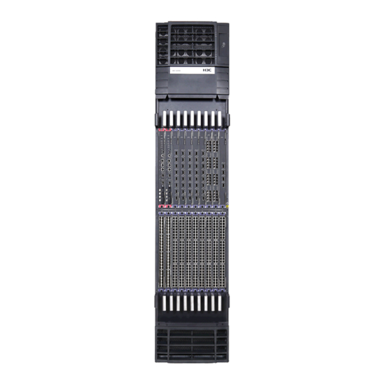
The line card slots are for both Ethernet interface cards and OAA cards. For card specifications, see • “Appendix A Hardware specifications.” • Unless otherwise stated, the configuration and installation procedures in this document apply to all S12500 switches. Physical architecture NOTE: The DC-powered model and the AC-powered model of a chassis look the same. •... - Page 13 S12508 chassis views Figure 1 S12508 front view (1) Power frame cover (2) Upper cabling rack (3) MPU slots (slots 0 and 1) (4) Lower cabling rack (5) System air intake vents (6) ESD-preventive wrist strap port (7) Line card slots (slots 2 to 9) NOTE: The power frame cover protects the power supply air filter and the power frame slot.
- Page 14 Figure 2 S12508 rear view (1) Power entry module (PEM) (2) Upper fan tray (3) Lower fan tray (4) Ventilation panel (5) Grounding screw (6) ESD-preventive wrist strap port (7) Switching fabric module slots (slots 10 to 18) (8) System air exhaust vents (9) Power air exhaust vents The S12508 chassis has the following slots and components: Two MPU slots and eight line card slots at the front, and nine switching fabric module slots at the...
- Page 15 S12518 chassis views Figure 3 Front view of the S12518 (1) Power frame cover (2) Upper cabling rack (3) MPU slots (slots 0 and 1) (4) Line card slots (slots 2 to 19) (5) Lower cabling rack (6) System air intake vents (7) ESD-preventive wrist strap port...
- Page 16 Figure 4 S12518 rear view (1) Power entry module (PEM) (2) Upper fan tray (3) Switching fabric module slots (slots 20 to 28) (4) Lower fan tray (5) Ventilation panel (6) Grounding screw (7) ESD-preventive wrist strap port (8) System air exhaust vents (9) Power air exhaust vents The S12518 chassis has the following slots and components:...
-
Page 17: Fan Tray
• Backplane The backplane of an S12500 switch is located inside the chassis. It provides high-speed data switching between switching fabric modules and line cards, and exchanges management and control signals between MPUs and line cards/switching fabric modules. The backplane provides the following capabilities: Provides communication channels for signal exchange between cards. - Page 18 Figure 5 S12508 fan tray Table 2 Description of fan LEDs Color Status Description The fan tray has failed. Green Flashing The fan tray is operating normally. The fan tray is in a normal state. Flashing The fan tray is faulty. The fan tray is faulty.
- Page 19 Figure 6 Ventilation inside an S12508 chassis (1) System air intake direction (2) System air exhaust direction (3) Power supply air intake direction (4) Power supply air exhaust direction...
- Page 20 Figure 7 Ventilation inside an S12518 chassis (1) System air intake direction (2) System air exhaust direction (3) Power supply air intake direction (4) Power supply air exhaust direction...
-
Page 21: Power Supply System
Power supply system The S12500 Routing Switch Series provides both AC powered chassis and DC powered chassis. You can select power supply and the number of power supplies as needed. Figure 8 Power frame appearance (without any power supply) AC power supply... - Page 22 Table 3 Description of the LEDs on the power monitoring module Color Status Description The power monitoring module is working normally. Green The power monitoring module is faulty. • At least one power supply is faulty. • All power supplies have been removed from the power frame.
- Page 23 Color Status Description Power is being correctly output. Output Green No power is being output. Flashing The power output is overloaded. The AC power supply is experiencing an over-temperature condition. Service Yellow The AC power supply is operating properly. The AC power supply is faulty. Fault The AC power supply is operating properly.
-
Page 24: Dc Power Supply
2, 4, and 6 in the bottom row, from left to right. DC power supply The DC-powered chassis of the S12500 Routing Switch Series use the PSE9000-D DC power supply system, which comprises DC power frames, DC power supplies, and power monitoring modules. DC power frame Each DC power frame can have one power monitoring module and up to six DC power supplies. - Page 25 Figure 13 DC power frame rear view (1) A pair of wire posts (2) Grounding post NOTE: The DC power frame has a cover to protect the wire posts and grounding post. DC power supply Figure 14 DC power supply (1) Power input LED (2) Power output LED (3) Over-temperature alarm LED...
- Page 26 Item Description Startup voltage range –44 VDC to –72 VDC Max input current 60 A Max output power 1800 W Power monitoring module The power monitoring module is vertically installed between the power supply slot area and the power switch. It monitors the alarm status, in-position status, and operating status of the power supplies in real time.
-
Page 27: Preparing For Installation
Installation tools Safety recommendations To avoid possible bodily injury and equipment damage, read the safety recommendations in this chapter carefully before installing an H3C S12500 switch. The recommendations do not cover every possible hazardous condition. This section includes these topics: •... -
Page 28: Esd Prevention
Make sure that the ESD-preventive wrist strap is well grounded. Step4 Figure 15 Use an ESD-preventive wrist strap Safety with switch moving When moving an H3C S12500 switch, perform the following steps: Remove all the external cables (including the power cables) before moving the chassis. • •... -
Page 29: Examining The Installation Site
The laser inside the optical fiber may hurt your eyes. Examining the installation site The H3C S12500 Routing Switch Series can only be used indoors. To ensure that the switch works normally and to prolong its service lifetime, the installation site must meet the following requirements: Weight support requirements •... -
Page 30: Humidity Requirements
CAUTION: If condensation appears on the switch when you move it to a high-temperature environment, dry the switch before powering it on to avoid short circuits. Humidity requirements Maintain appropriate humidity in your equipment room, as described in Table Table 9 Humidity requirements Humidity Range Operating humidity (noncondensing) -
Page 31: Emi Requirements
Make sure that the resistance between the chassis and the ground is less than 1 ohm. Power supply requirements Perform the following steps to satisfy the power supply requirements of the S12500 Routing Switch Series: Calculate the system power consumption. -
Page 32: Rack-Mounting Requirements
For adequate ventilation and ease of maintenance, do not place the switch close to the wall, and • make sure the front and rear clearances are at least 0.8 m (2.62 ft). Rack-mounting requirements To mount the switch in a rack, adhere to the following requirements: Use a four-post 19 inch standard rack. -
Page 33: Installation Tools
Figure 17 Rack depth The rack is available with standard slide rails (or rack shelves), cage nuts, and screws. • The slide rails (or rack shelves) can support the weight of the switch chassis and its accessories. • The rack can be well grounded. •... - Page 34 NOTE: The number of screws and nuts supplied with the switch depends on those shipped from the factory. User-supplied tools and equipment Mechanical lift • • Cross-head screwdriver P1 – 100 mm, P2 – 150 mm and P3 – 250 mm Flat screwdriver P4 –...
-
Page 35: Installing The Switch
Installing the switch This chapter includes these sections: Installation flow • Check before installation • Installing the switch in a rack • • Installing the switch on a workbench Grounding the switch • Installing the power system • Installing a fan tray •... -
Page 36: Installation Flow
Install cards Connect the power cords Verify the installation Check before installation Check the following before installing an H3C S12500 switch: • Make sure that you have read “Preparing for Installation” carefully and the installation site meets all the requirements. -
Page 37: Installation Preparation
Before installing the slide rails, check that the slide rails can support the weight of the switch. For the • weights of the S12500 Routing Switch Series, see the chapter “Appendix A Technical specifications.” • Besides slide rails, you can use a rack shelf to support the switch. This document describes how to install slide rails only. - Page 38 Figure 19 Install the slide rails (1) Middle of the narrower metal area between holes (2) 1 RU NOTE: The appearance and installation methods of slide rails depend on the slide rail types. • To ensure stability of the rack, install the slide rails to the lowest possible position when installing a single •...
-
Page 39: Installing The Mounting Brackets
Figure 20 Install the cage nuts NOTE: When preparing for installation, make sure that the total height of the switches to be installed is no higher than the height of the rack, and reserve enough clearance for cable routing. Installing the mounting brackets Attach the mounting brackets onto the left and right sides of the switch, as shown in Figure... -
Page 40: Installing An Air Deflector (Optional)
Installing an air deflector (optional) An air deflector is shipped with the S12500 switches. You can install the air deflector at the rear of the chassis (where a ventilation panel is located) to block the airflow from entering the rear of the chassis. -
Page 41: Installing A Chassis Air Filter (Optional)
Chassis air filters are installed at the air intake vents to prevent dust from entering the chassis. Chassis air filters of the S12500 Routing Switch Series are optional. You can order them as needed. If you have ordered chassis air filters, H3C recommends you to install the air filters before mounting the switch to the rack. - Page 42 Figure 23 Install the front air filter Follow these steps to install the rear air filter on an S12508: Loosen the captive screws on the ventilation panel and remove it. Step1 Unpack the air filter and attach it to where the ventilation panel was located, and then fasten the captive Step2 screws on the air filter.
-
Page 43: Mounting The Switch In The Rack
Figure 25 Install an air filter Mounting the switch in the rack NOTE: • Make sure that you have installed slide rails or a rack shelf on the rack for supporting the switch. The slide rails or rack shelf should be sturdy enough to support the weight of the switch chassis and all accessories. -
Page 44: Verifying The Installation
NOTE: If the screw holes on the mounting brackets cannot align with the cage nuts on the rack, check that the bottom edge of the slide rail aligns with the middle of the narrowest metal area between holes and that the cage nuts are installed in the correct holes. - Page 45 NOTE: Each circled area in Figure 27 shows two rows of installation holes. You can select either row of a circled area to install the mounting brackets. Figure 27 Install the mounting brackets (1) Mounting bracket installation holes (2) Mounting bracket Fix the switch to the workbench or ground with L-shaped brackets, as shown in Figure Step4...
-
Page 46: Grounding The Switch
Figure 28 Install L-shaped brackets (1) L-shaped bracket (2) Wall anchor (3) Mounting screw Grounding the switch WARNING! For the safety of operators and equipment, securely ground the switch. Make sure that the resistance reading between the switch chassis and the ground is less than 1 ohm. Most racks are equipped with a grounding strip. -
Page 47: Installing The Power System
Connect the grounding cable to the earthing system in the equipment room. Do not connect it to a fire main or lightning rod. Installing the power system The S12500 Routing Switch Series supports both AC and DC power supply. You can select either AC or DC power supply as needed. This section includes these topics: •... -
Page 48: Installing A Dc Power Supply
CAUTION: Hold a power entry module (PEM) or power supply by the bottom when moving it. Never attempt to lift • a PEM or power supply with its handle because the handle is not designed to support weight. Doing so might result in bodily injury or damage to the module. -
Page 49: Installing An Ac Power Supply
Figure 30 Install a power supply Installing an AC power supply To install an AC power supply, follow these steps: • Installing a PEM Installing an AC power supply • Installing a PEM Follow these steps to install a PEM: Loosen the screws on the filler panel of the PEM slot with a Phillips screwdriver to remove the filler panel. -
Page 50: Installing A Fan Tray
Figure 31 Install a PEM NOTE: Gently insert the PEM into the chassis to avoid damaging the connector at the end of the PEM. Installing an AC power supply IMPORTANT: Make sure that the number of power supplies is sufficient for the switch to operate properly. •... -
Page 51: Installing A Card
Install at least one MPU, one line card, and seven switching fabric modules on an S12508 or S12518. The S12500 does not support intermixing of the MPU, line card, and switching fabric modules. Use one of the following positions to install the card: Install MPUs, Ethernet interface cards, and OAA cards at the front of the switch chassis. -
Page 52: Installation Procedure
NOTE: Keep the removed the blank panel and protective box properly for future use. • • All the cards for the S12500 are hot-swappable. Installation procedure Follow these steps for installation: Remove the protective box before installing an MPU: Step1 Put on an ESD-preventive wrist strap and then loosen the captive screws that fix the MPU to the •... -
Page 53: Connecting Power Cords
Figure 34 Remove the protective box Move the ejector levers of the MPU outwards, hold the MPU by the handle, and push the MPU into the Step2 slot along slide rails slowly. Push the ejector levers inward to ensure close contact between the MPU and the backplane. Step3 Position the screws into the holes and fasten them with a screwdriver to fix the MPU. -
Page 54: Connecting An Ac Power Cord
Follow these steps before connecting power cords: For lightning protection, the AC power should be led through an external lightning device into • S12500 Routing Switch Series. For more information, see the chapter “Appendix D Lightning protection of the switch.” •... -
Page 55: Connecting A Dc Power Cord
Six pairs of wiring terminals (marked PSR1 through PSR6) are available on the DC grounding strip of the S12500 switches. The wiring terminals correspond to the power supplies 1 through 6, respectively. The power source supplies power to the switch through the wiring terminals. If slot 1 is installed with a power supply, the wiring terminals marked PSR1 must be connected to the power source with a DC power cord to make the power supply operate properly. - Page 56 Connect one end of the blue DC power cord marked with – to the negative terminal (–) on the power Step4 supply; connect the – end of the grounding cable to the terminal marked with PE on the rightmost of the grounding strip.
- Page 57 Figure 38 Connect the other end of the DC power cord to the grounding strip Put the protection cover on the wiring terminals. Step6 Figure 39 Install the protection cover Verifying the installation WARNING! Make sure that you have turned off the power before checking the installation to avoid bodily injury and switch damage.
- Page 58 Table 13 Installation checklist Result Item Remarks The grounding cable is correctly grounded. Fan trays are correctly installed and make close contact with the backplane. Power supplies are correctly installed and have close contact with the frames. The power switch is off (the power switch is at the OFF position).
-
Page 59: Connecting The Switch To The Network
Connecting the switch to the network This chapter includes these sections: Logging in to the switch • Connecting the switch to the network • Cable routing recommendations • Logging in to the switch Logging in through the console port is the most common way to log in to a switch. It is also the prerequisite to configuring other login methods. - Page 60 RJ-45 pin Signal DB-9 pin Signal Connection procedure Figure 41 Connect the switch and the PC through the console port Follow these steps to connect the console cable: Connect the DB-9 connector of the console cable to the serial port of a PC or terminal. Step1 Connect the RJ-45 connector of the console cable to the console port of the MPU of the switch.
-
Page 61: Setting Up A Configuration Environment
Setting up a configuration environment Follow these steps to set up a configuration environment: Launch a terminal emulation utility (such as HyperTerminal in Windows XP/Windows 2000). Select Step1 Start > All Programs > Accessories > Communications > HyperTerminal to access the HyperTerminal window. - Page 62 Figure 43 Select a port for the HyperTerminal connection Set serial port parameters. Set the bits per second to 9600, data bits to 8, parity to None, stop bits to 1, Step3 and flow control to None. Figure 44 Set serial port parameters Click OK to enter the HypterTerminal window, as shown in Figure Step4...
- Page 63 Select File > Properties in the HyperTerminal window to access the Properties window. Click Settings in Step5 the Window (as shown in Figure 46), select VT100 for terminal emulation, and click OK. NOTE: H3C recommends that you select the Windows keys option button.
-
Page 64: Powering On The Switch
Figure 46 Set the terminal emulation parameters Powering on the switch Power-on checklist Before powering on the switch, confirm the following preparations: The interface cables, power cables, and the grounding cable are correctly connected. • • The power outlet voltage is the same as indicated on the switch label. The console cable is correctly connected, the console terminal or PC is powered on, and the •... - Page 65 Booting Normal Extend BootWare The Extend BootWare is self-decompressing Done! ************************************************************************** H3C S12500 BootWare, Version 1.09 ************************************************************************** Copyright (c) 2004-2009 Hangzhou H3C Technologies Co., Ltd. Compiled Date : Jul 22 2009 CPU Type : MPC8548E CPU L1 Cache : 32KB...
-
Page 66: Verification (Recommended)
Press Enter to begin configuring the switch at the prompt: <H3C> NOTE: The S12500 Routing Switch Series provides a command line interface (CLI). For more information about • H3C S12500 Routing Switch Series Fundamentals Configuration Guide. the CLI, see the The output depends on your switch model. -
Page 67: Connecting The Switch To The Network Through The Aux Port
TIP: After connecting the switch to the network, you can use the ping or tracert command to check the H3C S12500 Routing interoperability between the switch and network. For more information, see the Switch Series Network Management and Monitoring Command Reference Connecting the switch to the network through the AUX port You need an AUX cable when configuring a switch with the remote modem dial-up approach. - Page 68 Plug the DB-9 (male) connector at the other end into the serial port of the modem. Step2 Connecting the switch to the network through a copper Ethernet port The 10/100/1000Base-T electrical ports of the switch support MDI/MDI-X auto-sensing. They are connected to the network through category-5 or above twisted pairs that are equipped with RJ-45 connectors.
- Page 69 Remove the protective cap from the fiber connector, and use dust free paper and absolute alcohol to Step2 clean the end face of the fiber connector. Connect one end of the fiber to the SFP module of the S12500 switch. Step3 Connect the other end of the fiber to the peer device.
-
Page 70: Sfp Module
Figure 49 Connect an optical fiber to an SFP module LC plug SFP module Connect an SFP+ cable (optional) When connecting SFP+ ports located near each other, besides SFP+ transceiver module and optical fiber, you can use an SFP+ cable. Figure 50 SFP+ cable (1) Connector (2) Pull latch... -
Page 71: Cable Routing Recommendations
A fiber management tray (FMT) is installed in a cabinet for winding redundant fibers between the S12500 and other devices. Preparations Confirm the following prerequisites: • The cabinet is fixed. The switch is installed. • The installation involves the following materials: •... - Page 72 CAUTION: Long cables can be bound with cable ties. Do not bind cables at the air exhaust vent to prevent the • cables from aging too fast. For more information, see the chapter “Appendix E Cable management.” Fix cables as near the switch as possible. The cables between the fixing point and switch interfaces must •...
-
Page 73: Hardware Management
# Display the electrical label information of the card in slot 3 on your switch. In standalone mode: <Sysname> display device manuinfo slot 3 DEVICE_NAME : LST1MRPNC1 DEVICE_SERIAL_NUMBER : 210231A9680089000004 MAC_ADDRESS : 000F-E212-3400 MANUFACTURING_DATE : 2009-02-27 VENDOR_NAME : H3C In Intelligent Resilient Framework (IRF) mode:... -
Page 74: Displaying The Card Information Of Your Switch
1 slot 3: DEVICE_NAME : LST1MRPNC1 DEVICE_SERIAL_NUMBER : 210231A9680089000004 MAC_ADDRESS : 000F-E212-3400 MANUFACTURING_DATE : 2009-02-27 VENDOR_NAME : H3C Table 16 display device manuinfo command output description Field Description DEVICE_NAME Card name DEVICE_SERIAL_NUMBER Card serial number MAC_ADDRESS MAC address of the switch... - Page 75 In IRF mode: Slot No. Brd Type Brd Status Subslot Num Sft Ver NONE Absent NONE LST1MRPNC1 Master S12500-CMW520-A1221 NONE Absent NONE NONE Absent NONE NONE Absent NONE LST1GT48LEC1 Normal S12500-CMW520-A1221 NONE Absent NONE NONE Absent NONE NONE Absent NONE...
-
Page 76: Rebooting Your Switch
Rebooting your switch When a fault occurs to a running switch, you can remove the fault by rebooting the switch. To reboot a switch, use one of the following methods: • Power on the switch after powering it off, which is also called hard reboot or cold start. Powering off a running switch causes data loss and hardware damages, and therefore this method is not recommended. -
Page 77: Managing The Power Supply System
MAC_ADDRESS : NONE MANUFACTURING_DATE : 2010-01-20 VENDOR_NAME : H3C # Display the electrical label information of power monitoring module 2 on member switch 1 in IRF mode. <Sysname> display device manuinfo chassis 1 power-monitor 2 Chassis 1: Power Monitor unit 2:... -
Page 78: Configuring The Number Of Redundant Power Supplies
To do… Use the command… Remarks Enable power supply management Required power-supply policy enable on a specified member switch (IRF chassis chassis-number Enabled by default mode) Configuring the number of redundant power supplies Redundant power supplies are reserved for power supply backup and power supply threshold alarming. With multiple redundant power supplies configured in the system, if a power supply fails or the system power supply is overloaded, the system automatically enables a redundant power supply. -
Page 79: Allocating Ids For Ac Power Supplies
Follow a step below to start or stop power supply to a card: To do… Use the command… Remarks Optional Start or stop power supply to The specified card cannot be a the specified card power-supply { on | off } slot slot-number main board or a switching fabric (standalone mode) module. - Page 80 Figure 52 Power supply slot numbers for the S12508 Figure 53 Power supply slot numbers for the S12518 After the power-supply led-blink command is executed, the LED of the corresponding power supply blinks for a period of time to show you the location of the power supply. You can configure the time when the LED blinks and how long the LED keeps blinking.
-
Page 81: Displaying The Power Supply System Information Of Your Switch
CAUTION: Each AC power supply can be allocated with only one ID, and multiple AC power supplies cannot have the same ID. Displaying the power supply system information of your switch Use the display power-supply command to display your switch’s power supply system information, including whether power management is enabled, the number of configured redundant power supplies, power, output voltage and current, and whether each card is powered on. - Page 82 1.00 PSU Status: ID Status Input-Err Output-Err High-Temperature Fan-Err Closed Current-Limit -- ------- ----------- ---------- ---------------- ------- ------ ------------- 1 Absent 2 Normal 3 Normal 4 Normal 5 Normal 6 Normal 7 Normal 8 Normal 9 Normal 10 Absent 11 Normal 12 Normal Line-card power status: Slot...
- Page 83 SYSTEM POWER USED(CURRENT): 470.00 Watts System power monitoring unit: Software version: 100 Type In/Out Rated-Vol(V) Existing Usable Redundant(actual) ---------- ------ ------------ -------- ------ ----------------- PSE9000 AC/DC 220(default) DC output voltage information: Tray Value(V) Upper-Threshold(V) Lower-Threshold(V) Status ---- -------- ------------------ ------------------ ------- 50.00 53.00...
- Page 84 Line-card power status: Slot Board-Type Watts Status ---- --------------- ----- ------ None Absent None Absent None Absent None Absent None Absent None Absent LST1GT48LEC1 None Absent None Absent None Absent None Absent None Absent None Absent None Absent None Absent None Absent None...
- Page 85 8.60 PSU Status: ID Status Input-Err Output-Err High-Temperature Fan-Err Closed Current-Limit -- ------- ----------- ---------- ---------------- ------- ------ ------------- 1 Absent 2 Absent 3 Absent 4 Normal 5 Absent 6 Absent Line-card power status: Slot Board-Type Watts Status ---- --------------- ----- ------ None...
-
Page 86: Configuring Temperature Alarm Thresholds For A Card
Field Description Power supply model: • Type PSE9000: Old-model AC power system • PSE9000-A: New-model AC power system In/Out Input/output current type Rated-Vol(V) Rated voltage, in watts Existing Total number of power supplies Usable Number of power supplies being used Redundant(actual) Number of redundant power supplies Tray... -
Page 87: Displaying The Temperature Information Of Your Switch
Follow these steps to configure temperature alarm thresholds for a card: To do… Use the command… Remarks Enter system view system-view — Configure temperature alarm temperature-limit slot slot-number { inflow | hotspot thresholds for a card (standalone | outflow } sensor-num LowerLimit WarningLimit Optional mode) [ AlarmLimit ]... -
Page 88: Isolating A Card And Locating Card Faults
Field Description Temperature sensor: • hotspot: Hotspot temperature sensor Sensor • inflow: Inflow temperature sensor • outflow: Outflow temperature sensor Temperature Current temperature Lower limit Lower limit of temperature WarningLimit Upper limit of temperature for warning AlarmLimit Upper limit of temperature for alarming Upper limit of temperature for shutting down the switch ShutdownLimit (currently not supported) -
Page 89: Configuring In-Service Hardware Failure Diagnosis And Failure Protection
For example, you can see flash:/diag_slot3_20080522_103458.txt. • Deliver the fault detection information to the H3C technical engineers or engineers of the sales agent. Configuring in-service hardware failure diagnosis and failure protection A hardware failure may cause traffic forwarding failures and service interruption. - Page 90 Follow these steps to configure in-service hardware failure diagnosis and failure protection: To do… Use the command… Remarks Enter system view system-view — Required The fix actions taken in case of hardware failures include the following ones: • off: Takes no action. •...
-
Page 91: Displaying The Operating State Of Fans
NOTE: If a port is automatically shut down due to hardware failure protection, its status displayed with the • display interface command is Protect DOWN. To bring up the port, use the undo shutdown command on the port. If a card is isolated or its software is not allowed to be loaded due to hardware failure fix operations, •... -
Page 92: Displaying The Alarming Information Of A Card
CPLD version: 001 Fan number: 12 Temperature: 26 C High temperature alarm threshold: 60 C Low speed alarm threshold: 1450 rpm Status Speed(rpm) ---------- ---------- normal 4300 normal 4350 normal 4050 normal 4350 normal 4350 normal 4350 normal 4400 normal 4100 normal 4200... - Page 93 [ interface-type interface-number ] transceivers only a specified interface NOTE: You can use the Vendor Name field in the prompt information of the display transceiver command to identify an H3C-customized transceiver. If the field is H3C, it is considered an H3C-customized transceiver.
- Page 94 H3C devices: Device model is displayed. Ordering Name • Other devices: N/A is displayed. # Display the electrical label information of the H3C-customized transceiver plugged in interface GigabitEthernet 3/0/19. <Sysname> display transceiver manuinfo interface Gigabitethernet 3/0/19 GigabitEthernet3/0/19 transceiver manufacture information:...
- Page 95 The system outputs alarm information for you to locate and troubleshoot faults of transceivers. H3C-customized transceiver system can also monitor the key parameters of a transceiver, such as temperature, voltage, laser bias current, TX power, and RX power. When these parameters are abnormal, you can take corresponding measures to prevent transceiver faults.
- Page 96 Field Remarks TX bias high TX bias current is high. TX bias low TX bias current is low. Temp high Temperature is high. Temp low Temperature is low. Voltage high Voltage is high. Voltage low Voltage is low. Transceiver info I/O error Transceiver information read and write error Transceiver info checksum Transceiver information checksum error...
- Page 97 Transceiver type not Transceiver type is not supported on the port. supported by port hardware # Display the currently measured values of the fault detection parameters of the H3C-customized transceiver plugged in interface GigabitEthernet 3/0/1. <Sysname> display transceiver diagnosis interface Gigabitethernet 3/0/1...
-
Page 98: Troubleshooting
Troubleshooting This chapter describes how to troubleshoot the S12500 switch installation failures. The power supply system, fans, and cards of an S12500 switch have multiple LEDs, through which you can locate the failures. This chapter includes these sections: Configuration terminal problems •... -
Page 99: Power Supply System Failure
Unplug and then plug the power monitoring module. Step1 If the RUN LED is still off, replace the power monitoring module. Step2 If the RUN LED is still off, contact H3C Technical Support for help. Step3 Power supplies Figure 54 LEDs on an AC power supply... - Page 100 Figure 55 LEDs on a DC power supply (1) Input status LED (2) Output status LED (3) Over-temperature alarm LED (4) Fault LED Table 28 Description of power supply LEDs Color Status Description The power is input properly. Input status LED Green No power is input.
-
Page 101: Fan Failure
Fan failure Table 29 Description of fan LEDs Color Status Description The fan tray fails. Green Flashing The fan tray is operating properly. The fan tray is in a normal state. Flashing The fan tray is faulty. The fan tray is faulty. When the RUN LED is off or the ALM LED is on or flashing, the fan fails. -
Page 102: Lpu Failure
When the MPU works properly, the RUN LED (callout 7 in Figure 56) flashes in green. When the RUN LED is off, steady on, or flashes in red, the MPU fails. Follow these steps to troubleshoot the MPU: Check that the power supply works properly. For more information, see “Power supply system failure.”... -
Page 103: Interface Failure
When the two LEDs are not in the states mentioned above, the switching fabric module fails. Follow these steps to troubleshoot the switching fabric module: Check that the MPU works properly. For more information, see “MPU failure.” Step1 Use the display device command to check whether the software version is compatible with the switching Step2 fabric module in the current slot. - Page 104 • • Brief problem description Brief explanation of the troubleshooting measures that have been taken • You can contact the customer service through the customer service hotline, the H3C website, or email. Customer service hotline: 400-810-0504 Website: http://www.h3c.com E-mail: customer_service@h3c.com...
-
Page 105: Replacement Procedures
Removing, cleaning, and installing the air filters The air filters of an S12500 switch fall into the following types: Chassis air filter—No chassis air filter is shipped with the S12500 chassis by default. You can order • one as needed. - Page 106 Figure 57 Remove the front chassis air filter of a S12508 chassis Remove, clean, and install a rear chassis air filter Follow these steps to remove, clean, and install a rear chassis air filter: Loosen the captive screws at both sides of the rear chassis air filter, and remove the rear chassis air filter. Step1 Take off the sponge at the rear of the chassis air filter.
-
Page 107: Removing, Cleaning, And Installing A Power Supply Air Filter
Figure 59 Remove the air filter for an S12518 Removing, cleaning, and installing a power supply air filter The power supply air filter of an S12500 switch is right behind the front panel of the power frame to prevent dust from entering the power frame. -
Page 108: Replacing A Power Supply
Replacing a power supply WARNING! Power supplies for the S12500 are hot-swappable. When installing and replacing a power supply with the switch powered on, pay attention to the operation procedures and electricity safety issues. To avoid injury, do not touch any wires, terminals, and parts with a high-voltage hazard sign. -
Page 109: Replacing A Pem (Applicable To Only An Ac Power Supply)
Figure 61 Replace a power supply Replacing a PEM (applicable to only an AC power supply) Follow these steps to replace a PEM: Use a Philips screwdriver to loosen the screws on the front panel of the PEM. Step1 Slowly pull the PEM out along the slide rails, as shown in Figure Step2 Put the removed PEM on an antistatic mat or in its original shipping materials. -
Page 110: Replacing A Card
Figure 62 Remove the PEM Figure 63 Install the PEM Replacing a card Preparing for the replacement NOTE: Keep the removed blank panel and protection cover properly for future use. Follow these steps to prepare for the replacement: Put on an ESD-preventive wrist strap, and make sure that the wrist strap makes good skin contact and is Step1 well grounded. - Page 111 Remove the network cables and power cords from the card to be removed. Step3 Replacement procedure All cards of the S12500 are hot-swappable. Follow these steps to replace a card: Loosen the captive screws on the card. Step1 Move the ejector levers outwards to separate the card from the backplane.
-
Page 112: Replacing A Fan Tray
Figure 65 Replace a card A: Card to be removed B: Card to be installed Replacing a fan tray CAUTION: To avoid injury, do not touch any wires, terminals, and parts with a high-voltage hazard sign. • Fan trays are hot-swappable. To replace a fan tray with the switch running, pull out the fan tray after it •... -
Page 113: Replacing A Cf Card
Replacement procedure Follow these steps to replace a fan tray: Loosen the captive screws on the fan tray. Step1 Pull out the fan tray along the slide rails. Put the removed fan tray in an antistatic bag or in its original Step2 shipping materials. - Page 114 The CompactFlash (CF) card is installed on the MPU of an S12500. When the CF card memory is insufficient or the CF card is damaged, follow these steps to replace the CF card: Check the CF card LED status. Step1 If the LED is on, you cannot remove the CF card.
-
Page 115: Replacing A Transceiver Module
Figure 68 Replace a CF card Replacing a transceiver module The replacement procedures of XFP, SFP+, and SFP transceiver modules are similar. This section takes an SFP transceiver module as an example. CAUTION: When installing or removing an SFP transceiver module, do not touch the golden finger of the SFP transceiver module. - Page 116 Figure 69 Remove an SFP transceiver module Figure 70 Install an SFP transceiver module NOTE: Remove the fibers, if any, from the SFP transceiver module before installing it.
-
Page 117: Regulatory Compliance And Safety Information
Regulatory Compliance and Safety Information Regulatory Compliance Information Regulatory Compliance Standards Table 31 Regulatory compliance standards Discipline Standards FCC Part 15 (CFR 47) CLASS A ICES-003 CLASS A VCCI-3 CLASS A CISPR 22 CLASS A EN 55022 CLASS A AS/NZS CISPR22 CLASS A CISPR 24 EN 55024 EN 61000-3-2... -
Page 118: European Directives Compliance
Directive and must be disposed of in a responsible manner. USA Regulatory Compliance FCC Part 15 H3C S12500 Series Routing Switches comply with Part 15 of the FCC Rules. Operation is subject to the following two conditions: This device may not cause harmful interference. -
Page 119: Cispr 22 Compliance
CISPR 22 Compliance H3C S12500 Series Routing Switches comply with the requirements of CISPR 22 for Class A Information Technology Equipment (ITE). Warning: If this equipment is used in a domestic environment, radio disturbance may arise. When such trouble occurs, the user may be required to take corrective actions. - Page 120 Note Before any operation is performed, please read the operation instructions and precautions carefully to minimize the possibility of accidents. The Note, Caution, Warning and Danger items in other manuals do not cover all safety precautions that should be followed. They are only the supplements to the safety precautions for operations as a whole.
- Page 121 Die Symbole in diesem Handbuch verwendeten sind in der folgenden Tabelle dargestellt. Diese Symbole sollen das Personal während der Installation und Instandhaltung der Ausrüstung an die Wichtigkeit der im Handbuch aufgeführten Sicherheitsvorschriften erinnern. 以下表格中的安全标识,是用来提示读者在进行设备安装和维护时的安全预防要求。 Table 32 Safety symbol and description Sicherheitssymbole und Beschreibung 安全标识和描述 Safety Symbol Description Symbole...
- Page 122 Sorgen Sie dafür, dass die Öffnungen der Ventilation zu keinem Zeitpunkt verschlossen, verstopft • oder anderweitig blockiert sind. Zwischen den Ventilationsöffnungen und Wänden bzw. anderen Gegenständen muss stets ein Abstand von mindestens 5cm bestehen. • 设备在工作时必须确保通风口的畅通, 确保设备离墙壁或是其它的可能堵塞通风口的物体的间距 至少 5cm。 Never defeat the ground conductor or operate the equipment in the absence of a suitably installed •...
-
Page 123: Electricity Safety Elektrische Sicherheit
Do not touch the fan before it stops rotating, as its blades will keep running due to inertia even if the • fan module has been powered off. • Berühren Sie nicht den Lüfter vor seinem kompletten Stoppen, weil seine Blätter wegen des Beharrungsvermögens drehen werden, auch wenn die Lüftermodule ausgeschaltet ist. - Page 124 • 在潮湿环境下进行安装时,请避免液体进入设备。 Warning Non-standard and improper high voltage operations may result in fire and electric shock. Therefore, AC cable bridging and wiring through a certain area must follow the local rules and regulations. The personnel who perform high voltage operations should be qualified for high voltage and AC operations. Warnung Die Nichtbeachtung der Sicherheitsvorschriften bei der Arbeit mit Hochspannung kann zu Feuer und elektrischem Schlag führen.
-
Page 125: Lithium Battery Lithiumbatterie
Anmerkung Für mit Gleichstrom betriebene Ausrüstung benutzen Sie bitte eine 10 mm oder 6 AWG Zuleitung. Für mit Wechselstrom betriebene Ausrüstung benutzen Sie bitte eine 2.5 mm oder 12 AWG Zuleitung, oder 1.5 mm oder 14 AWG Zuleitung Komponenten. 说明 DC 电源设备,请使用... -
Page 126: Fuse Sicherung
Achtung Entsorgen Sie die Lithiumbatterien auf keinen Fall durch Verbrennen! 注意 请勿将锂电池置入火中。 Fuse Sicherung保险丝 Warning For the safety of continuous operation, please replace the fuse with that of the same type and rating, if necessary. Warnung Ersetzen Sie die Sicherung bei Bedarf immer nur mit einem Sicherungstyp, der die gleichen technischen Daten besitzt. -
Page 127: Appendix A Technical Specifications
Appendix A Technical specifications Environment requirements Table 33 Environment requirements Temperature Range Long term: 0°C to 40°C (32°F to 104°F) Short term: –10°C to +50°C (14°F to 122°F) (no more Operating temperature than 96 hours of continuous operation in less than 15 days in one year) Operating humidity (noncondensing) 5% to 95%... - Page 128 NOTE: Net weight refers to the weight of the chassis (with filler panels installed), excluding fan trays, cards, and • power modules. Full configuration refers to the maximum weight of the switch when all cards and power modules are • installed to the switch.
-
Page 129: Fan Trays
Line card model Power consumption Net weight Dimensions (H × W × D) 40 × 400 × 467 mm (1.57 × LST1FW2A1 90 W to 120 W 4.36 kg (9.61 lb) 15.75 × 18.39 in) 40 × 400 × 467 mm (1.57 × LST1IPS1A1 90 W to 120 W 4.36 kg (9.61 lb) -
Page 130: Switch Ordering Guide
LST1MRPNC All S12500 S12500 MPU 1 to 2 models LST1SF08B1 S12508 7 to 9 Switching fabric LST1SF18B1 S12500 switching fabric module S12518 7 to 9 module LST1SF18C1 S12518 7 to 9 Standard Ethernet All S12500 interface LST1XP8LEB1 As required... - Page 131 Applicable Supported Category Model Description S12500 number chassis Advanced LST1XP8LEF1 8-port 10 Gbps optical Ethernet interface card Standard LST1XP4LEB1 4-port 10 Gbps optical Ethernet interface card Enhanced LST1XP4LEC1 4-port 10 Gbps optical Ethernet interface card Standard LST1GP48LEB 48-port 1000 Mbps optical Ethernet...
-
Page 132: Switching Fabric Modules
NOTE: H3C recommends you to install two MPUs for redundancy, and install all switching fabric modules to • your switch. For more information about the S12500 card LEDs, see the chapter “Appendix B LEDs.” • For more information about the S12500 cards, see the corresponding datasheet of the cards. -
Page 133: Ethernet Interface Card Specifications
Ethernet interface card specifications Table 42 Ethernet interface card specifications Supported interface Model Number of interfaces Interface type modules 10GBase-R/W XFP/LC optical LST1XP8LEB1 10-GE XFP modules interfaces 10GBase-R/W XFP/LC optical LST1XP8LEC1 10-GE XFP modules interfaces 10GBase-R/W XFP/LC optical LST1XP8LEF1 10-GE XFP modules interfaces 10GBase-R/W XFP/LC optical LST1XP4LEB1... -
Page 134: Power Components Ordering Guide
Choose power supplies based on your actual needs. Make sure that the maximum output power of the power supplies exceeds the system power consumption (H3C recommends reserving a certain power de-rating value). For the maximum output power of a single power supply, see Table H3C recommends you to configure N+1 or N+M power supply redundancy. - Page 135 S12518: 12 at most NOTE: The AC power frame and power monitoring module are integrated to the chassis of S12500 AC models, • so you do not need to order them. You must order the PEM and AC power supplies yourself.
- Page 136 Table 46 16A AC power cords used in different countries or regions Countries or regions where the type of Countries or Other countries or Connector regions seldom power cords conforms Code (Length) regions using this type of type to local safety using this type of power cords regulations and can be...
- Page 137 Countries or regions where the type of Countries or Other countries or Connector power cords conforms regions seldom Code (Length) regions using this type of type to local safety using this type of power cords regulations and can be power cords used legally 0404A060 (3 Malaysia, Singapore,...
- Page 138 Countries or regions Countries or where the type of Other countries or Connector power cords conforms regions seldom Code (Length) regions using this type of type to local safety using this type of power cords regulations and can be power cords used legally 0404A01A (3 I type...
-
Page 139: Appendix B Leds
Appendix B LEDs Power system LEDs Monitoring module LEDs Table 47 Description of the LEDs on the power monitoring module Color Status Description The power monitoring module is working properly. Green The power monitoring module is faulty. • At least one power supply is faulty. •... -
Page 140: Fan Leds
Table 48 Description of power supply LEDs Color Status Description The power is being input normally. Input Green No power is being input. Flashing The input power exceeds the threshold. The power is being output normally. Output Green No power is being output. Flashing The power output is overloaded. -
Page 141: Mpu Leds
MPU LEDs Figure 72 MPU LEDs (1) CF card status LED (CFS) (2) Switching fabric module LED (SFC) (3) LPU status LED (LC) (4) Fan status LED (FAN) (5) Power status LED (PWR) (6) MPU status LED (ACT) (7) MPU status LED (RUN) (8) Network management port LED (LINK) (9) Network management port LED (ACT) -
Page 142: Fan Status Led
Switching fabric module LED Table 52 Description of the switching fabric module LED Status Description Flashing green All the switching fabric modules are working properly. At least one switching fabric module is faulty or no switching Flashing red fabric modules are present. SFC (green-red) The MPU is faulty. -
Page 143: Line Card Leds
MPU LEDs Table 56 Description of MPU LEDs MPU LED Status Description The MPU is in active state. ACT (green) The MPU is in standby state. Flashing green The MPU is working properly. Flashing red RUN (green-red) The MPU is faulty. The MPU is faulty or not in position. -
Page 144: Switching Fabric Module Leds
No link is present. Flashing Data is being transmitted and/or received on the interface. RUN LED NOTE: The RUN LED description of different S12500 line card models is the same. Table 59 Description of the RUN LED Status Description Flashing green The line card works properly. - Page 145 Table 61 Description of the RUN LED Status Description Flashing green The switching fabric module works properly. Flashing red The switching fabric module is faulty. RUN (green-red) The switching fabric module is faulty or not in position.
-
Page 146: Ge Xfp Transceiver Modules
Appendix C Transceiver modules The S12500 Routing Switch Series supports the following transceiver modules: 10-GE XFP transceiver modules • 10-GE SFP+ transceiver modules • 10-GE SFP+ cables • • 100/1000 Mbps SFP transceiver modules 10-GE XFP transceiver modules Table 62 10-GE XFP transceiver module specifications... -
Page 147: Ge Sfp+ Transceiver Modules
10-GE SFP+ transceiver modules Table 63 10-GE SFP+ transceiver module specifications Central Max transmission Model Connector Fiber wavelength distance 62.5/125 μm multimode 33 m (108.27 ft) fiber SFP-XG-SX-MM850-A 850 nm 50/125 μm multimode fiber 300 m (984.25 ft) 62.5/125 μm multimode 220 m (721.78 ft) SFP-XG-LX220-MM13 fiber... - Page 148 Central Max transmission Model Connector Fiber wavelength distance 1490 nm SFP-GE-LX-SM1310-BIDI (Rx)/1310 nm (Tx) 9/125 μm single 10 km (6.21 miles) mode optical fiber 1490 nm SFP-GE-LX-SM1490-BIDI (Tx)/1310 nm (Rx) SFP-GE-LH70-SM1470-CW 1470 nm SFP-GE-LH70-SM1490-CW 1490 nm SFP-GE-LH70-SM1510-CW 1510 nm SFP-GE-LH70-SM1530-CW 1530 nm 9/125 μm single 70 km (43.50 miles)
-
Page 149: Appendix D Lightning Protection Of The Switch
Appendix D Lightning protection of the switch Installation of lightning arrester for AC power (socket strip with lightning protection) If an outdoor AC power cable is directly led to the switch, serially connect the lightning arrester for AC power (Socket Strip with Lightning Protection) before you plug the AC power cable into the switch to prevent the possible damage to the switch due to lightning strike. -
Page 150: Installation Of Lightning Arrester For Network Port
CAUTION: No lightning arrester is shipped with the switch. • Make sure that the arrester is well grounded before using the lightning arrester for power. • After inserting the AC power cable plug of the switch into the socket of the lightning arrester, if the green •... - Page 151 Installation precautions The performance of the port lightning arrester may be affected in the following cases: • The port lightning arrester is installed in reverse direction. Connect the IN end to the outdoor network cable and the OUT end to the network port on the switch. The port lightning arrester is not well grounded.
-
Page 152: Correct Use Of Labels
Appendix E Cable management Correct use of labels Before binding the cables, you should fill in the labels for them correctly and stick them to the right position on the cables. For more information, see the chapter “Appendix F Engineering labels for cables.”... - Page 153 Figure 76 Cable binding example 2 • Bind the cables wherever cable bending cannot be avoided. However, the cable ties cannot be placed inside the bending area in case of the likelihood of cable core break due to excessive stress. See the following figure.
- Page 154 Figure 78 Cable fixing example (1) (1)(2) (1) (1)(2) (1) Flat washer (2) Spring washer (3) Nut When using a hard power cable, fix it near its terminal to free the terminal and the cable from • stress. Do not use tapping screws to fasten the connecting terminals. •...
-
Page 155: Appendix F Engineering Labels For Cables
Appendix F Engineering labels for cables Engineering labels are affixed to both ends of the cables to identify the physical positions of cables on different devices. Labels on the cables facilitate correct and orderly connection of cables, and easy maintenance after the installation. This appendix includes these sections: Introduction to labels •... - Page 156 Label for signal cables The label for signal cables is L-shaped with fixed dimensions, as shown in Figure 79 (expressed in mm). Figure 79 Label for signal cables 84.0 11.0 10.0 11.0 37.0 (1) Dividing line (2) Cut dotted line The dividing lines on the label help to specify more clearly the position of a cable.
-
Page 157: Printing Labels
Printing labels The contents can be printed or written on the labels. Template for printing The Word template is available from H3C for printing labels. When using the template, you can directly modify the contents; note the following rules: •... -
Page 158: Writing Labels
Figure 81 Warning prompt before printing If the printout conforms to the requirement, print it to label paper. If not, adjust the page setup and try printing again, until the correct printout is produced. The method of adjusting the page setup is as follows: Select File >... -
Page 159: Affixing Labels
Table 67 Standard typeface for handwriting Write the characters in the proper size, as shown in Figure Figure 82 Writing direction of the label Affixing labels After printing or writing the label, remove the label from the bottom page and affix it to the signal cable, or the identification plate of the power cable. - Page 160 Figure 84 Fold up the label Cable Cable Stick side Stick side Fold up Fold to right After the printed part of the label has been folded up, the narrow part of the label should be covered completely, as shown in Figure Figure 85 Appearance of affixed labels on signal cables Cable...
-
Page 161: Information Carried On Labels
Figure 86 Appearance of affixed labels on power cables Cable -48V2 Cable Information carried on labels For power cables Labels for power cables are only affixed on one side of the identification plates. On the labels, there is information (the part after the mark “TO:”) about the location of the device on the other end of the cable, like the location of control cabinet, distribution box, or power socket. -
Page 162: Engineering Labels For Ethernet Cables
Remarks When printing/writing and affixing labels, pay attention to keep the labels clean. • Since the label paper is made of moistureproof and waterproof material, do not use ink-jet printers • and ink pens. Labels should be affixed with good order in alignment. •... -
Page 163: Engineering Labels For Optical Fibers
The label on the agent end should contain the serial number of the Ethernet port. The definitions of the cabinet number and frame number are the same as those described in Table 68 above. If it is a stand-alone HUB without any cabinet or frame, the label should contain specific location information that identifies the HUB. -
Page 164: Labels For The Fiber That Connects The Device And The Odf
Table 69 Information on labels affixed to the fiber between two devices Content Meaning Example MN: Cabinet number For example, A01 Numbered in top-down order with two digits, for B: Frame number example, 01 Numbered in top-down and left-right order with C: Physical slot number two digits, for example, 01 MN-B-C-D-R/T... -
Page 165: Engineering Labels For Power Cables
Table 70 Information on labels affixed to the fiber between the device and the ODF Content Meaning Example MN: Cabinet number For example, A01 Numbered in bottom-up order with two digits, for B: Frame number example, 01 Numbered in top-down and left-right order with C: Physical slot number two digits, for example, 01. -
Page 166: Labels For Dc Power Cables
Labels for DC power cables The labels are affixed to the DC cables that provide power for the cabinets, and the protection grounding cables, including the –48V, PGND, and BGND cables. The labels for DC power cables are affixed to one side of the identification plates on cable ties. -
Page 167: Labels For Ac Power Cables
NOTE: In the power distribution box (or the first power cabinet of a row in the transmission equipment room), • every terminal block on the –48V connector bar has a numeric identification. For example, in the above label of “A01/B08--48V2”, “08” (or sometimes “8”) is the numeric identification of the terminal block. PGND and BGND are two copper bars, on which the terminal blocks are short-circuited, therefore •... - Page 168 Figure 92, (1) indicates the label on the loaded cabinet side, which carries the information about the position of the cable on the power socket. (2) indicates the label on the power socket side, which carries the information about the position of the cable on the loaded cabinet side. On the loaded cabinet side, the label marked with “A01-AC”...
- Page 169 Index A B C D E F G I L M P R S T V Grounding the switch,36 About the H3C S12500 Routing Switch Series,1 Installation flow,26 Installation of lightning arrester for AC power (socket Backplane,7 strip with lightning...
- Page 170 Replacing a CF card,103 Switching fabric module LEDs,134 Replacing a fan tray,102 Replacing a power supply,98 Technical support,94 Replacing a transceiver module,105 Verifying the installation,47 Safety Information Sicherheits informationen,109 Safety recommendations,17 Switch ordering guide,120...
Need help?
Do you have a question about the S12500 and is the answer not in the manual?
Questions and answers