Advertisement

Quick Links

Contents
Installing the switch ······················································································································································ 1
Confirming installation preparations ······························································································································· 2
Installing an impedance carrier (optional) ····················································································································· 2
Installing a chassis air filter (optional) ···························································································································· 3
Installing an expansion cable management bracket (optional) ··················································································· 4
Installation preparation ············································································································································ 4
Installation procedure ·············································································································································· 5
Installing the switch in a rack ··········································································································································· 7
Installation preparation ············································································································································ 7
Installing slide rails and cage nuts to the rack ······································································································ 7
Installing the mounting brackets ······························································································································ 9
Mounting the switch in the rack ··························································································································· 10
Verifying the installation ······································································································································· 11
Installing the switch on a workbench ··························································································································· 11
Installation preparation ········································································································································· 12
Installation procedures ·········································································································································· 12
Grounding the switch ···················································································································································· 14
Installing a power supply ·············································································································································· 15
Installation preparation ········································································································································· 15
Installing a DC power supply ······························································································································· 16
Installing an AC power supply ····························································································································· 16
Installing a fan tray ························································································································································ 18
Installing a card ······························································································································································ 19
Installation preparation ········································································································································· 20
Installation procedure ··········································································································································· 20
Connecting power cords ··············································································································································· 22
Connecting an AC power cord ··························································································································· 22
Connecting a DC power cord ······························································································································ 23
Verifying the installation ················································································································································ 25
i


Advertisement

Table of Contents
loading

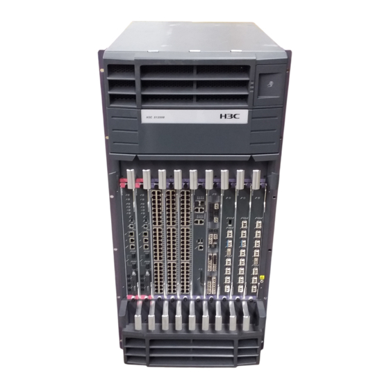
Summary of Contents for H3C S12500

  • Page 1: Table Of Contents

    Contents Installing the switch ······················································································································································ 1   Confirming installation preparations ······························································································································· 2   Installing an impedance carrier (optional) ····················································································································· 2   Installing a chassis air filter (optional) ···························································································································· 3   Installing an expansion cable management bracket (optional) ··················································································· 4   Installation preparation ············································································································································...
  • Page 2: Installing The Switch

    Installing the switch WARNING! To avoid bodily injury, do not touch any wire, terminal, or part marked with a high-voltage hazard sign. Figure 1 Hardware installation flow NOTE: For the S12504, the impedance carrier, expansion cable management bracket, and chassis air filter are not installed.
  • Page 3: Confirming Installation Preparations

    Confirming installation preparations Before installing an H3C S12500 switch, verify that: You have read "Preparing for installation" carefully and the installation site meets all the • requirements. You have all the items listed in the packing list, and the switch was not damaged during shipment.
  • Page 4: Installing A Chassis Air Filter (Optional)

    Chassis air filters are installed at the air intake vents to prevent dust from entering the chassis. Chassis air filters of the S12500 switches are optional. You can order them as needed. If you have ordered chassis air filters, H3C recommends you to install the air filters before mounting the switch to the rack.
  • Page 5: Installing An Expansion Cable Management Bracket (Optional)

    Figure 4 Installing the rear air filter   (1) Ventilation panel (2) Rear air filter Installing an air filter on an S12518 Use a Phillips screwdriver to loosen the screws at both sides of the plastic panel and remove the panel.
  • Page 6: Installation Procedure

    Keep the removed chassis panel and cable management brackets for future use. • Installation procedure Each S12500 switch has keyhole standoffs on its cable management bracket and keyholes on the chassis for attaching the cable management bracket to the chassis. See Figure...
  • Page 7 Figure 7 Installing an upper expansion cable management bracket...
  • Page 8: Installing The Switch In A Rack

    To ensure correct installation, use industry-standard slide rails or rack shelves. Slide rails or rack shelves are not provided with the switch. Prepare them yourself, or order them from H3C. Installing slide rails Before installing the switch to the rack, install slide rails to the rack. If the rack has slide rails, skip this section.
  • Page 9 Make sure the clearance above the slide rail is sufficient for the switch. For the dimensions of the S12500 switch, see "Appendix A Technical specifications." Align the screw holes on the two sides of the slide rail with the corresponding mounting holes on the right rack posts, and then fasten the screws.
  • Page 10: Installing The Mounting Brackets

    Figure 9 Installing the cage nuts Installing the mounting brackets Attach the mounting brackets onto the left and right sides of the switch. Figure 10 Installing the mounting brackets (for the S12504)
  • Page 11: Mounting The Switch In The Rack

    Figure 11 Installing the mounting brackets (for the S12508 and S12518) Mounting the switch in the rack Before you mount the switch in the rack, make sure you have installed slide rails or a rack shelf on the rack for supporting the switch. To maximize the stability of the rack, mount the heaviest switch at the bottom of the rack when you install multiple switches on the rack.
  • Page 12: Verifying The Installation

    Figure 12 Installing the switch in a standard 19-inch rack NOTE: If the screw holes on the mounting brackets cannot align with the cage nuts on the rack, verify that the bottom edge of the slide rail aligns with the middle of the narrowest metal area between mounting holes and that the cage nuts are installed in the correct holes.
  • Page 13: Installation Preparation

    Installation preparation Before placing the switch on a workbench or on the floor, confirm the following preparations: The workbench or floor is sturdy enough to support the weight of the chassis and its accessories. • The workbench or floor is reliably grounded. •...
  • Page 14 Figure 13 Installing the mounting brackets (1) Mounting bracket installation holes (2) Mounting bracket Attach the switch to the workbench or ground with L-shaped brackets. See Figure Figure 14 Installing L-shaped brackets (1) L-shaped bracket (2) Wall anchor (3) Mounting screw...
  • Page 15: Grounding The Switch

    Grounding the switch WARNING! For the safety of operators and equipment, securely ground the switch. Make sure the resistance reading between the switch chassis and the ground is less than 1 ohm. Most racks are equipped with a grounding strip. You can connect the yellow-green grounding cable of the switch to the grounding strip.
  • Page 16: Installing A Power Supply

    If there is no grounding point on the rack, you can attach the grounding cable to a grounding strip. The installation procedures are similar. Installing a power supply The S12500 switches supports both AC and DC power supply. You can select either AC or DC power supplies as needed. For how to connect power cords, see "Connecting power cords."...
  • Page 17: Installing A Dc Power Supply

    To prepare for installation: Wear an ESD-preventive wrist strap and make sure it is properly grounded. Remove the blank panel (if any) from the slot to be used. Remove the power frame cover. Installing a DC power supply Rotate the power frame cover up with both hands. Pull the clip at the bottom left corner of the power supply to the left to open the power supply panel.
  • Page 18 Installing a PEM • • Installing an AC power supply Installing a PEM Loosen the screws on the filler panel of the PEM slot with a Phillips screwdriver to remove the filler panel. Insert a PEM slowly along the slide rails until it touches the backplane connector. Use the M3 screws supplied with the PEM to attach the PEM to the switch chassis, and fasten the screws with a Phillips screwdriver.
  • Page 19: Installing A Fan Tray

    Installing a fan tray CAUTION: The fan trays are heavy. Do not try to move a fan tray by yourself. • Hold a fan tray by the bottom when moving it. Never attempt to lift a fan tray with its handle because the •...
  • Page 20: Installing A Card

    On an S12504, install at least one MPU, one LPU, and three switching fabric modules. On an S12508 or S12518, install at least one MPU, one LPU, and seven switching fabric modules. The S12500 does not support intermixing of the MPU, LPU, and switching fabric modules. Use one of the following positions to install the card: •...
  • Page 21: Installation Preparation

    Unpack the card to be installed. NOTE: Keep the removed the blank panel and protective box properly for future use. • • All the cards for the S12500 are hot-swappable. Installation procedure IMPORTANT: Fasten the screws of each card right after you insert it. •...
  • Page 22 Figure 21 Removing the protective box   Move the ejector levers on the front panel of the MPU outwards, hold up the MPU by one hand without touching any electronic components on the MPU, and hold the front panel by the other hand to push the MPU into the slot along the slide rails slowly.
  • Page 23: Connecting Power Cords

    CAUTION: Typically 10 A busbars are available in the equipment room but the PEM on the S12500 (LSTM2PEMC6) requires a 16 A power cord (AC), so you need to use a 16 A busbar, and make sure the AC power supply system can provide enough power.
  • Page 24: Connecting A Dc Power Cord

    Six pairs of wiring terminals (marked PSR1 through PSR6) are available on the DC grounding strip of the S12500 switches. The wiring terminals correspond to the power supplies 1 through 6, respectively. The power source supplies power to the switch through the wiring terminals. If slot 1 is installed with a power supply, the wiring terminals marked PSR1 must be connected to the power source with a DC power cord to make the power supply operate properly.
  • Page 25 Loosen the fastening screw on the wiring terminal marked with RTN(+) with an M6 wrench, and remove the screw, spring washer, and flat washer. Connect one end of the black DC power cord marked with "–" to the RTN(+) terminal on the power supply, install the flat washer, spring washer, and fasten the screw.
  • Page 26: Verifying The Installation

    Figure 26 Installing the protection cover Verifying the installation WARNING! An S12504 has one power switch, an S12508 has one power switch, and an S12518 has two power switches. Make sure you have turned off the power before checking the installation to avoid bodily injury and switch damage.

This manual is also suitable for:

S12504S12508S12518

Table of Contents