Table of Contents
Advertisement
Quick Links
Download this manual
See also:
User Manual
Advertisement
Table of Contents

Related Manuals for Avalue Technology EMX-PNV


Summary of Contents for Avalue Technology EMX-PNV
-
Page 1: Quick Installation Guide
EMX-PNV Intel® Atom™ PNV-M/ PNV-D Mini ITX Motherboard with Intel® ICH8-M Chipset Quick Installation Guide Ed – September 1 2010 Part No. E2017XPNV00R... - Page 2 Avalue has come to be known. Your satisfaction is our primary concern. Here is a guide to Avalue’s customer services. To ensure you get the full benefit of our services, please follow the instructions below carefully.
- Page 3 Our dealers are well trained and ready to give you the support you need to get the most from your Avalue’s products. In fact, most problems reported are minor and are able to be easily solved over the phone.
-
Page 4: Getting Started
1.2 Packing List Before you begin installing your single board, please make sure that the following materials have been shipped: 1 x EMX-PNV Mini ITX Main Board 1 x DVD-ROM contains the followings: ⎯ User’s manual in pdf file ⎯ Driver 2 x SATA &... - Page 5 EMX-PNV Quick Installation Guide 2. Hardware Configuration EMX-PNV Quick Installation Guide 5...
-
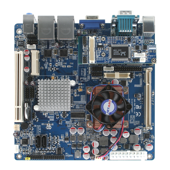
Page 6: Product Overview
EMX-PNV Quick Installation Guide 2.1 Product Overview 6 EMX-PNV Quick Installation Guide... -
Page 7: Jumper And Connector List
Serial port 2 pin 9 signal select – Ring, 3 x 2 header, pitch 2.0 mm +5V, +12V power select Serial port 1 pin 9 signal select – Ring, 3 x 2 header, pitch 2.0 mm +5V, +12V power select EMX-PNV Quick Installation Guide 7... - Page 8 Touch panel connector 5 x 2 header, pitch 2.54 mm TOUCH1 4W/ 5W/ 8W power mode select DIP-SW, 6P TSW1 VGA connector D-sub 15-pin, female VGA1 LCD backlight brightness adjustment 3 x 1 header, pitch 2.54mm 8 EMX-PNV Quick Installation Guide...
-
Page 9: Setting Jumpers & Connectors
2.3 Setting Jumpers & Connectors 2.3.1 Clear CMOS (JBAT1) Protect* Clear CMOS * Default 2.3.2 Miscellaneous setting connector (JFTP1) Signal PIN PIN Signal SB_LED+ AUX TIN +3.3V BUZZER HDD_LED * Default PWR_LED+ RESET Open: AT PWRBTN Short: ATX EMX-PNV Quick Installation Guide 9... - Page 10 EMX-PNV Quick Installation Guide 2.3.3 Serial port 3/ 4/ 2/ 1 pin 9 signal select (JP1/ JP2/ JP3/ JP4) JP2/ 3/ 4 Ring* Ring* +12V +12V * Default 2.3.4 Speaker out connector (CN1) Signal AMP_OUT_LP AMP_OUT_LN AMP_OUT_RN AMP_OUT_RP 10 EMX-PNV Quick Installation Guide...
- Page 11 EMX-PNV Quick Installation Guide 2.3.5 USB connector 4 & 5/ 6 & 7 (CN2/ CN3) Signal PIN PIN Signal P4-/P6- P4+/P6+ P5+/P7+ P5-/P7- 2.3.6 SPI connector (CN4) Signal PIN PIN Signal +3.3V SPI_CS0# SPI_CLK SPI_SO SPI_SI EMX-PNV Quick Installation Guide 11...
- Page 12 EMX-PNV Quick Installation Guide 2.3.7 Serial port 4/ 3 connector (CN5/ CN7) Signal PIN PIN Signal 2.3.8 LCD backlight brightness adjustment (VR1) Signal BRIGHT Variation Resistor (Recommended: 4.7KΩ, >1/16W) 12 EMX-PNV Quick Installation Guide...
- Page 13 VR signal controlled by VR1. Please see the VR1 section for detailed circuitry information. 2.3.9.1 Signal Description – LCD Inverter Connector (CN6) Signal Signal Description BRIGHT Vadj = 0.75V ~ 4.25V (Recommended: 4.7KΩ, >1/16W) LBKLT_EN LCD backlight ON/OFF control signal EMX-PNV Quick Installation Guide 13...
- Page 14 EMX-PNV Quick Installation Guide 2.3.10 CD-ROM Audio Connector (CN8) Signal 2.3.11 Front audio connector (CN9) Signal PIN PIN Signal MIC2_L MIC2_R +3.3V LINE2_R MIC2_JD SENSE_B LINE2_L LINE2_JD 14 EMX-PNV Quick Installation Guide...
- Page 15 EMX-PNV Quick Installation Guide 2.3.12 General purpose I/O connector (DIO1) Signal Signal SMB_CLK SMB_DAT EMX-PNV Quick Installation Guide 15...
- Page 16 EMX-PNV Quick Installation Guide 2.3.13 CPU fan connector (CPU_FAN) FAN2 FAN1 Signal +12V FAN_TAC1 2.3.14 VGA power connector (JVGA1) Signal Signal +12V +12V +12V +12V +3.3V +3.3V 16 EMX-PNV Quick Installation Guide...
- Page 17 EMX-PNV Quick Installation Guide 2.3.15 VGA connector (JVGA2) Signal Signal 2.3.16 Print port connector (LPT1) Signal Signal P_-STB P_AFD# P_ERR# P_INIT# P_SLIN# P_ACK# P_BUSY P_PE P_SLCT EMX-PNV Quick Installation Guide 17...
- Page 18 EMX-PNV Quick Installation Guide 2.3.17 LVDS connector (LVDS1) Signal Signal LVDSA_CLK- LVDSA_CLK+ LVDSA_D2- LVDSA_D2+ LVDSA_D1- LVDSA_D0- LVDSA_D1+ LVDSA_D0+ LCDSA_DDC_SC LCDSA_DDC_SD +3.3V +3.3V 18 EMX-PNV Quick Installation Guide...
- Page 19 EMX-PNV Quick Installation Guide 2.3.18 ATX power connector (PWR1) Signal Signal +3.3V +3.3V -12V +3.3V PS_ON# +12V 2.3.19 4W/ 5W/ 8W power mode select (JSW1) TSW1 4-WIRE 5-WIRE 8-WIRE EMX-PNV Quick Installation Guide 19...
- Page 20 EMX-PNV Quick Installation Guide 2.3.20 Touch panel connector (TOUCH1) Signal Signal PROBE Touch1 4-WIRE 5-WIRE 8-WIRE Right Excite Right Right Sense Bottom Excite Bottom Bottom Sense Sense Left Excite Left Left Sense Top Excite Top Sense 20 EMX-PNV Quick Installation Guide...
Need help?
Do you have a question about the EMX-PNV and is the answer not in the manual?
Questions and answers