
Related Manuals for Avalue Technology EMX-BSWB


Summary of Contents for Avalue Technology EMX-BSWB
- Page 1 EMX-BSWB Intel® Celeron® Processor N3160 Thin Mini ITX Motherboard User’s Manual Ed – 26 April 2019 Part No. E2047EMWB01R...
- Page 2 Disclaimer Avalue Technology Inc. reserves the right to make changes, without notice, to any product, including circuits and/or software described or contained in this manual in order to improve design and/or performance. Avalue Technology assumes no responsibility or liability for the...
-
Page 3: Technical Support
Applications that are described in this manual are for illustration purposes only. Avalue Technology Inc. makes no representation or warranty that such application will be suitable for the specified use without further testing or modification. -
Page 4: Product Warranty
A product returned without proof of the purchase date is not eligible for warranty service. Write the RMA number visibly on the outside of the package and ship it prepaid to your dealer. 4 EMX-BSWB User’s Manual... -
Page 5: Table Of Contents
CPU fan connector (CPU_FAN) ....................28 2.3.19 System fan connector (SYS_FAN) .................... 28 2.3.20 VGA port connector (VGA_CON1) .................... 29 3.BIOS Setup ........................30 Introduction ......................31 Starting Setup ......................31 Using Setup ......................32 Getting Help ......................33 EMX-BSWB User’s Manual... - Page 6 Discard Changes and Reset ....................55 3.6.6.3 Restore Defaults ........................55 3.6.6.4 Launch EFI Shell from filesystem device ................55 4. Drivers Installation....................... 56 Install Chipset Driver ....................57 Install VGA Driver ....................58 Install TXE Driver ....................59 6 EMX-BSWB User’s Manual...
-
Page 7: Emx-Bswb User's Manual
User’s Manual Install Audio Driver (For Realtek ALC662 HD Audio) ..........60 Install LAN Driver (For Realtek RTL8111F) ............61 5. Mechanical Drawing ....................62 EMX-BSWB User’s Manual... -
Page 8: Getting Started
1.2 Packing List Before you begin installing your single board, please make sure that the following materials have been shipped: 1 x EMX-BSWB motherboard 2 x SATA cables 1 x I/O Shield ... -
Page 9: Document Amendment History
User’s Manual 1.3 Document Amendment History Revision Date Comment January 2017 Avalue Initial Release April 2019 Avalue Update Jumper and Connector List EMX-BSWB User’s Manual... -
Page 10: Manual Objectives
We strongly recommend that you study this manual carefully before attempting to set up EMX-BSWB or change the standard configurations. Whilst all the necessary information is available in this manual we would recommend that unless you are confident, you contact your supplier for guidance. -
Page 11: System Specifications
- 1 x full size Mini PCI-e support mSATA and Mini PCI-e only External I/O - 1 x half size Mini PCI-e support WiFi Module Connector - 1 x 3 x 4 pin pitch 2.54mm connector for SATA/ mSATA solution (SATA III and mSATA Switchable Through jumper) EMX-BSWB User’s Manual 11... - Page 12 Connector 1 x Mic-In and 1 x Line-out 1 x DC Jack connector type S/ PDIF Mechanical & Environmental Power DC in +12V Requirement Single power ATX Support S0, S3, S4, S5 ACPI ACPI 3.0 Compliant 12 EMX-BSWB User’s Manual...
- Page 13 0%~90% relative humidity, non-condensing Humidity Size (L x W) 6.7" x 6.7" (170mm x 170mm) Weight 0.40 kg MS Win 7,Win 8.1,Win 10 OS Support (listed in accordance with Intel document) Note: Specifications are subject to change without notice. EMX-BSWB User’s Manual 13...
-
Page 14: Architecture Overview-Block Diagram
EMX-BSWB User’s Manual 1.6 Architecture Overview—Block Diagram The following block diagram shows the architecture and main components of EMX-BSWB. 14 EMX-BSWB User’s Manual... -
Page 15: Hardware Configuration
User’s Manual 2. Hardware Configuration EMX-BSWB User’s Manual 15... -
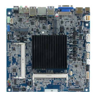
Page 16: Product Overview
EMX-BSWB User’s Manual 2.1 Product Overview 16 EMX-BSWB User’s Manual... -
Page 17: Jumper And Connector List
4 x 1 wafer, pitch 2.54mm CPU_FAN System fan connector 3 x 1 wafer, pitch 2.54mm SYS_FAN Flash BIOS ME connector 1 x 2 header, pitch 2.54mm ME_PROTECT INVERTER1 Inverter connector 1 x 6 wafer, pitch 2.00mm EMX-BSWB User’s Manual 17... - Page 18 HDD_PWR1 HDD_PWR2 SATA Power connector 2 4 x 1 wafer, pitch 2.00mm HDMI1 HDMI connector B_OUT1 Line-out audio jack B_MIC1 Mic-in audio jack VGA1 VGA connector VGA_CON1 VGA port connector 1 x 12 header, pitch 2.00mm 18 EMX-BSWB User’s Manual...
-
Page 19: Setting Jumpers & Connectors
(SATA1 Connector enabled, MSATA1 slot Disabled) MSATA1 mPCIe slot (MSATA1 slot enabled, SATA1 Connector (Disabled) * Default Note: SATA1/MSATA1 shared SATA signal can not be used simultaneously. 2.3.2 LCD power voltage setting (LCD_VOL_SEL2) +5V* +3.3V +12V * Default EMX-BSWB User’s Manual 19... -
Page 20: Lvds 6/8Bit And Dual Or Single Lvds Selection (Jlvds1)
Pin 1 & 3 & 5 for 6bit or 8bit VESA or JEIDA selection. Pin 2 & 4 & 6 for dual or single channel LVDS selection. Pin 2 & 4 NC for dual channel LVDS Pin 2 & 4 Close for single channel LVDS 20 EMX-BSWB User’s Manual... -
Page 21: Clear Cmos (Clr_Cmos)
User’s Manual 2.3.4 Clear CMOS (CLR_CMOS) Protect* Clear CMOS * Default 2.3.5 Flash BIOS ME connector (ME_PROTECT) Protect* Flash BISO ME EMX-BSWB User’s Manual 21... -
Page 22: Inverter Connector (Inverter1)
EMX-BSWB User’s Manual 2.3.6 Inverter connector (INVERTER1) Signal +12V +12V BLK_ON Brightness 2.3.7 Serial port 1 connector (COM_A) Signal PIN PIN Signal NRI# NCTS# NRTS# NDSR# NDTR# NTXD Note: NRXD NDCD# Pin 9 without Power. 22 EMX-BSWB User’s Manual... -
Page 23: Sata Power Connector 1 (Hdd_Pwr1)
User’s Manual 2.3.8 SATA Power connector 1 (HDD_PWR1) Signal +V5S_SATA +V12S_SATA 2.3.9 SATA Power connector 2 (HDD_PWR2) Signal +V5S_SATA +V12S_SATA EMX-BSWB User’s Manual 23... -
Page 24: Power Input Connector (Jdcin1)
EMX-BSWB User’s Manual 2.3.10 Power input connector (JDCIN1) Signal Signal +VIN_12V +VIN_12V 2.3.11 Battery connector (BAT1) Signal 24 EMX-BSWB User’s Manual... -
Page 25: Usb 2.0 Connector (Fusb20_1)
User’s Manual 2.3.12 USB 2.0 connector (FUSB20_1) Signal +V5A_USB USB_DN4 USB_DP4 2.3.13 USB 2.0 connector (FUSB20_2) Signal Signal +V5A_USB +V5A_USB USB_DN3 USB_DN4 USB_DP3 USB_DP4 EMX-BSWB User’s Manual 25... -
Page 26: Front Audio Connector (F_Audio1)
18 LVDSA_DATA3P LVDSB_TX0N LVDSB_TX0P LVDSB_TX1N LVDSB_TX1P LVDSB_TX2N LVDSB_TX2P Note: LVDSB_CLKN LVDSB_CLKP 1. Mapping connector 1 x 2 x 15 pin, pitch 2.0mm LVDSB_TX3N LVDSB_TX3P connector. 2. The VCC voltage can be change by JPWR_LVDS1 jumper. (Page.20). 26 EMX-BSWB User’s Manual... -
Page 27: Speaker Connector (Speakers1)
User’s Manual 2.3.16 Speaker connector (SPEAKERS1) Signal LSPK+ LSPK- RSPK+ RSPK- 2.3.17 Front Panel connector (F_PANEL) Signal PIN PIN Signal +HD_LED +PWR_LED -HD_LED -PWE_LED +Reset +PWR_BNT -Reset -PWR_BNT EMX-BSWB User’s Manual 27... -
Page 28: Cpu Fan Connector (Cpu_Fan)
EMX-BSWB User’s Manual 2.3.18 CPU fan connector (CPU_FAN) Signal +12V CPU_FANIN CPU_FANOUT 2.3.19 System fan connector (SYS_FAN) Signal +12V SYS_FANIN 28 EMX-BSWB User’s Manual... -
Page 29: Vga Port Connector (Vga_Con1)
User’s Manual 2.3.20 VGA port connector (VGA_CON1) Signal 5V_DDCA_CLK 5V_DDCA_DAT VGA_B VGA_G VGA_R 5V-HSYNC_R 5V_VSYBC_R EMX-BSWB User’s Manual 29... -
Page 30: Bios Setup
EMX-BSWB User’s Manual 3.BIOS Setup 30 EMX-BSWB User’s Manual... -
Page 31: Introduction
If you do not press the keys at the correct time and the system does not boot, an error message will be displayed and you will again be asked to. Press F1 to Continue, DEL to enter SETUP EMX-BSWB User’s Manual 31... -
Page 32: Using Setup
Note: Some of the navigation keys differ from one screen to another. To Display a Sub Menu Use the arrow keys to move the cursor to the sub menu you want. Then press <Enter>. A “” pointer marks all sub menus. 32 EMX-BSWB User’s Manual... -
Page 33: Getting Help
BIOS Vendor and your systems manufacturer to provide the absolute maximum performance and reliability. Even a seemingly small change to the chipset setup has the potential for causing you to use the override. EMX-BSWB User’s Manual 33... -
Page 34: Bios Setup
<Enter> to accept and enter the sub-menu. 3.6.1 Main Menu This section allows you to record some basic hardware configurations in your computer and set the system clock. 34 EMX-BSWB User’s Manual... -
Page 35: System Language
Visit the Avalue website (www.avalue.com.tw) to download the latest product and BIOS information. 3.6.2 Advanced Menu This section allows you to configure your CPU and other system devices for basic operation through the following sub-menus. EMX-BSWB User’s Manual 35... -
Page 36: Apci Settings
SUSPEDN S3 (Suspend to RAM)[Default] button is pressed. Off[Default] PWR-On After PWR-Fail AC loss resume. Last state Disabled[Default], 30 sec 40 sec 50 sec Watch Dog Select WatchDog. 1 min 2 min 10 min 30 min 36 EMX-BSWB User’s Manual... -
Page 37: Nct5567D-B Super Io Configuration
User’s Manual 3.6.2.2 NCT5567D-B Super IO Configuration Item Description Serial Port 1 Configuration Set Parameters of Serial Port 1 (COMA). 3.6.2.3 Hardware Monitor Item Options Description Disabled CPUFan Smart Fan Function Enable/Disable CPUFan Smart Fan Function. Enabled[Default] EMX-BSWB User’s Manual 37... -
Page 38: S5 Rtc Wake Settings
Enable or disable System wake on alarm event. Disabled[Default], Select Fixed Time, system will wake on the Wake system from S5 Fixed Time hr::min::sec specified. Select Dynamic Time, Dynamic Time System will wake on the current time + Increase minute(s). 38 EMX-BSWB User’s Manual... -
Page 39: Serial Port Console Redirection
User’s Manual 3.6.2.5 Serial Port Console Redirection Item Options Description Disabled[Default], Console Redirection Console Redirection Enable or Disable. Enabled 3.6.2.6 CPU Configuration Use the CPU configuration menu to view detailed CPU specification and configure the CPU. EMX-BSWB User’s Manual 39... -
Page 40: Socket 0 Cpu Information
Custom[Default] Disabled, EIST Enable/Disable Intel SpeedStep. Enabled[Default] Disabled, Turbo Mode Turbo Mode. Enabled[Default] HW_ALL[Default] P-STATE Coordination SW_ALL Change P-STATE Coordination type. SW_ANY Package C State limit C1[Default]/3/6/7 Package C State limit. 3.6.2.6.1 Socket 0 CPU Information 40 EMX-BSWB User’s Manual... -
Page 41: Cpu Thermal Configuration
User’s Manual 3.6.2.6.2 CPU Thermal Configuration Item Options Description Enabled Enabled/Disable Digital Thermal Sensor. Disabled[Default], 3.6.2.7 SATA Configuration EMX-BSWB User’s Manual 41... -
Page 42: Miscellaneous Configuration
Select SATA Interface Speed, CHV A1 always SATA Interface Speed Gen2 with Gen 1 Speed. Gen3[Default] Disabled, Port1/2 Enable/Disable SATA Port. Enabled[Default] 3.6.2.8 Miscellaneous Configuration Item Options Description WIN 8/WIN 10 BOM Config Legacy System (WIN 7)[Default] BOM Config. Yocto Linux 42 EMX-BSWB User’s Manual... -
Page 43: Network Stack Configuration
User’s Manual 3.6.2.9 Network Stack Configuration Item Options Description Enabled Network Stack Enable/Disable UEFI Network Stack. Disabled[Default] 3.6.2.10 CSM Configuration EMX-BSWB User’s Manual 43... -
Page 44: Usb Configuration
Maximum time the device will take before it properly reports itself to the Host Controller. ‘Auto’ Auto[Default] Device power-up delay Manual uses default value: for a Root port it is 100ms, for a Hub port the delay is taken form Hub descriptor. 44 EMX-BSWB User’s Manual... -
Page 45: Chipset
Optical drives are emulated as ‘CDROM’, Mass Storage Devices Forced FDD Hard Disk drives with no media will be emulated according CD-ROM to a drive type. 3.6.3 Chipset 3.6.3.1 North Bridge EMX-BSWB User’s Manual 45... -
Page 46: Intel Igd Configuration
Maximum Value of TOLUD. 2.5 GB 2.75 GB 3.6.3.1.1 Intel IGD Configuration Item Option Description Auto[Default] Select which of IGD/PCI Graphics device Primary Display should be Primary Display. PCIe Enabled, GFX Boost Enable/Disable GFX Boost. Disabled[Default] 46 EMX-BSWB User’s Manual... -
Page 47: South Bridge
User’s Manual 3.6.3.2 South Bridge 3.6.3.2.1 Azalia Configuration Item Option Description Control Detection of the Azalia device. Disabled = Enabled[Default], Audio Controller Azalia will be unconditionally disabled. Enabled = Disabled Azalia will be unconditionally Enabled. EMX-BSWB User’s Manual 47... -
Page 48: Usb Configuration
EMX-BSWB User’s Manual Enabled[Default], Azalia HDMI Codec Port D Enable/Disable HDMI Port codec for Azalia. Disabled 3.6.3.2.2 USB Configuration Item Option Description Enabled[Default], XHCI Mode Mode of operation of xHCI controller. Disabled 48 EMX-BSWB User’s Manual... -
Page 49: Pci Express Configuration
User’s Manual 3.6.3.2.3 PCI Express Configuration 3.6.3.2.3.1 PCIE Express Root Port2 EMX-BSWB User’s Manual 49... - Page 50 PCI Express Root Port 2/3 Control the PCI Express Root Port. Disabled Auto Disabled[Default] PCI Express Active State Power ASPM Management settings. L0sL1 Auto[Default] Configure PCIe Speed. CHV A1 always with PCIe Speed Gen 2 Gen 1 Speed. Gen 1 50 EMX-BSWB User’s Manual...
-
Page 51: Security
User’s Manual 3.6.4 Security Administrator Password Set setup Administrator Password User Password Set User Password EMX-BSWB User’s Manual 51... -
Page 52: Secure Boot Menu
Secure Boot User mode with enrolled Platform Key(PK) 2.CSM Enabled function is disabled. Secure Boot mode selector. ‘Custom’ Mode enables Standard Secure Boot Mode users to change Image Execution policy and manage Custom[Default] Secure Boot Keys. 52 EMX-BSWB User’s Manual... -
Page 53: Key Management
User’s Manual 3.6.4.1.1 Key Management Item Option Description Enabled, Install Factory default Secure Boot Keys Provision Factory Default Keys Disabled[Default] when System is in Setup Mode. 3.6.5 Boot EMX-BSWB User’s Manual 53... -
Page 54: Save And Exit
65535(0xFFFF) means indefinite waiting. On[Default] Bootup NumLock State Select the Keyboard NumLock state Disabled[Default] Quiet Boot Enables or disables Quiet Boot option Enabled Boot Option #1 Set the system boot order. 3.6.6 Save and exit 54 EMX-BSWB User’s Manual... -
Page 55: Save Changes And Reset
Reset system setup without saving any changes. 3.6.6.3 Restore Defaults Restore/Load Default values for all the setup options. 3.6.6.4 Launch EFI Shell from filesystem device Attempts to Launch EFI Shell application (Shell.efi) from one of the available filesystem devices. EMX-BSWB User’s Manual 55... -
Page 56: Drivers Installation
EMX-BSWB User’s Manual 4. Drivers Installation Note: Installation procedures and screen shots in this section are for your reference and may not be exactly the same as shown on your screen. 56 EMX-BSWB User’s Manual... -
Page 57: Install Chipset Driver
Windows 10 operation system. If the warning message appears while the installation process, click Continue to go on. Step 3. Click Install. Step 4. Click Finish to complete setup. Step1. Click Next. Step 2. Click Accept. EMX-BSWB User’s Manual 57... -
Page 58: Install Vga Driver
Windows 10 operation system. Step 3. Click Next. Step 1. Click Next to continue installation. Step 4. Click Next. Step 2. Step 5. Click Finish to complete setup. Click Yes to accept license agreement. 58 EMX-BSWB User’s Manual... -
Page 59: Install Txe Driver
Note: The installation procedures and screen shots in this section are based on Windows 10 operation system. Step 3. Click Next Step 4. Click Finish to complete the setup Step 1. Click Next to continue setup. Step 2. Click Next. EMX-BSWB User’s Manual 59... -
Page 60: Install Audio Driver (For Realtek Alc662 Hd Audio)
Windows 10 operation system. If the warning message appears while the installation process, click Continue to go on. Step1. Click Next to Install. Step 2. Select Finish to complete Installation. 60 EMX-BSWB User’s Manual... -
Page 61: Install Lan Driver (For Realtek Rtl8111F)
Note: The installation procedures and screen shots in this section are based on Windows 10 operation system. Step 3. Click Finish to complete setup. Step 1. Click Next to continue installation. Step 2. Click Install. EMX-BSWB User’s Manual 61... -
Page 62: Mechanical Drawing
EMX-BSWB User’s Manual 5. Mechanical Drawing 62 EMX-BSWB User’s Manual... - Page 63 User’s Manual Unit: mm EMX-BSWB User’s Manual 63...
- Page 64 EMX-BSWB User’s Manual Unit: mm 64 EMX-BSWB User’s Manual...
Need help?
Do you have a question about the EMX-BSWB and is the answer not in the manual?
Questions and answers