
Related Manuals for Avalue Technology EMX-CDV


Summary of Contents for Avalue Technology EMX-CDV
- Page 1 EMX-CDV Intel® Atom™ EMX-CDV Mini ITX Motherboard with Intel® ICH10R Chipset User’s Manual Ed – 17 Septemper 2012 Part No. E2047XCDV00R...
- Page 2 Disclaimer Avalue Technology Inc. reserves the right to make changes, without notice, to any product, including circuits and/or software described or contained in this manual in order to improve design and/or performance. Avalue Technology assumes no responsibility or liability for the...
-
Page 3: Technical Support
Avalue has come to be known. Your satisfaction is our primary concern. Here is a guide to Avalue’s customer services. To ensure you get the full benefit of our services, please follow the instructions below carefully. - Page 4 Our dealers are well trained and ready to give you the support you need to get the most from your Avalue’s products. In fact, most problems reported are minor and are able to be easily solved over the phone.
-
Page 5: Product Warranty
If any of Avalue’s products is defective, it will be repaired or replaced at no charge during the warranty period. For out-of-warranty repairs, you will be billed according to the cost of replacement materials, service time, and freight. -
Page 6: Table Of Contents
SATA Power (SATAPW_1) ......................32 2.4.17 SATA Power (SATAPW_2) ......................33 2.4.18 USB Connector (F_USB1) ......................33 2.4.19 USB Connector (F_USB2) ......................34 2.4.20 GPIO Connector (GPIO_CNT) ....................34 2.4.21 Low Pin Count Connector (LPC) ....................35 6 EMX-CDV User’s Manual... - Page 7 Save & Exit ............................. 58 3.6.6.1 Save Changes and Exit ......................58 3.6.6.2 Discard Changes and Exit ..................... 59 3.6.6.3 Save Changes and Reset ...................... 59 3.6.6.4 Discard Changes and Reset ....................59 3.6.6.5 Save Changes ........................59 EMX-CDV User’s Manual 7...
- Page 8 EMX-CDV 3.6.6.6 Discard Changes ........................59 3.6.6.7 Restore Defaults ........................59 3.6.6.8 Save as user defaults ......................59 3.6.6.9 Restore user defaults ......................59 3.6.6.10 Boot override ......................... 59 4. Mechanical Drawing ....................61 8 EMX-CDV User’s Manual...
-
Page 9: Getting Started
1.2 Packing List Before you begin installing your single board, please make sure that the following materials have been shipped: 1 x EMX-CDV Mini-ITX Motherboard 1 x CD-ROM contains OS drivers/QIG/User’s Manual 1 x COM cable ... -
Page 10: Document Amendment History
EMX-CDV 1.3 Document Amendment History Revision Date Comment June 2012 Initial Release 10 EMX-CDV User’s Manual... - Page 11 We strongly recommend that you study this manual carefully before attempting to interface with EMX-CDV series or change the standard configurations. Whilst all the necessary information is available in this manual we would recommend that unless you are confident, you contact your supplier for guidance.
-
Page 12: System Specifications
2 External(COM1, RS-232/422/485; COM2, RS-232), 4 Internal (COM3, RS-232 with 5V/12V selected by jumper, COM4~6, RS-232), 4 SATA II, 1 HDMI, 1 VGA, 1 LVDS, 2 LAN, 1 PS/2 7 USB 2.0 (4 Rear, 3 Internal) 12 EMX-CDV User’s Manual... - Page 13 ATX 12V Power Connector Mechanical & Environmental Operating Temperature 0°C to 60°C (32°F to 140°F) Operating Humidity 0% to 90% relative humidity, non-condensing Size 6.69" x 6.69" (170 x 170 mm) 0.77 Ibs (0.35 Kg) Weight EMX-CDV User’s Manual 13...
-
Page 14: Architecture Overview - Block Diagram
EMX-CDV 1.5 Architecture Overview – Block Diagram The following block diagram shows the architecture and main components of EMX-CDV. 14 EMX-CDV User’s Manual... -
Page 15: Hardware Configuration
User’s Manual 2. Hardware Configuration EMX-CDV User’s Manual 15... -
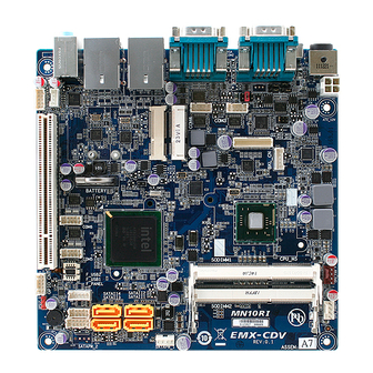
Page 16: Product Overview
Overview 2.1 Product Overview EMX-CDV is designed to unleash the power of the new Intel® Atom™ processor D2000 / N2000 which supports the new revolutionary two–chip layout. The Intel® Cedarview processor also provides additional flexibility and upgradeability with two slots of single channel DDR3 memory at 1066 MHz supporting up to 4GB maximum. - Page 17 User’s Manual • Main Memory EMX-CDV provides 2x 204-pin DDR3 SODIMM, up to 4GB (N2600 support 1 x DDR3 SODIMM only). SODIMM module. Note: (1) Please do not change any DDR SDRAM parameter in BIOS setup to increase your system’s performance without acquiring technical information in advance.
-
Page 18: Before You Proceed
Before you install or remove any component, ensure that the ATX power supply is switched off or the power cord is detached from the power supply. Failure to do so may cause severe damage to the motherboard, peripherals, and/or components. 18 EMX-CDV User’s Manual... -
Page 19: Motherboard Overview
Place four (4) screws into the holes indicated by circles to secure the motherboard to the chassis. Place this side towards the rear of the chassis. Do not over tighten the screws! Doing so can damage the motherboard. EMX-CDV User’s Manual 19... - Page 20 EMX-CDV 20 EMX-CDV User’s Manual...
- Page 21 Power Mode Select – AT or ATX AT_CN 3 x 1 header, pitch 2.00 mm CLR_CMOS Clear CMOS 2 x 1 header, pitch 2.54 mm Connectors Label Function Note ATX_12V ATX 4pin DC12 SODIMM1 DIMM Slot DDR3 EMX-CDV User’s Manual 21...
- Page 22 GPIO_CNT GPIO Connector 6 x 2 wafer, pitch 2.00 mm Low Pin Count Connector 7 x 2 wafer, pitch 2.00 mm F_PANEL Front Panel Connector 6 x 2 wafer, pitch 2.00 mm DC_IN DC Power-In Connector 22 EMX-CDV User’s Manual...
-
Page 23: Setting Jumpers & Connectors
2.4 Setting Jumpers & Connectors 2.4.1 Serial Port 1 Setting - RS232/422/485 (JRS1, JRS2, JRS3, JRS4) RS232 JRS3 JRS1 JRS2 JRS4 RS422/RS485 RS422/485 Pin Mapping * Default RS-232 RS-485 RS-422 TXD- TXD- TXD+ TXD+ RXD+ RXD- EMX-CDV User’s Manual 23... -
Page 24: Serial Port 1 Select - Rs-232/422/485 (Jcom1)
EMX-CDV 2.4.2 Serial Port 1 Select - RS-232/422/485 (JCOM1) RS232* RS485 RS422 * Default Signal PIN PIN Signal RXD232 RXD1 RXD422 RXD1 RXD485 RXD1 24 EMX-CDV User’s Manual... -
Page 25: Serial Port 3 Ri Pin Signal Select - Ring/+5V/+12V (Jcom3)
User’s Manual 2.4.3 Serial Port 3 RI Pin Signal Select – Ring/+5V/+12V (JCOM3) +12V Ring* * Default Signal PIN PIN Signal RI3-/5V/12V NRI3- RI3-/5V/12V +12V RI3-/5V/12V EMX-CDV User’s Manual 25... -
Page 26: Power Mode Select - At Or Atx (At_Cn)
EMX-CDV Power Mode Select – AT or ATX (AT_CN) 2.4.4 ATX * Signal * Default AT_PWR_F_BTN# PWR_F_BTN# 2.4.5 Clear CMOS (CLR_CMOS) Normal * Clear Signal -RTCRST * Default 26 EMX-CDV User’s Manual... -
Page 27: System Fan Connector (Sys_Fan)
User’s Manual 2.4.6 System Fan Connector (SYS_FAN) Signal PWM Input FANIO2 +12V 2.4.7 Serial Port 3 Connector (COM3) Signal PIN PIN Signal RI3-/5V/12V NCTS3- NRTS3- NDSR3- NDTR3- NTXD3- NRXD3- NDCD3- EMX-CDV User’s Manual 27... -
Page 28: Serial Port 4 Connector (Com4)
2.4.8 Serial Port 4 Connector (COM4) Signal PIN PIN Signal NRI4- NCTS4- NRTS4- NDSR4- NDTR4- NTXD4- NRXD4- NDCD4- 2.4.9 Serial Port 5 Connector (COM5) Signal PIN PIN Signal NRI5- NCTS5- NRTS5- NDSR5- NDTR5- NTXD5- NRXD5- NDCD5- 28 EMX-CDV User’s Manual... -
Page 29: Serial Port 6 Connector (Com6)
NRXD6- NDCD6- 2.4.11 LVDS Connector (LVDS) Signal PIN PIN Signal VCC3 VCC3 SCL1 SDA1 +RXO1_C +RXO0_C -RXO1_C -RXO0_C +RXO3_C +RXO2_C -RXO3_C -RXO2_C +RXE1_C +RXE0_C -RXE1_C -RXE0_C +RXE3_C +RXE2_C -RXE3_C -RXE2_C +RXECLKE_C +RXECLKO_C -RXECLKE_C -RXECLKO_C +12V +12V EMX-CDV User’s Manual 29... -
Page 30: Lcd Inverter Connector (Bkl_Cn)
Signal +12V BKLTEN BKLTCTL 2.4.13 Front Panel Connector (F_PANEL) Signal PIN PIN Signal Standby Standby Power LED+ Power LED- -INTRUDER SATA LED- SATA LED+ Power LED Power LED+ System RST GND Reset# Power Button Power Button# 30 EMX-CDV User’s Manual... -
Page 31: Front Panel Audio Connector (F_Audio)
Active low when an Intel® HD Audio dongle is connected HPOUT_R_H Front panel headphone right channel HPOUT_L_H Front panel headphone left channel SRTN1 Jack detection for front panel microphone SRTN2 Jack detection for front panel headphone FAUDIO_JD Front panel jack detect EMX-CDV User’s Manual 31... -
Page 32: Audio Amplifier Connector (Spk_Out)
EMX-CDV 2.4.15 Audio Amplifier Connector (SPK_OUT) Signal OUT_R+ OUT_R- OUT_L- OUT_L+ 2.4.16 SATA Power (SATAPW_1) Signal +12V 32 EMX-CDV User’s Manual... -
Page 33: Sata Power (Satapw_2)
User’s Manual 2.4.17 SATA Power (SATAPW_2) Signal +12V 2.4.18 USB Connector (F_USB1) Signal PIN PIN Signal USB Power USB Power USBP0- USBP1- USBP0+ USBP1+ EMX-CDV User’s Manual 33... -
Page 34: Usb Connector (F_Usb2)
EMX-CDV 2.4.19 USB Connector (F_USB2) Signal USBP2+ USBP2- USB Power 2.4.20 GPIO Connector (GPIO_CNT) Signal PIN PIN Signal SMBCLK SMBDATA SOGP0_4 SOGP1_4 SOGP0_3 SOGP1_3 SOGP0_2 SOGP1_2 SOGP0_1 SOGP1_1 34 EMX-CDV User’s Manual... -
Page 35: Low Pin Count Connector (Lpc)
User’s Manual 2.4.21 Low Pin Count Connector (LPC) Signal PIN PIN Signal -LDRQ1 5VDUAL SERIRQ LPC_CLK LAD3 -LFRAME LAD2 -PFMRST LAD1 VCC3 LAD0 EMX-CDV User’s Manual 35... -
Page 36: Bios Setup
EMX-CDV 3. BIOS Setup 36 EMX-CDV User’s Manual... -
Page 37: Introduction
If you do not press the keys at the correct time and the system does not boot, an error message will be displayed and you will again be asked to. Press F1 to Continue, DEL to enter SETUP EMX-CDV User’s Manual 37... -
Page 38: Using Setup
Note: Some of the navigation keys differ from one screen to another. To Display a Sub Menu Use the arrow keys to move the cursor to the sub menu you want. Then press <Enter>. A “” pointer marks all sub menus. 38 EMX-CDV User’s Manual... -
Page 39: Getting Help
AMI and your systems manufacturer to provide the absolute maximum performance and reliability. Even a seemingly small change to the chipset setup has the potential for causing you to use the override. EMX-CDV User’s Manual 39... -
Page 40: Bios Setup
Note: BIOS setup screens shown in this chapter are for reference only, and may not exactly match what you see on your screen. Visit the Avalue website (www.avalue.com.tw) to download the latest product and BIOS information. 40 EMX-CDV User’s Manual... -
Page 41: Advanced Bios Settings
Item Options Description In case of multiple Option ROMs (Legacy and Legacy ROM[Default] EFI Compatible), specifies what PCI Option PCI ROM Priority EFI Compatible ROM ROM to launch. 3.6.2.1 PCI Subsystem Settings EMX-CDV User’s Manual 41... -
Page 42: Pci Express Settings
Enables or Disables PCI Express Device No Snoop Disabled No Snoop option. Auto[Default] 128 Bytes Set Maximum Payload of PCI Express 256 Bytes Maximum Payload Device or allow System BIOS to select the 512 Bytes value. 1024 Bytes 2048 Bytes 42 EMX-CDV User’s Manual... -
Page 43: Acpi Settings
Select the highest ACPI sleep state the S1 (CPU Stop Clock), system will enter when the SUSPEND ACPI Sleep State S3 (Suspend to RAM) [Default] button is pressed. Enabled Enable or Disable S3 Video Repost S3 Video Repost Disabled[Default] EMX-CDV User’s Manual 43... -
Page 44: S5 Rtc Wake Settings
When enabled, System will wake on the Disabled[Default] hr::min::sec specified. Enable or disable wake on alarm event. When Enabled Wake system with Dynamic Time enabled, System will wake on the current time Disabled[Default] + Increase minutes (s) 3.6.2.4 Trusted Computing 44 EMX-CDV User’s Manual... -
Page 45: Cpu Configuration
Enabled supporting OS (Windows Server 2003 SPI, Execute Disable Bit Disabled[Default] Windows XP SP2, SuSE Linux 9.2, RedHat Enterprise 3 Update 3. Enabled Limit CPUID Maximum Disabled for Windows XP. Disabled[Default] EMX-CDV User’s Manual 45... -
Page 46: Sata Configuration
Select IDE/ AHCI/ RAID Mode. ACHI Mode RAID Mode Enabled Serial-ATA Controller 0 Disabled Enable/ Disable Serial ATA Controller 0. Compatible[Default] Enabled[Default] Serial-ATA Controller 1 Enable/ Disable Serial ATA Controller 1. Disabled Enabled eSATA Port Support. eSATA Port Support Disabled[Default] 46 EMX-CDV User’s Manual... -
Page 47: Legacy Usb Configuration
Mass storage device emulation type. ‘AUTO’ Floppy enumerates devices less than 530MB as floppies. Forced FDD Generic STORAGE DEVICE 9407 Forced FDD option can be used to force HDD Hard Disk formatted drive to boot as FDD (e.g. ZIP drive). CD-ROM EMX-CDV User’s Manual 47... -
Page 48: F81214 Second Super Io Configuration
You can use this item to set up or change the F81214 Second Super IO configuration for serial ports. Please refer to 3.6.2.8.1 and 3.6.2.8.2 for more information. Item Description Serial Port 1 Configuration Set Parameters of Serial Port 1 (COM1). Serial Port 2 Configuration Set Parameters of Serial Port 2 (COM2). 48 EMX-CDV User’s Manual... -
Page 49: Serial Port 1 Configuration
3.6.2.8.1 Serial Port 1 Configuration Item Option Description Enabled Enable or Disable Serial Port Serial Port Disabled[Default] (COM). 3.6.2.8.2 Serial Port 2 Configuration Item Option Description Enabled Enable or Disable Serial Port Serial Port Disabled[Default] (COM). EMX-CDV User’s Manual 49... -
Page 50: It8783F Super Io Configuration
Set Parameters of Serial Port 3 (COM3). Serial Port 4 Configuration Set Parameters of Serial Port 4 (COM4). Serial Port 5 Configuration Set Parameters of Serial Port 5 (COM5). Serial Port 6 Configuration Set Parameters of Serial Port 6 (COM6). 50 EMX-CDV User’s Manual... -
Page 51: Serial Port 3 Configuration
3.6.2.9.1 Serial Port 3 Configuration Item Option Description Enabled Enable or Disable Serial Port Serial Port Disabled[Default] (COM). 3.6.2.9.2 Serial Port 4 Configuration Item Option Description Enabled Enable or Disable Serial Port Serial Port Disabled[Default] (COM). EMX-CDV User’s Manual 51... -
Page 52: Serial Port 5 Configuration
3.6.2.9.3 Serial Port 5 Configuration Item Option Description Enabled Enable or Disable Serial Port Serial Port Disabled[Default] (COM). 3.6.2.9.4 Serial Port 6 Configuration Item Option Description Enabled Enable or Disable Serial Port Serial Port Disabled[Default] (COM). 52 EMX-CDV User’s Manual... -
Page 53: It8783F H/W Monitor
User’s Manual 3.6.2.10 IT8783F H/W Monitor The H/W Monitor shows the operating temperature, fan speeds and system voltages. 3.6.3 Advanced Chipset Features EMX-CDV User’s Manual 53... - Page 54 Network Devices. Enabled[Default] Enable or Disable the PCI Express Ports in Mini PCIE1 Disabled the Chipset. Enabled[Default] Enable or Disable the PCI Express Ports in Mini PCIE2 Disabled the Chipset. Intel IGD Configuration Config Intel IGD Settings. 54 EMX-CDV User’s Manual...
-
Page 55: Intel Igd Configuration
LVDS Backlight PWM Configuration. 100% 1024x768 1ch 24bit[Default] 800x600 1ch 1024x768 1ch 18bit 1024x600 1ch 1280x800 1ch 1920x1200 2ch 640x480 1ch Panel ID Panel ID. 800x480 1ch 1280x1024 2ch 1440x900 2ch 1600x1200 2ch 1366x768 1ch 1920x1080 2ch 1680x1050 2ch EMX-CDV User’s Manual 55... -
Page 56: Boot Settings
POSTPONED – execute the trap during legacy boot. Enable/Disable CSM Support. If Disabled Auto is selected, based on OS, CSM Support Enabled[Default] CSM will be enabled/disabled Auto automatically. Boot Option #1/2/3 Sets the system boot order 56 EMX-CDV User’s Manual... -
Page 57: Security
If only the User's password is set, then this is a power on password and must be entered to boot or enter the BIOS setup program. In the BIOS setup program, the User will have Administrator rights. By default, no password is specified. EMX-CDV User’s Manual 57... -
Page 58: Save & Exit
EMX-CDV 3.6.6 Save & Exit 3.6.6.1 Save Changes and Exit Use the save changes and reset option to save the changes made to the BIOS options and to exit the BIOS configuration setup program. 58 EMX-CDV User’s Manual... -
Page 59: Discard Changes And Exit
This option restores all BIOS settings to the user defaults. This option is useful for restoring previously preserved custom BIOS setup configurations. 3.6.6.10 Boot override This option lists all possible bootable devices and allows the user to override the Boot EMX-CDV User’s Manual 59... - Page 60 If BIOS setup options have been changed and saved, a reboot will be required and the boot override selection will not be valid. 60 EMX-CDV User’s Manual...
-
Page 61: Mechanical Drawing
User’s Manual 4. Mechanical Drawing EMX-CDV User’s Manual 61... - Page 62 EMX-CDV 62 EMX-CDV User’s Manual...
Need help?
Do you have a question about the EMX-CDV and is the answer not in the manual?
Questions and answers