
Related Manuals for Avalue Technology EMX-SKLUP


Summary of Contents for Avalue Technology EMX-SKLUP
- Page 1 EMX-SKLUP Intel® 6th Generation ULT Processor Thin Mini ITX Motherboard User’s Manual Ed – 30 April 2018 Part No. E2047MSKU02R...
- Page 2 Disclaimer Avalue Technology Inc. reserves the right to make changes, without notice, to any product, including circuits and/or software described or contained in this manual in order to improve design and/or performance. Avalue Technology assumes no responsibility or liability for the...
-
Page 3: Technical Support
Applications that are described in this manual are for illustration purposes only. Avalue Technology Inc. makes no representation or warranty that such application will be suitable for the specified use without further testing or modification. -
Page 4: Product Warranty
A product returned without proof of the purchase date is not eligible for warranty service. Write the RMA number visibly on the outside of the package and ship it prepaid to your dealer. 4 EMX-SKLUP User’s Manual... -
Page 5: Table Of Contents
Miscellaneous setting connector 1 (FPT1) ................32 2.3.21 Miscellaneous setting connector 2 (FPT2) ................32 2.3.22 LED indicator connector 1 (LED1) ..................... 33 2.3.23 LED indicator connector 2 (LED2) ..................... 33 2.3.24 Speaker connector (SPK1) ......................34 2.3.25 Mic-in connector (DMIC1) ......................34 EMX-SKLUP User’s Manual... - Page 6 3.6.2.8.1 COM1 ............................ 54 3.6.2.9 CPU Configuration ......................... 56 3.6.2.10 Intel TXT Information ......................57 3.6.2.11 SATA Configuration ....................... 58 3.6.2.12 Network Stack Configuration ....................59 3.6.2.13 CSM Configuration ........................ 60 3.6.2.14 SDIO Configuration ....................... 61 6 EMX-SKLUP User’s Manual...
- Page 7 Install VGA Driver ....................80 Install Serial IO Driver ..................... 81 Install ME Driver ...................... 82 Install Audio Driver (For Realtek ALC892 HD Audio) ..........83 Install LAN Driver ....................84 Install RST Driver ....................86 5. Mechanical Drawing ....................88 EMX-SKLUP User’s Manual...
-
Page 8: Getting Started
1.2 Packing List Before you begin installing your single board, please make sure that the following materials have been shipped: 1 x EMX-SKLUP motherboard 1 x SATA cable 1 x SATA power cable ... -
Page 9: Document Amendment History
User’s Manual 1.3 Document Amendment History Revision Date Comment February 2017 Avalue Initial Release September 2017 Avalue Update Setting Jumpers & Connectors Update System Specifications and Setting April 2018 Avalue Jumpers & Connectors EMX-SKLUP User’s Manual... -
Page 10: Manual Objectives
We strongly recommend that you study this manual carefully before attempting to set up EMX-SKLUP or change the standard configurations. Whilst all the necessary information is available in this manual we would recommend that unless you are confident, you contact your supplier for guidance. -
Page 11: System Specifications
Dual channel 18/24-bits LVDS (Chrontel CH7511B eDP to LVDS) or eDP (optional) Audio AC97 Codec Realtek ALC892 HD Audio Decoding Controller Audio Amp TI TPA3113D2PWP Stereo Class-D 6W x 2 Ethernet LAN Chip 1 x Intel® I219LM Gigabit Ethernet PHY EMX-SKLUP User’s Manual 11... - Page 12 1 x 2 x 5 pin, pitch 2.54mm connector for front panel 2 1 x 2 x 20 pin, pitch 1.25mm connector for LVDS (must be using WF40H6-7GAA178 connector) 1 x 2 x 10 pin, pitch 1.25mm connector for eDP 12 EMX-SKLUP User’s Manual...
- Page 13 AT / ATX mode Switchable Through Jumper Operating Temp. 0 ~ 60°C (32~140°F) Storage Temp. -40 ~ +75°C Operating 0% ~ 90% relative humidity, non-condensing Humidity Size (L x W) 6.7" x 6.7" (170mm x 170mm) Weight 0.40 kg EMX-SKLUP User’s Manual 13...
- Page 14 EMX-SKLUP User’s Manual Note: Specifications are subject to change without notice. 14 EMX-SKLUP User’s Manual...
-
Page 15: Architecture Overview-Block Diagram
User’s Manual 1.6 Architecture Overview—Block Diagram The following block diagram shows the architecture and main components of EMX-SKLUP. EMX-SKLUP User’s Manual 15... -
Page 16: Hardware Configuration
EMX-SKLUP User’s Manual 2. Hardware Configuration 16 EMX-SKLUP User’s Manual... -
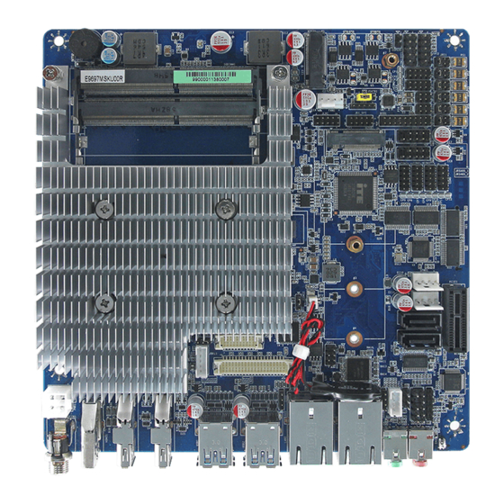
Page 17: Product Overview
User’s Manual 2.1 Product Overview Note: If M.2 Type B 3042/2242/2260/2280 using PCI-e x2 device, it requires OEM BIOS ME setting; hence PCI-e slot is not workable. EMX-SKLUP User’s Manual 17... - Page 18 EMX-SKLUP User’s Manual Note: SD card support list please refer to HW Storage Compatibility Test report. 18 EMX-SKLUP User’s Manual...
-
Page 19: Jumper And Connector List
FPT2 Miscellaneous setting connector 2 5 x 2 header, pitch 2.54mm SODIMM1/2 206-pin DDR4 SO-DIMM socket 5 x 2 header, pitch 2.54mm FAUD1 Front Audio connector 5 x 1 wafer, pitch 2.00mm JBKL1 LCD Inverter connector EMX-SKLUP User’s Manual 19... - Page 20 4 x 1 wafer, pitch 2.54mm SPWR1/2 I2C1 I2C connector 5 x 1 header, pitch 2.00mm HDMI1 HDMI connector LOUT1 Line-out audio jack MIC1 Mic-in audio jack DMIC1 Mic-in connector 5 x 1 header, pitch 2.54mm SD card slot 20 EMX-SKLUP User’s Manual...
- Page 21 User’s Manual SIM1 SIM card slot CPU fan connector 4 x 1 wafer, pitch 2.54mm FAN1 EMX-SKLUP User’s Manual 21...
-
Page 22: Setting Jumpers & Connectors
2.3 Setting Jumpers & Connectors 2.3.1 Serial port 1/2/3/4/5/6 pin9 signal select (JRI1/JRI2/JRI3/JRI4/JRI5/JRI6) Ring* JRI1 JRI2 JRI3 JRI4 +12V JRI5 JRI6 * Default 2.3.2 LVDS Back Light power selection (JSBKL1) PWM Mode* DC Mode * Default 22 EMX-SKLUP User’s Manual... -
Page 23: At/Atx Power Mode Select (Jsatx1)
User’s Manual 2.3.3 AT/ATX Power Mode Select (JSATX1) ATX* * Default 2.3.4 Clear CMOS (JCOMS1) Protect* Clear CMOS * Default EMX-SKLUP User’s Manual 23... -
Page 24: Lcd Inverter Connector (Jbkl1)
EMX-SKLUP User’s Manual 2.3.5 LCD Inverter connector (JBKL1) Signal Max current LVDS_BKLTCTL LVDS_BKLT_EN +12V 2.3.6 General purpose I/O connector (DIO1) Signal PIN PIN Signal SMB_CLK_S SMB_DATA_S 20 +5V(Max current = 0.5A) 24 EMX-SKLUP User’s Manual... -
Page 25: Serial Port 1/2 Connector (Com1/2)
User’s Manual 2.3.7 Serial port 1/2 connector (COM1/2) COM1 COM2 Signal PIN PIN Signal (Max current = 0.5A) 2.3.8 Serial port 3/4/5/6 connector (COM3/4/5/6) Signal PIN PIN Signal (Max current = 0.5A) EMX-SKLUP User’s Manual 25... -
Page 26: Serial Port 1/2 Rs485/422 Mode Connector (Jrs485_1/2)
EMX-SKLUP User’s Manual 2.3.9 Serial Port 1/2 RS485/422 Mode connector (JRS485_1/2) JRS485_1 JRS485_2 Signal PIN PIN Signal 485_422TX- 422RX- 485_422TX+ 422RX+ (Max current = 0.5A) 2.3.10 SATA Power connector 1/2 (SPWR1/2) SPWR1 SPWR2 Signal Max current +V5S_SATA +V12S_SATA 26 EMX-SKLUP User’s Manual... -
Page 27: Power Connector (Pwr1)
User’s Manual 2.3.11 Power connector (PWR1) Signal Signal +VIN +VIN 2.3.12 USB connector 3 (USB3) Signal Signal +V5A_USB78 +V5A_USB78 USB_DN7 USB_DN8 USB_DP7 USB_DP8 EMX-SKLUP User’s Manual 27... -
Page 28: Usb Connector 4 (Usb4)
EMX-SKLUP User’s Manual 2.3.13 USB connector 4 (USB4) Signal Signal +V5A_USB78 +V5A_USB78 USB_DN9 USB_DN10 USB_DP9 USB_DP10 2.3.14 Battery connector (BT1) Signal 28 EMX-SKLUP User’s Manual... -
Page 29: Lvds Connector (Lvds1)
LVDS_DATA0_N 12 11 LVDS_DATA1_N LVDS_DATA2_P 16 15 LVDS_DATA3_P LVDS_DATA2_N 18 17 LVDS_DATA3_N LVDS_DATA4_P 22 21 LVDS_DATA5_P LVDS_DATA4_N 24 23 LVDS_DATA5_N LVDS_DATA6_P 28 27 LVDS_DATA7_P LVDS_DATA6_N 30 29 LVDS_DATA7_N LVDS_CLK1_P LVDS_CLK2_P LVDS_ CLK1_N LVDS_ CLK2_N +12V +12V EMX-SKLUP User’s Manual 29... -
Page 30: Audio Connector (Faud1)
EMX-SKLUP User’s Manual 2.3.16 Audio connector (FAUD1) Signal PIN PIN Signal LINE2_JD LINE2_LIN SENSE_B MIC2_JD LINE2_RIN AUD_FRONT_DET MIC2_RIN MIC2_LIN 2.3.17 EC Debug (JEC_SPI) Signal PIN PIN Signal +3VSPI_EC EC_FSCE# EC_FSCK EC_FMISO EC_FMOSI EC_HOLD# EC_SMCLK EC_SMDAT 30 EMX-SKLUP User’s Manual... -
Page 31: Spi Connector (Jspi1)
User’s Manual 2.3.18 SPI connector (JSPI1) Signal PIN PIN Signal HOLD# SPI_SI SPI_SO SPI_CLK SPI0_CS0# +3.3A_SPI 2.3.19 Sony/Philips Digital Interface (SPDIF1) Signal SPDIF_OUT EMX-SKLUP User’s Manual 31... -
Page 32: Miscellaneous Setting Connector 1 (Fpt1)
1. Pin2 with GND: Control LVDS Backlight by use Variable Resistor. 2. BLK_UP with GND/BLK_DN with GND: Step control LVDS Backlight by use button and BIOS must to be set “BR Button”. (Please refer to page.61) 32 EMX-SKLUP User’s Manual... -
Page 33: Led Indicator Connector 1 (Led1)
User’s Manual 2.3.22 LED indicator connector 1 (LED1) Signal LAN1_1000#_LED LAN1_100#_LED LAN1_ACT_N LAN1_ACT_P 2.3.23 LED indicator connector 2 (LED2) Signal LAN2_1000#_LED LAN2_100#_LED LAN2_ACT_N LAN2_ACT_P EMX-SKLUP User’s Manual 33... -
Page 34: Speaker Connector (Spk1)
EMX-SKLUP User’s Manual 2.3.24 Speaker connector (SPK1) Signal SPK_R- SPK_R+ SPK_L- SPK_L+ 2.3.25 Mic-in connector (DMIC1) Signal DMIC_CLK DMIC_DATA +3.3V 34 EMX-SKLUP User’s Manual... -
Page 35: I2C Connector (I2C1)
I2C0_CLK I2C0_DATA 2.3.27 eDP_Panel connector (EDP1) Signal PIN PIN Signal EDP_PanelTXN0 EDP_PanelTXN3 EDP_PanelTXP0 EDP_PanelTXP3 EDP_PanelTXN1 EDP_PanelTXP1 11 12 EDP_PanelAUXN 14 EDP_PanelAUXP EDP_PanelTXN2 15 Note: EDP_PanelTXP2 17 EDP_Panel_HPD Default 3.3V. +V3512_EDP +V3512_EDP This a BOM optional part. EMX-SKLUP User’s Manual 35... -
Page 36: Lpc Connector (Jlpc)
EMX-SKLUP User’s Manual 2.3.28 LPC connector (JLPC) Signal PIN PIN Signal LPC_AD0 +3.3V LPC_AD1 PCH_PLTRST# LPC_AD2 LPC_FRAME# LPC_AD3 LPC_CLK LPC_SERIRQ 2.3.29 CPU fan connector (FAN1) Signal +12V CPU_FANIN FAN_PWM0 36 EMX-SKLUP User’s Manual... -
Page 37: Hdmi1/Dp1/Dp2/Lvds1
Note: HDMI1 and DP1 share one circuit for display output depending on which monitor input is engaged. (Only one display port can be output, HDMI1 or DP1) Triple display: HDMI & DP++ & LVDS DP & DP++ & LVDS EMX-SKLUP User’s Manual 37... -
Page 38: Bios Setup
EMX-SKLUP User’s Manual 3.BIOS Setup 38 EMX-SKLUP User’s Manual... -
Page 39: Introduction
If you do not press the keys at the correct time and the system does not boot, an error message will be displayed and you will again be asked to. Press F1 to Continue, DEL to enter SETUP EMX-SKLUP User’s Manual 39... -
Page 40: Using Setup
Note: Some of the navigation keys differ from one screen to another. To Display a Sub Menu Use the arrow keys to move the cursor to the sub menu you want. Then press <Enter>. A “” pointer marks all sub menus. 40 EMX-SKLUP User’s Manual... -
Page 41: Getting Help
BIOS Vendor and your systems manufacturer to provide the absolute maximum performance and reliability. Even a seemingly small change to the chipset setup has the potential for causing you to use the override. EMX-SKLUP User’s Manual 41... -
Page 42: Bios Setup
<Enter> to accept and enter the sub-menu. 3.6.1 Main Menu This section allows you to record some basic hardware configurations in your computer and set the system clock. 42 EMX-SKLUP User’s Manual... -
Page 43: System Language
Visit the Avalue website (www.avalue.com.tw) to download the latest product and BIOS information. 3.6.2 Advanced Menu This section allows you to configure your CPU and other system devices for basic operation through the following sub-menus. EMX-SKLUP User’s Manual 43... -
Page 44: Trusted Computing
3.6.2.1 Trusted Computing Item Options Description Enables or Disables BIOS support for security Disable Security Device Support devices. O.S. will not show Security Device. TCG EFI Enable[Default] protocol and INT1A interface will not be available. 3.6.2.2 APCI Settings 44 EMX-SKLUP User’s Manual... -
Page 45: Amt Configuration
Last state Disabled[Default], 30 sec 40 sec 50 sec Watch Dog Select WatchDog. 1 min 2 min 10 min 30 min Disabled Enabled/Disabled USB Standby Power USB Standby Power Setting Enabled[Default] during S3/S4/S5. 3.6.2.3 AMT Configuration EMX-SKLUP User’s Manual 45... -
Page 46: Pch-Fw Configuration
This option just controls the BIOS extension execution. Enabled[Default], If enabled, this requires additional firmware in the SPI device. Disabled[Default] Un-Configure ME OEMFlag Bit 15: Un-Configure ME without password. Enabled, 3.6.2.4 PCH-FW Configuration 3.6.2.4.1 Firmware Update Configuration 46 EMX-SKLUP User’s Manual... -
Page 47: It8528 Super Io Configuration
Set Parameters of Serial Port 3 (COMC). Serial Port 4 Configuration Set Parameters of Serial Port 4 (COMD). Serial Port 5 Configuration Set Parameters of Serial Port 5 (COME). Serial Port 6 Configuration Set Parameters of Serial Port 6 (COMF). EMX-SKLUP User’s Manual 47... -
Page 48: Serial Port 1 Configuration
3.6.2.5.1 Serial Port 1 Configuration Item Option Description Enabled[Default], Serial Port Enable or Disable Serial Port (COM). Disabled UART 232[Default], UART 232 422 485 UART 422, Change the Serial Port as RS232/422/485. UART 485 3.6.2.5.2 Serial Port 2 Configuration 48 EMX-SKLUP User’s Manual... -
Page 49: Serial Port 3 Configuration
UART 232 422 485 UART 422, Change the Serial Port as RS232/422/485. UART 485 3.6.2.5.3 Serial Port 3 Configuration Item Option Description Enabled[Default], Serial Port Enable or Disable Serial Port (COM). Disabled 3.6.2.5.4 Serial Port 4 Configuration EMX-SKLUP User’s Manual 49... -
Page 50: Serial Port 5 Configuration
Item Option Description Enabled[Default], Serial Port Enable or Disable Serial Port (COM). Disabled 3.6.2.5.5 Serial Port 5 Configuration Item Option Description Enabled[Default], Enable or Disable Serial Port Serial Port Disabled (COM). 3.6.2.5.6 Serial Port 6 Configuration 50 EMX-SKLUP User’s Manual... -
Page 51: H/W Monitor
User’s Manual Item Option Description Enabled[Default], Enable or Disable Serial Port Serial Port Disabled (COM). 3.6.2.6 H/W Monitor Item Options Description Disabled[Default], Smart Fan Function Enable or Disable Smart Fan. Enabled 3.6.2.6.1 Smart Fan Mode Configuration EMX-SKLUP User’s Manual 51... -
Page 52: S5 Rtc Wake Settings
Wake up hour 0-23 3pm. Select 0-23 For example enter 3 for 3am and 15 for Wake up minute 0-59 3pm. Select 0-23 For example enter 3 for 3am and 15 for Wake up second 0-59 3pm. 52 EMX-SKLUP User’s Manual... -
Page 53: Serial Port Console Redirection
Select FixedTime, system will wake on the Wake system from S5 Fixed Time hr::min::sec specified. Select DynamicTime, Dynamic Time[Default] System will wake on the current time + Increase minutes(s). Wake up minute increase 1-5. 3.6.2.8 Serial Port Console Redirection EMX-SKLUP User’s Manual 53... -
Page 54: Com1
They can be used as and additional data bit. Stop bits indicate the end of a serial data packet. 1[Default] Stop Bits (A start bit indicates the beginning). The standard setting is 1 stop bit. Communication 54 EMX-SKLUP User’s Manual... - Page 55 Console Redirection is disabled before booting Redirection After BIOS Always Enable[Default] to legacy OS. When Always Enabled is POST Boot Loader selected, then Legacy Console Redirection is enabled for legacy OS. Default setting for this option is set to Always Enable. EMX-SKLUP User’s Manual 55...
-
Page 56: Cpu Configuration
EMX-SKLUP User’s Manual 3.6.2.9 CPU Configuration Use the CPU configuration menu to view detailed CPU specification and configure the CPU. Item Options Description All[Default] Number of cores to enable in each processor Active Processor Cores package. 56 EMX-SKLUP User’s Manual... -
Page 57: Intel Txt Information
Enabled[Default] Virtualization Technology. Disabled, Turbo Mode Turbo Mode. Enabled[Default] Disabled, CPU C states Enable or disable CPU states. Enabled[Default] C0/C1 Package C State limit Package C State limit. Auto[Default] 3.6.2.10 Intel TXT Information EMX-SKLUP User’s Manual 57... -
Page 58: Sata Configuration
SATA Controller Speed Gen2 controller can support. Gen3 Disabled, Port1/2 Enable/Disable SATA Port. Enabled[Default] Hard Disk Drive Identify the SATA port is connected to Solid SATA Device Type Solid State Drive[Default] State Drive or Hard Disk Drive. 58 EMX-SKLUP User’s Manual... -
Page 59: Network Stack Configuration
Enabled[Default] IPV6 PXE boot option will not be created. Wait time to press ESC key to abort the PXE PXE boot wait time boot. Number of times presence of media will be Media detect count checked. EMX-SKLUP User’s Manual 59... -
Page 60: Csm Configuration
Legacy[Default] Do not launch Controls the execution of UEFI and Legacy Video UEFI Video OpROM. Legacy[Default] Do not launch Determines OpROM execution policy for Other PCI devices UEFI devices other than Network, Storage, or Legacy[Default] Video. 60 EMX-SKLUP User’s Manual... -
Page 61: Sdio Configuration
SDIO Access Mode PIO mode. DMA Option: Access SD device SDMA in DMA mode. PIO Option: Access SD device in PIO mode. 3.6.2.15 USB Configuration The USB Configuration menu helps read USB information and configures USB settings. EMX-SKLUP User’s Manual 61... - Page 62 Mass storage device emulation type. ‘AUTO’ Auto[Default] Floppy enumerates devices according to their media format. Optical drives are emulated as ‘CDROM’, Mass Storage Devices Forced FDD Hard Disk drives with no media will be emulated according CD-ROM to a drive type. 62 EMX-SKLUP User’s Manual...
-
Page 63: Chipset
User’s Manual 3.6.3 Chipset 3.6.3.1 System Agent (SA) Configuration Item Option Description Enabled[Default] VT-d VT-d capability. Disabled EMX-SKLUP User’s Manual 63... -
Page 64: Graphics Configuration
1366x768 24/1 1920x1080 24/2 1680x1050 24/2 BIOS[Default] LVDS Brightness Control Method. BR Button Brightness Control Method 1.BIOS 2.Brightness Button 3.Variable Resistor 4.OS Driver. OS driver LVDS Back Light PWM Select LVDS back light PWM duty. 100%[Default] 64 EMX-SKLUP User’s Manual... -
Page 65: Memory Configuration
Select LVDS back light PWM Frequency Frequency. 3.6.3.1.2 Memory Configuration Item Option Description Maximum Value of TOLUD. Dynamic Dynamic[Default] assignment would adjust TOLUD Max TOLUD /1GB/1.25GB/1.5GB/1.75GB automatically based on largest MMIO length /2GB/2.25GB/2.5GB/2.75GB of installed graphic controller. EMX-SKLUP User’s Manual 65... -
Page 66: Pch-Io Configuration
EMX-SKLUP User’s Manual 3.6.3.2 PCH-IO Configuration Item Option Description Disabled PCH LAN Controller Enable or disable onboard NIC. Enabled[Default] 3.6.3.2.1 PCI Express Configuration 66 EMX-SKLUP User’s Manual... - Page 67 L0s State AUTO – BIOS auto ASPM Support configure DISABLE – Disables ASPM. L0sL1 Auto, Disabled[Default] L1.1 L1 Substates PCI Express L1 Substates settings. L1.2 L1.1 & L1.2, Auto[Default] Gen1 PCIe Speed Select PCI Express port speed. Gen2 Gen3 EMX-SKLUP User’s Manual 67...
- Page 68 L0s State AUTO – BIOS auto ASPM Support configure DISABLE – Disables ASPM. L0sL1 Auto, Disabled L1.1 L1 Substates PCI Express L1 Substates settings. L1.2 L1.1 & L1.2[Default] Auto[Default] Gen1 PCIe Speed Select PCI Express port speed. Gen2 Gen3 68 EMX-SKLUP User’s Manual...
- Page 69 L0s State AUTO – BIOS auto ASPM Support configure DISABLE – Disables ASPM. L0sL1 Auto, Disabled L1.1 L1 Substates PCI Express L1 Substates settings. L1.2 L1.1 & L1.2[Default] Auto[Default] Gen1 PCIe Speed Select PCI Express port speed. Gen2 Gen3 EMX-SKLUP User’s Manual 69...
- Page 70 L0s State AUTO – BIOS auto ASPM Support configure DISABLE – Disables ASPM. L0sL1 Auto, Disabled L1.1 L1 Substates PCI Express L1 Substates settings. L1.2 L1.1 & L1.2[Default] Auto[Default] Gen1 PCIe Speed Select PCI Express port speed. Gen2 Gen3 70 EMX-SKLUP User’s Manual...
- Page 71 L0s State AUTO – BIOS auto ASPM Support configure DISABLE – Disables ASPM. L0sL1 Auto, Disabled L1.1 L1 Substates PCI Express L1 Substates settings. L1.2 L1.1 & L1.2[Default] Auto[Default] Gen1 PCIe Speed Select PCI Express port speed. Gen2 Gen3 EMX-SKLUP User’s Manual 71...
-
Page 72: Usb Configuration
Disabled[Default], and root ports for faster enumeration. Option to disable Compliance Mode. Default FALSE[Default], XHCI Disable Compliance Mode is FALSE to not disable Compliance Mode. TRUE Set TRUE to disable Compliance Mode. 3.6.3.2.3 HD Audio Configuration 72 EMX-SKLUP User’s Manual... -
Page 73: Scs Configuration
Amplifier Gain Amplifier Gain. 32db 36db 3.6.3.2.4 SCS Configuration Item Option Description Disabled[Default] eMMC 5.0 Controller Enable or Disable SCS eMMC 5.0 Controller. Enabled Disabled SDCard 3.0 Controller Enable or Disable SCS SDHC 3.0 Controller. Enabled[Default] EMX-SKLUP User’s Manual 73... -
Page 74: Security
EMX-SKLUP User’s Manual 3.6.4 Security Administrator Password Set setup Administrator Password User Password Set User Password 74 EMX-SKLUP User’s Manual... -
Page 75: Secure Boot Menu
Secure Boot in User mode with enrolled Platform Key(PK) Enabled 2.CSM function is disabled. Secure Boot mode selector. ‘Custom’ Mode Standard Secure Boot Mode enables users to change Image Execution policy Custom[Default] and manage Secure Boot Keys. EMX-SKLUP User’s Manual 75... -
Page 76: Key Management
EMX-SKLUP User’s Manual 3.6.4.1.1 Key Management Item Option Description Disabled[Default] Install factory default Secure Boot keys when Provision Factory Default keys Enabled System is in Setup Mode. 3.6.5 Boot 76 EMX-SKLUP User’s Manual... -
Page 77: Save And Exit
Reset system setup without saving any changes. 3.6.6.3 Restore Defaults Restore/Load Default values for all the setup options. 3.6.6.4 Launch EFI Shell from filesystem device Attempts to Launch EFI Shell application (Shell.efi) from one of the available filesystem devices. EMX-SKLUP User’s Manual 77... -
Page 78: Drivers Installation
EMX-SKLUP User’s Manual 4. Drivers Installation Note: Installation procedures and screen shots in this section are for your reference and may not be exactly the same as shown on your screen. 78 EMX-SKLUP User’s Manual... -
Page 79: Install Chipset Driver
Windows 10 operation system. If the warning message appears while the installation process, click Continue to go on. Step 3. Click Install. Step 4. Complete setup. Step1. Click Next. Step 2. Click Accept. EMX-SKLUP User’s Manual 79... -
Page 80: Install Vga Driver
Windows 10 operation system. Step 3. Click Next. Step 1. Click Next to continue installation. Step 4. Click Next. Step 5. Click Finish to complete setup. Step 2. Click Yes to accept license agreement. 80 EMX-SKLUP User’s Manual... -
Page 81: Install Serial Io Driver
Windows 10 operation system. Step 3. Click Next. Step 1. Click Next to continue installation. Step 4. Click Next. Step 2. Click Next. Step 5. Click Finish to complete setup. EMX-SKLUP User’s Manual 81... -
Page 82: Install Me Driver
Note: The installation procedures and screen shots in this section are based on Windows 10 operation system. Step 3. Click Next. Step 4. Click Finish to complete setup. Step 1. Click Next to continue setup. Step 2. Click Next. 82 EMX-SKLUP User’s Manual... -
Page 83: Install Audio Driver (For Realtek Alc892 Hd Audio)
Windows 10 operation system. If the warning message appears while the installation process, click Continue to go on. Step1. Click Next to Install. Step 2. Click Finish to complete setup. EMX-SKLUP User’s Manual 83... -
Page 84: Install Lan Driver
Note: The installation procedures and screen shots in this section are based on Windows 10 operation system. Step 3. Click Next. Step 4. Click Yes. Step 1. Click Next to continue installation. Step 5. Click Install. Step 2. Click Next. 84 EMX-SKLUP User’s Manual... - Page 85 User’s Manual Step 6. Click Finish to complete setup. EMX-SKLUP User’s Manual 85...
-
Page 86: Install Rst Driver
Note: The installation procedures and screen shots in this section are based on Windows 10 operation system. Step 3. Click Next. Step 1. Click Next to continue installation. Step 4. Click Next. Step 2. Click Next. Step 5. Click Next. 86 EMX-SKLUP User’s Manual... - Page 87 User’s Manual Step 6. Click Finish to complete setup. EMX-SKLUP User’s Manual 87...
-
Page 88: Mechanical Drawing
EMX-SKLUP User’s Manual 5. Mechanical Drawing 88 EMX-SKLUP User’s Manual... - Page 89 User’s Manual Unit: mm EMX-SKLUP User’s Manual 89...
- Page 90 EMX-SKLUP User’s Manual Unit: mm 90 EMX-SKLUP User’s Manual...
- Page 91 User’s Manual Unit: mm EMX-SKLUP User’s Manual 91...
- Page 92 EMX-SKLUP User’s Manual Unit: mm 92 EMX-SKLUP User’s Manual...
Need help?
Do you have a question about the EMX-SKLUP and is the answer not in the manual?
Questions and answers