Table of Contents
Advertisement
Quick Links
THE UNITED KINGDOM VEHICLE APPROVAL AUTHORITY
Approval No: 10R-035487
1.
Make (trade name of manufacturer): Directed Electronics
2.
Type and general commercial description(s): 350HV (426V), 426P Python 460HP 1 way,
Matrix +1 p/n 3105X, Matrix 1X p/n 3305X, 350 plus p/n 3105V, Responder 350 p/n 3305V,
3305P Python 460 two way and 3105P Python 460 max 1 way
3.
Means of identification of type, if marked on the component
3.1
Location of that marking: On top of unit
4.
Category of vehicle: Not applicable
5.
Name and address of manufacturer:
Directed Electronics
1 Viper Way
Vista
CA 92081
United Sates of America
6.
In the case of components and separate technical units, location and method of affixing of the
ECE approval mark: Printed on Sticker on top of unit
7.
Address(es) of assembly plant(s):
Nutek
No.167, Lane 235
BauChiau Road
ShinDian City
Taipei County 231
Taiwan
EAK216611
COMMUNICATION CONCERNING THE APPROVAL GRANTED OF A TYPE
OF ELECTRICAL/ELECTRONIC SUB-ASSEMBLY
REGULATION NO: 10 AS AMENDED BY THE 02 SERIES OF
AMENDMENTS
An executive agency of the Department for Transport
October Version 3
(1)
WITH REGARD TO
(1)
Sticker on base of unit
4171
24-Mar-10
Advertisement
Chapters
Table of Contents

Related Manuals for Clifford Concept 650


Summary of Contents for Clifford Concept 650
- Page 1 4171 THE UNITED KINGDOM VEHICLE APPROVAL AUTHORITY COMMUNICATION CONCERNING THE APPROVAL GRANTED OF A TYPE OF ELECTRICAL/ELECTRONIC SUB-ASSEMBLY WITH REGARD TO REGULATION NO: 10 AS AMENDED BY THE 02 SERIES OF AMENDMENTS Approval No: 10R-035487 Make (trade name of manufacturer): Directed Electronics Type and general commercial description(s): 350HV (426V), 426P Python 460HP 1 way, Matrix +1 p/n 3105X, Matrix 1X p/n 3305X, 350 plus p/n 3105V, Responder 350 p/n 3305V, 3305P Python 460 two way and 3105P Python 460 max 1 way...
- Page 2 ECE REGULATION NO: 10.03 Additional information (where applicable): See Appendix Technical service responsible for carrying out the tests: SGS UK Limited Date of test report: 2 March 2010 Number of test report: AUT130731/1/GH/10 Remarks (if any): See Appendix Place: BRISTOL Date: 24 MARCH 2010 Signature: A.
- Page 3 ECE REGULATION NO: 10.03 Appendix to Type Approval Communication Certificate No: 10R-035487 concerning the type approval of an electrical/electronic sub-assembly under Regulation No: 10 Additional information 1.1. Electrical system rated voltage: 12V. pos/neg ground This ESA can be used on any vehicle type with the following restrictions: 12V. pos/neg ground 1.2.1 Installation conditions, if any: Supplied with the product This ESA can be used only on the following vehicle types: Not applicable...
- Page 4 REG 10.3 ANNEX 2B. INFORMATION DOCUMENT FOR TYPE-APPROVAL OF AN ELECTRIC/ELECTRONIC SUB-ASSEMBLY WITH RESPECT TO ELECTRONMAGNETIC COMPATIBILITY Make (trade name of manufacturer):Directed Electronics Type: 350HV (426V), 426P Python 460HP 1 way, Matrix +1 p/n 3105X, Matrix 1X p/n 3305X, 350 plus p/n 3105V, Responder 350 p/n 3305V, 3305P Python 460 two way & 3105P Python 460 max 1 way.
- Page 5 Concept 650 MkII Wallet Quick Reference Card system disarm To disarm the system without a trans- mitter, turn the key to the ON posi- tion and enter your PIN code. quick reference remote functions valet mode entry 5-button custom function...
- Page 6 G426V_2008_08a.qxd 8/13/2008 10:22 AM Page 1 350HV ➤ Owner’s Guide 24-Mar-10...
-
Page 7: Limited Lifetime Consumer Warranty
G426V_2008_08a.qxd 8/13/2008 10:22 AM Page i limited lifetime consumer warranty Directed Electronics. (“Directed”) promises to the original purchaser to repair or replace (at Directed’s election) with a comparable reconditioned model any Directed unit (here- after the “unit”), excluding without limitation the siren, the remote transmitters, the asso- ciated sensors and accessories, which proves to be defective in workmanship or material under reasonable use during the lifetime of the vehicle provided the following conditions are met: the unit was purchased from an authorized Directed dealer, the unit was profes-... - Page 8 G426V_2008_08a.qxd 8/13/2008 10:22 AM Page ii CLAIM OR A DISPUTE INVOLVING DIRECTED OR ITS SUBSIDIARY, THE VENUE SHALL BE SAN DIEGO COUNTY IN THE STATE OF CALIFORNIA. CALIFORNIA STATE LAWS AND APPLICABLE FEDERAL LAWS SHALL APPLY AND GOVERN THE DISPUTE. THE MAXIMUM RECOVERY UNDER ANY CLAIM AGAINST DIRECTED SHALL BE STRICTLY LIMITED TO THE AUTHORIZED DIRECTED DEALER’S PURCHASE PRICE OF THE UNIT.
-
Page 9: Table Of Contents
G426V_2008_08a.qxd 8/13/2008 10:22 AM Page 1 table of contents s s t t a a n n d d a a r r d d t t r r a a n n s s m m i i t t t t e e r r c c o o n n f f i i g g u u r r a a t t i i o o n n ................2 2 e e x x p p a a n n d d e e d d t t r r a a n n s s m m i i t t t t e e r r c c o o n n f f i i g g u u r r a a t t i i o o n n * * . -
Page 10: Standard Transmitter Configuration
G426V_2008_08a.qxd 8/13/2008 10:22 AM Page 2 standard transmitter configuration controls the A A r r m m / / D D i i s s a a r r m m function. controls the P P a a n n i i c c function. controls S S i i l l e e n n t t M M o o d d e e ™... -
Page 11: System Maintenance
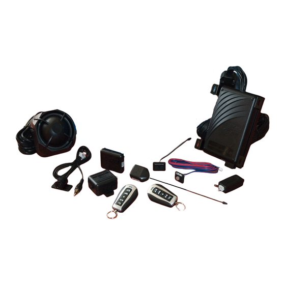
G426V_2008_08a.qxd 8/13/2008 10:22 AM Page 3 what is included ➤ One control module ➤ A pair of three-button transmitters ➤ A Stinger® Doubleguard® dual-stage shock sensor (on- board the control module) ➤ The Revenger® Soft Chirp® six-tone programmable siren ➤ Blue status LED indicator light ➤... -
Page 12: Your Warranty
G426V_2008_08a.qxd 8/13/2008 10:22 AM Page 4 that will last approximately one year under normal use. When the battery weakens, operating range will be reduced and the LED on the remote will dim. ➜ your warranty Your warranty registration must be returned and the bar code serial number must not be removed. -
Page 13: Standard Configuration
G426V_2008_08a.qxd 8/13/2008 10:22 AM Page 5 transmitter functions The system uses a computer-based learn routine to learn the transmitter buttons. This makes it possible to assign any trans- mitter button to any system function. The transmitter initially comes programmed with Standard Configuration, but may also be customized by an authorized dealer. -
Page 14: Expanded Configuration
G426V_2008_08a.qxd 8/13/2008 10:22 AM Page 6 Buttons An optional auxiliary convenience or expansion function that you have added to your system can be activated by pressing these buttons simultaneously. The auxiliary output controls_________________________. ➜ Expanded configuration (Available with optional four-button transmitter.) Button The arming function is controlled by pressing this button for one second. -
Page 15: Active Arming
G426V_2008_08a.qxd 8/13/2008 10:22 AM Page 7 Buttons An optional auxiliary convenience or expansion function that you have added to your system can be activated by pressing these buttons simultaneously. The auxiliary output controls_________________________. using your system The buttons used in the instructions in this manual correspond to the standard configuration. -
Page 16: Passive Arming
G426V_2008_08a.qxd 8/13/2008 10:22 AM Page 8 ➜ passive arming The system also can be programmed to arm itself automatically (called passive arming). If the system is programmed for passive arming, it will automatically arm 30 seconds after the ignition is turned off and the system "sees"... -
Page 17: Multi-Level Security Arming
G426V_2008_08a.qxd 8/13/2008 10:22 AM Page 9 ➤ If a door is opened, the system will immediately start chirping the siren and flashing the parking lights. Three seconds later, the siren output changes to a continuous blast. This progressive response gives you time to disarm the sys- tem with your transmitter if you inadvertently open the door while the system is armed, while still providing an instant response (even if the door is immediately closed). -
Page 18: Arming While Driving
G426V_2008_08a.qxd 8/13/2008 10:22 AM Page 10 ➤ Press a second time within five seconds: The siren chirps twice followed by a long chirp. Zone 2 is now bypassed. ➤ Press three times followed by a long chirp. Zone 4 is now bypassed. -
Page 19: Disarming
G426V_2008_08a.qxd 8/13/2008 10:22 AM Page 11 note: If programmed for the optional Vehicle Recovery System (VRS®) feature, arming with the transmitter will arm the VRS® feature. (See VRS® section of this guide.) ➜ disarming To disarm the system, press . You will hear two chirps, and the parking lights will flash twice. -
Page 20: Disarming Without A Transmitter
G426V_2008_08a.qxd 8/13/2008 10:22 AM Page 12 ➜ disarming without a transmitter This feature allows you to disarm the security system without the remote transmitter should it be lost, damaged, or disabled. In order to disarm the system without a remote transmitter, you must have the vehicle’s ignition key and know where the Valet button is located. -
Page 21: Silent Mode
G426V_2008_08a.qxd 8/13/2008 10:22 AM Page 13 ➜ silent mode To temporarily turn off the arm or disarm chirps, use Silent Mode™. Simply press for less than one second before arming or disarming, and the confirmation chirp(s) will be elim- inated for that one operation only. If you want the arm/disarm chirps turned off permanently, your dealer can do this for you. -
Page 22: Nuisance Prevention® Circuitry
G426V_2008_08a.qxd 8/13/2008 10:22 AM Page 14 To enter or exit Valet Mode: 1. Turn the ignition on. 2. Turn the ignition off. 3. Press and release the Valet DRW-35 switch within 10 seconds. The status LED will light solidly if you are entering Valet Mode, and it will go out if you are exiting Valet Mode. - Page 23 G426V_2008_08a.qxd 8/13/2008 10:22 AM Page 15 If the bypassed sensor tries to trigger the system while it is being bypassed, the 60-minute bypass period will start over. This ensures that a sensor that continually triggers will remain bypassed. Doors are covered by NPC ®...
-
Page 24: Arming Diagnostics
G426V_2008_08a.qxd 8/13/2008 10:22 AM Page 16 ➜ arming diagnostics If the system is armed while an input is active (door open, sensor triggering, etc.) the unit will chirp once when arming and then one more time a few seconds later. This is called Bypass Notification. -
Page 25: System Status Chirps
G426V_2008_08a.qxd 8/13/2008 10:22 AM Page 17 ➜ system status chirps The siren will chirp when arming/disarming the system. The pattern of chirps will audibly report the system’s status as described below. Action Number of Chirps Description System armed 1 (3 second delay), 1 System armed with zone active Disarm... -
Page 26: Table Of Zones
G426V_2008_08a.qxd 8/13/2008 10:22 AM Page 18 ➜ table of zones The zone number is the number of LED flashes used by the system to identify that input. The standard input assignments are listed below, along with spaces to write in any optional sensors or switches you have had installed. -
Page 27: Code Hopping
G426V_2008_08a.qxd 8/13/2008 10:22 AM Page 19 note: Your system stores the last two triggered zones in memory. If your system has been triggered but the LED has been reset by turning on the ignition, your dealer can still recall the last two zones that were triggered. Contact your dealer for details. -
Page 28: Owner Recognition
G426V_2008_08a.qxd 8/13/2008 10:22 AM Page 20 high frequency Your system transmits and receives at 434 MHz. This provides a cleaner spectrum with less interference and a more stable signal. Enjoy a phenomenal increase in range – even in areas with high radio interference. -
Page 29: Rapid Resume Logic
G426V_2008_08a.qxd 8/13/2008 10:22 AM Page 21 rapid resume logic This Directed system will store its current state to non-volatile memory. If power is lost and then reconnected, the system will recall the stored state from memory. This means if the unit is in Valet Mode and the battery is disconnected for any reason, such as servicing the car, when the battery is reconnected the unit will still be in Valet Mode. - Page 30 G426V_2008_08a.qxd 8/13/2008 10:22 AM Page 22 programming options Programming options control what your system does during normal operation, and require few or no additional parts. However, some may require additional installation labor. The following is a list of the program settings, with the factory settings in B B o o l l d d : : ➤...
- Page 31 G426V_2008_08a.qxd 8/13/2008 10:22 AM Page 23 note: When programmed for passive arming and active lock, if the system is disarmed without a door being opened, the system will relock the doors when it passive- ly rearms. ➤ Panic mode e e n n a a b b l l e e d d /disabled with the ignition on: Some states have laws against siren capability in a moving vehicle.
- Page 32 G426V_2008_08a.qxd 8/13/2008 10:22 AM Page 24 AED feature by turning the ignition key to the RUN posi- tion and pressing the Valet button the programmed number of times. AED is disabled when the system is in Valet Mode. note: This feature will only function if the Failsafe® Starter Kill relay has been installed.
-
Page 33: Installation Options
G426V_2008_08a.qxd 8/13/2008 10:22 AM Page 25 ➤ Valet pulse count: The number of presses of the Valet button required to disarm the security system, AED, or the VRS® system can be programmed from one to five presses. The default setting is o o n n e e press. ➤... - Page 34 G426V_2008_08a.qxd 8/13/2008 10:22 AM Page 26 ® vehicle recovery system (vrs The optional VRS feature is designed to ensure that any unau- ® thorized user of your vehicle (even if using your keys and remote control) will not be able to permanently separate you from your vehicle.
-
Page 35: Arming The Vrs
G426V_2008_08a.qxd 8/13/2008 10:22 AM Page 27 ➜ arming the vrs ® To arm the VRS , turn the ignition to the ON position and press ® the arm button on the remote transmitter for one second. The parking lights will flash and the siren will chirp once. This can be done before driving or while driving the vehicle. -
Page 36: Disarming The Vrs
G426V_2008_08a.qxd 8/13/2008 10:22 AM Page 28 after the siren chirps begin, the siren’s output will Fifteen seconds change to a continuous blast. From this point on, when the ignition key is turned off, the VRS ® will immediately turn on the starter kill. This will prevent the vehicle from being restarted, thus immobilizing it at that spot. - Page 37 G426V_2008_08a.qxd 8/13/2008 10:22 AM Page 29 If the system has entered the triggered sequence (siren has begun chirping), pressing the disarm button of the transmitter will not disarm VRS . To disarm the VRS during a VRS trigger ® ® ®...
- Page 38 G426V_2008_08a.qxd 8/13/2008 10:22 AM Page 30 glossary of terms The "brain" of your system. Usually hidden under Control Unit: the dash area of the vehicle. It houses the microprocessor which monitors your vehicle and controls all of the system's functions. : An automatic switch controlled by the secu- Fail-Safe Starter Kill rity system which prevents the vehicle’s starter from cranking...
- Page 39 G426V_2008_08a.qxd 8/13/2008 10:22 AM Page 31 : Hand-held, remote control which operates the Transmitter various functions of your system. : This is what happens when the Trigger or Triggered Sequence alarm "goes off" or "trips". The triggered response of your system consists of the siren sounding and parking light flashing for the programmed duration.
- Page 40 G426V_2008_08a.qxd 8/13/2008 10:22 AM Page 32 security & convenience expansions Here we have listed only some of the many expansion options available. Please contact your dealer for a complete explanation of all the options available to you. Metal on glass, glass cracking, and breaking glass Audio Sensor: each produce distinctive acoustic signatures.
- Page 41 G426V_2008_08a.qxd 8/13/2008 10:22 AM Page 33 The channel two output of the system can Power Trunk Release: operate a factory power release for the vehicle’s trunk or hatch. (An additional relay may be required.) If the factory release is not power activated, then Directed's 522T trunk release solenoid can often be added.
- Page 42 G426V_2008_08a.qxd 8/13/2008 10:22 AM Page 34 24-Mar-10...
- Page 43 G426V_2008_08a.qxd 8/13/2008 10:22 AM Page 35 QUICK REFERENCE GUIDE To arm using your remote You can activate, or arm, the system by pressing on your transmitter for ➤ one second. When the system arms, you will hear a short siren sound, or chirp, and the parking lights will flash once.
- Page 44 G426V_2008_08a.qxd 8/13/2008 10:22 AM Page 36 The company behind this system is Directed Electronics, Inc. Since its inception, Directed has had one purpose, to provide consumers with the finest ® vehicle security and car stereo products and accessories available. The recipient of nearly 100 patents and Innovations Awards in the field of advanced electronic technology, Directed is ISO 9001 registered.
- Page 45 G919730P_01-07.qxd 1/12/07 3:38 PM Page 1 MkII Concept 650 O O w w n n e e r r ’ ’ s s G G u u i i d d e e 24-Mar-10...
- Page 46 G919730P_01-07.qxd 1/12/07 3:38 PM Page i limited lifetime consumer warranty Directed Electronics ("Directed") promises to the original purchaser to repair or replace with a comparable reconditioned model any Directed unit (hereafter the "unit"), excluding without limitation the siren, the remote transmitters, the associated sensors and accessories, which proves to be defective in workmanship or material under reasonable use during the lifetime of the vehicle provided the following conditions are met: the unit was professionally installed and serviced by an authorised Directed dealer;...
- Page 47 Type of alarm installed Year, make, model and colour of the vehicle Vehicle registration number Vehicle identification number All security options installed on the vehicle trademarks and copyrights Bitwriter ® , Clifford ® , Code-Hopping ™ , Directed ® , Doubleguard ®...
- Page 48 G919730P_01-07.qxd 1/12/07 3:38 PM Page 1 contents limited lifetime warranty ..i high frequency ....18 what is included ... . .3 smart power up II .
- Page 49 G919730P_01-07.qxd 1/12/07 3:38 PM Page 2 security & convenience ..37 health check ....39 24-Mar-10...
-
Page 50: What Is Included
: : Your system MUST be installed by an Authorised dealer in accor- dance with the instructions we supply them. The Clifford Concept 650 MkII system is designed to be installed in any petrol or common rail diesel vehicle with a 12-volt battery. -
Page 51: System Maintenance
: : Making changes to the existing system will invalidate the certifi- cate of installation. system maintenance MkII The Concept 650 requires no specific maintenance. Your transmit- ter is powered by two miniature 3V lithium batteries that will last approximately one year under normal use. When the battery weakens, operating range will be reduced and the system will provide a low bat- tery warning chirp indication when disarming. -
Page 52: Transmitter Configurations
: : This manual describes the features and accessories that are included with your system along with information about compatible Clifford accessories that are not included. For a list of included acces- sories, please refer to the What Is Included section of this manual. -
Page 53: Transmitter Functions
G919730P_01-07.qxd 1/12/07 3:38 PM Page 6 transmitter functions This system uses computer-based code learning to learn the transmitter buttons. This makes it possible to assign any transmitter button to any system function. The transmitter initially comes programmed with stan- dard configuration, but may also be customised using the CliffNet Wizard PC program. - Page 54 G919730P_01-07.qxd 1/12/07 3:38 PM Page 7 Button, then Button Accessory C output is controlled by these buttons. Button twice, then Button These buttons activate/deactivate remote valet. Button twice, then Button These buttons disable the sensors. Button twice, then Button These buttons enter safe start mode for manual transmission vehicles and activate Autostart mode.
-
Page 55: Using Your System
G919730P_01-07.qxd 1/12/07 3:38 PM Page 8 using your system The buttons used in the instructions in this manual correspond to the standard transmitter configuration. If your transmitter has been custom configured, the icons on your transmitter buttons may not correspond to the indicated functions. -
Page 56: Disarming
G919730P_01-07.qxd 1/12/07 3:38 PM Page 9 not chirp. The early chirps provide you with a 25-second warning prior to arming. n n o o t t e e : : If any protected entry point (a door or a switch-protected boot or bonnet) is open, the system will not passively arm. -
Page 57: Disarming Without A Transmitter
G919730P_01-07.qxd 1/12/07 3:38 PM Page 10 disarming without a transmitter This feature allows you to disarm the system without the transmitter should it be lost, damaged, or disabled. In order to disarm without a transmitter, you must have the vehicle’s ignition key, know where the PlainView 2 Valet switch is located, and have the PIN code. -
Page 58: Transmitter Sensor Disable
G919730P_01-07.qxd 1/12/07 3:38 PM Page 11 transmitter sensor disable To temporarily disable a sensor input, arm the system, press twice and then . The lights will flash four times and all warn away trig- ger zones one, two, three, and eight are bypassed. Press the buttons again;... -
Page 59: Auxiliary Channel Bypass
G919730P_01-07.qxd 1/12/07 3:38 PM Page 12 auxiliary channel bypass Alarm sensor input zones one, two, three, and eight will be bypassed while a pulsed or timed auxiliary Output is active. disarm/valet mode Entering your pin code using the PlainView 2 Valet switch allows you to disarm the system or enter valet mode without using the transmit- ter. -
Page 60: Transmitter Valet Mode
G919730P_01-07.qxd 1/12/07 3:39 PM Page 13 3. After the last digit of the pin code is entered: a. To disarm the system: press and release b. To enter valet mode: Press and hold three seconds. The LED status indicator will illuminate continuously if you are entering Valet Mode and will turn off if you are exiting Valet Mode. -
Page 61: One-Time Auto-Arming Bypass
G919730P_01-07.qxd 1/12/07 3:39 PM Page 14 one-time auto-arming bypass This will bypass the auto arm feature once only. With the key, turn the ignition on, then off within two seconds. The siren will chirp once to confirm auto arming bypass. The system will not auto arm. -
Page 62: Multiple Event Total Recall
G919730P_01-07.qxd 1/12/07 3:39 PM Page 15 multiple event total recall This will report the last eight system triggers. Press and hold of the PlainView 2 Valet switch. While still holding , arm and disarm the system, then release the button. The LED will start to blink to indicate the most recent trigger and proceed down to the eighth trigger. -
Page 63: Disarming Diagnostics
G919730P_01-07.qxd 1/12/07 3:39 PM Page 16 The security system will ignore the input that was active when the sys- tem was armed, until the input goes away. Three seconds later the sys- tem will monitor that input normally. For example, if your vehicle has the boot open, and you arm the system, you will hear Bypass Notification chirps. -
Page 64: Table Of Zones
G919730P_01-07.qxd 1/12/07 3:39 PM Page 17 table of zones The zone number is the number of LED flashes used by the system to identify a specific input. The standard input assignments are listed below, along with spaces to write in any optional sensors or switches you have had installed. -
Page 65: High Frequency
G919730P_01-07.qxd 1/12/07 3:39 PM Page 18 high frequency Your system transmits and receives at 433 MHz. This provides a cleaner spectrum with less interference and a more stable signal. smart power up II This security system will store its current state to non-volatile memory. If power is lost and then reconnected the system will recall the stored state from memory. -
Page 66: Programming Options
G919730P_01-07.qxd 1/12/07 3:39 PM Page 19 Power Saver in Valet Mode: When the system enters Valet Mode the LED illuminates steadily. If the vehicle is not used (ignition is not turned on) for a period of one hour while the system is in Valet Mode, the LED will shut off. -
Page 67: Cliffnet Wizard Installation Software Programming
G919730P_01-07.qxd 1/12/07 3:39 PM Page 20 feature only works if passive arming has been programmed. Reset the system to all factory defaults Entry delay feature off or on Add or remove remote controls. BlackJax* feature off or on. Change PIN code. Custom configure the remote control. -
Page 68: Manual Programming Instructions
G919730P_01-07.qxd 1/12/07 3:39 PM Page 21 manual programming instructions It is a good idea to document changes by taking note of all feature changes made in programming mode. To enter the User Selectable Features programming: Ignition on - Turn the ignition to the run position or start the engine. -
Page 69: User Selectable Features
G919730P_01-07.qxd 1/12/07 3:39 PM Page 22 gramming mode has been exited. user selectable features Off / On Off/On/Quiet Off/Ignition/RPM Off/On Off/On Off/Ignition Off/On Off/On Off/On This feature is only available with optional IntelliStart connected. This feature is only available with optional SmartWindows connected. 5-button remote only. - Page 70 G919730P_01-07.qxd 1/12/07 3:39 PM Page 23 Auto-learn new five-button remote controls to the system in the stan- dard button configuration. Once you have entered the feature, press on the transmitter until you hear a confirmation chirp. Press again until you hear two chirps indicating the new remote is learned. auto (passive) arm - on/off Off: The transmitter must be used to arm the system.
-
Page 71: User Selectable Features Descriptions - Column Two
G919730P_01-07.qxd 1/12/07 3:39 PM Page 24 auto unlock - ignition/off Off: The doors will not automatically unlock when the igni- tion is turned off Ignition: The doors will automatically unlock as soon as the ignition is turned off. auto (passive) arm and lock - on/off Off: The doors will not lock when the system passively arms. - Page 72 G919730P_01-07.qxd 1/12/07 3:39 PM Page 25 entry delay on/off On: If the system has passively armed, it will not trigger for 15 seconds after a door is opened allowing the user to enter the vehicle and disarm the system via the PlainView 2 Valet switch.
-
Page 73: User Selectable Features Descriptions - Column Three
G919730P_01-07.qxd 1/12/07 3:39 PM Page 26 blackjax* on/off On: The system will enter BlackJax mode when triggered. Off: The system cannot enter BlackJax mode. user selectable features descriptions - column three The features in this column pertain to programming individual trans- mitter channels in custom configurations. - Page 74 G919730P_01-07.qxd 1/12/07 3:39 PM Page 27 accessory b output The transmitter channel programmed into this feature will activate the accessory output. silent mode The transmitter channel programmed into this feature will arm/disarm the system, but the siren will not chirp. remote valet The transmitter channel programmed into this feature will make the system enter/exit valet mode.
-
Page 75: Pin Programming
G919730P_01-07.qxd 1/12/07 3:39 PM Page 28 ters that have been lost, stolen, or incorrectly programmed into the system. After entering this feature press any button on the transmit- ter; the siren will chirp to indicate that all transmitters have been erased from memory. pin programming A PIN code can have one to four digits;... -
Page 76: Ultrasecure Auto-Immobiliser
G919730P_01-07.qxd 1/12/07 3:39 PM Page 29 Press and release two times, and then press once. You will hear two chirps. Wait for two siren chirps after a five second pause or five seconds after the last digit has been entered if using less than four digit code number. -
Page 77: Auto-Immobilisation Sequence
G919730P_01-07.qxd 1/12/07 3:39 PM Page 30 auto-immobilisation sequence Turn ignition off or disarm alarm After 30 seconds the systems Immobilisation circuits activate and engage the starter and ignition interrupt LED flashes at ½ normal speed Disarming auto-immobilisation To disarm auto-immobilisation when active, follow any of the sequences listed below. -
Page 78: Blackjax* Feature
3:39 PM Page 31 blackjax* feature Clifford's exclusive BlackJax feature provides a safe and effective means of recovering your vehicle after a carjacking by monitoring the door input, brakes, and engine speed. Simply get out of the vehicle and let the thief drive away. - Page 79 G919730P_01-07.qxd 1/12/07 3:39 PM Page 32 Press and release brake pedal. System sees the brake pedal pressed. System then begins monitoring the engine speed. System sees the engine speed at two times idle. BlackJax* begins 20 second countdown. After a 20 second countdown: 5 siren chirps as reminder to enter PIN code.
-
Page 80: Blackjax* Deactivation Sequence
G919730P_01-07.qxd 1/12/07 3:39 PM Page 33 blackjax* deactivation sequence To deactivate BlackJax turn the key on and then enter the PIN code at any time. bypass blackjax temporarily This feature allows you to easily bypass BlackJax activation when anoth- er person drives your vehicle that should not know your PIN code. (IE: valet parking, mechanic) Bypass BlackJax temporarily Turn ignition on. -
Page 81: Blackjax* Off Warning Indicator
G919730P_01-07.qxd 1/12/07 3:39 PM Page 34 Turn ignition off, siren chirps 3 times as confirmation of exit- ing programming. n n o o t t e e : : If ignition remains on after entering PIN code and no action for 10 seconds, unit will automatically exit programming mode without chirps. -
Page 82: Glossary Of Terms
For sensitivity adjustments for all sensors, please return to your installing Clifford dealer. glossary of terms Control Unit: The "brain" of your system. Usually hidden underneath the dash area of the vehicle. - Page 83 G919730P_01-07.qxd 1/12/07 3:39 PM Page 36 PlainView 2 Valet Switch : A small two-button switch mounted some- where inside the vehicle. It is used to override the alarm when a trans- mitter is lost or damaged, or to enter or exit Valet mode. Smart Self-Powered Siren : Noise generating device usually installed in the engine compartment of the vehicle.
- Page 84 G919730P_01-07.qxd 1/12/07 3:39 PM Page 37 security & convenience expansions Here we have listed only some of the many expansion options avail- able. Please contact your dealer for a complete list of all the options available to you. Remote Boot Release : The button can operate a factory electric release for the vehicle’s boot or hatch.
- Page 85 G919730P_01-07.qxd 1/12/07 3:39 PM Page 38 24-Mar-10...
-
Page 86: Health Check
3:39 PM Page 39 health check Directed Electronics recommends you return to your installing Clifford dealer to have your system checked for correct operation. The first check is due one year after the installation date and at yearly intervals thereafter. - Page 87 G919730P_01-07.qxd 1/12/07 3:39 PM Page 40 Your factory set 4-digit PIN code is noted below. See Pin Programming Section of Guide for information on using your PIN code. place sticker here The company behind this system is Directed Electronics E&OE, specification is subject to change without notice. Some vehicles require optional parts/wiring and a few are incompatible with some features.
- Page 88 G919730P_Cover_01-07.qxd 1/12/07 3:37 PM Page 1 The company behind Clifford Security Systems is Directed Electronics Vista, CA 92081 Since its inception, Directed Electronics has had www.clifford.com one purpose, to provide consumers with the finest vehicle security and car stereo products and accessories available.
- Page 89 N426V_2008-08a.qxd 8/14/2008 10:31 AM Page 1 350HV Installation Guide NOTE: This product is intended for installation by a professional installer only! Any attempt to install this product by any person other than a trained professional may result in severe damage to a vehicle’s electrical system and components. Directed Electronics, Inc.
- Page 90 N426V_2008-08a.qxd 8/14/2008 10:31 AM Page 2 The Bitwriter ® (p/n 998T) requires chip version 2.4 or newer to program this unit. Bitwriter™, Code Hopping™, DEI®, Doubleguard®, ESP™, FailSafe®, Ghost Switch™, Learn Routine™, Nite-Lite®, Nuisance Prevention® Circuitry, NPC®, Revenger®, Silent Mode™, Soft Chirp®, Stinger®, Valet®, Vehicle Recovery System®, VRS®, and Warn Away®...
- Page 91 N426V_2008-08a.qxd 8/14/2008 10:31 AM Page 3 Table of Contents P P r r i i m m a a r r y y H H a a r r n n e e s s s s ( ( H H 1 1 ) ) W W i i r r e e C C o o n n n n e e c c t t i i o o n n G G u u i i d d e e ..............................4 4 Primary Harness Wiring Diagram ....................4 Primary Harness Wiring Instructions ..................4 D D o o o o r r L L o o c c k k H H a a r r n n e e s s s s ( ( H H 2 2 ) ) , , 3 3 - - P P I I N N C C o o n n n n e e c c t t o o r r .
-
Page 92: Primary Harness Wiring Instructions
N426V_2008-08a.qxd 8/14/2008 10:31 AM Page 4 Primary Harness (H1) Wire Connection Guide Primary Harness Wiring Diagram ORANGE (-) 500 mA Armed Output H1/1 WHITE (+)/(-) Selectable Light Flash Output H1/2 WHITE/BLUE (-) 200 mA Channel 3 Programmable Output H1/3 BLACK/WHITE (-) 200 mA Domelight Supervision Output H1/4 GREEN... - Page 93 N426V_2008-08a.qxd 8/14/2008 10:31 AM Page 5 IMPORTANT! Never interrupt any wire other than the starter wire. H1/2 WHITE (+/-) light flash output As shipped, the H1/2 WHITE wire should be connected to the (+) parking light wire. If the light flash polarity jumper is moved to the (-) position (see the Programming Jumper section of this installation guide), this wire supplies a (-) 200 mA output.
- Page 94 N426V_2008-08a.qxd 8/14/2008 10:31 AM Page 6 H1/3 WHITE/BLUE 200 mA (-) channel 3 output This wire provides a (-) 200 mA output whenever the transmitter button(s) controlling channel three is pressed. This output can be programmed to provide the following types of output (see System Features Learn Routine section of this guide): ➤...
- Page 95 N426V_2008-08a.qxd 8/14/2008 10:31 AM Page 7 H1/5 GREEN (-) door trigger input Most vehicles use negative door trigger circuits. Connect the green wire to a wire showing ground when any door is opened. When connecting to newer model vehicles there is generally a need to use individual door triggers.
- Page 96 N426V_2008-08a.qxd 8/14/2008 10:31 AM Page 8 H1/8 BLACK (-) chassis ground connection Connect this wire to a clean, paint-free sheet metal location (driver kick panel) using a factory bolt that DOES NOT have any vehicle component grounds attached to it. A screw should only be used when in conjunction with a two-sided lock washer.
- Page 97 N426V_2008-08a.qxd 8/14/2008 10:31 AM Page 9 H1/11 RED (+)12V constant power input Before connecting this wire, remove the supplied fuse. Connect to the battery positive terminal or the constant 12V supply to the ignition switch. NOTE: Always use a fuse within 12 inches of the point you obtain (+)12V. Do not use the 15 amp fuse in the harness for this purpose.
-
Page 98: Super Bright Led, 2-Pin White Plug
N426V_2008-08a.qxd 8/14/2008 10:31 AM Page 10 Door Lock Harness (H2), 3-PIN Connector Green (-) Lock, (+) Unlock Output H2/A Empty Unless Using 451M H2/B Blue (-) Unlock, (+) Lock Output H2/C IMPORTANT! The door lock outputs are low current and should not be attached directly to any high current device;... -
Page 99: Valet/Program Switch, 2-Pin Blue Plug
N426V_2008-08a.qxd 8/14/2008 10:31 AM Page 11 Valet/Program Switch, 2-Pin BLUE Plug The Valet/Program button should be accessible from the driver’s seat. It plugs into the BLUE port on the side of the unit. Since the system features Valet® by using the remote transmitter, the button can be well hidden. - Page 100 N426V_2008-08a.qxd 8/14/2008 10:31 AM Page 12 3. Mount the receiver/antenna using the supplied double-sided tape. 4. Route the receiver/antenna cable to the control module and plug it into the four-pin antenna connector. IMPORTANT! To achieve the best possible range, DO NOT leave the antenna cable bundled under the dash.
-
Page 101: Light Flash Jumper
N426V_2008-08a.qxd 8/14/2008 10:31 AM Page 13 Optional Sensor Harness, 4-pin Connector The four-pin sensor harness is optional, and is not included with this unit. RED (+) 12V Constant and BLACK (-) Ground These wires supply constant (+) 12 volts and ground to the optional sensor. BLUE/GREEN (-) Multiplex Input These wires are multiplex inputs. -
Page 102: H1/6
N426V_2008-08a.qxd 8/14/2008 10:31 AM Page 14 Bypassing Sensor Inputs There are times when you need to temporarily bypass all sensor inputs to the unit, such as when remote starting the vehicle. Anytime an auxiliary channel output is used, all inputs are bypassed for 5 seconds. - Page 103 N426V_2008-08a.qxd 8/14/2008 10:31 AM Page 15 2. I I g g n n i i t t i i o o n n . . Turn the ignition on, then back off: (The H1/9 YELLOW wire must be connected.) 3. S S e e l l e e c c t t a a M M e e n n u u . . Press and HOLD the Valet/Program switch: (The Valet/Program switch must be plugged into the blue port.) After three seconds the siren will chirp once indicating entry to the Basic Features Menu #1.
- Page 104 N426V_2008-08a.qxd 8/14/2008 10:31 AM Page 16 To access another feature in the same menu: 1. Press and release the Valet/Program switch the number of times necessary to advance from the feature you just programmed to the next one you want to program. 2.
-
Page 105: Menu #1 - Basic Features
N426V_2008-08a.qxd 8/14/2008 10:31 AM Page 17 System Features Menus Menu #1 - Basic Features Items in bold text have been programmed to the default setting at the factory. Feature One Chirp Two-Chirp Number Setting Setting Active arming Passive arming Chirps ON Chirps OFF Ignition controlled door locks ON Ignition controlled door locks OFF... -
Page 106: Menu #1 - Basic Features
N426V_2008-08a.qxd 8/14/2008 10:31 AM Page 18 Feature Descriptions The features of the system are described below. Features that have additional settings that can be selected only when programming with the 998T Bitwriter are indicated by the following icon: Menu #1 - Basic Features 1-1 ACTIVE/PASSIVE ARMING: When active arming is selected, the system will only arm when the transmitter is used. -
Page 107: Menu #2 - Advanced Features
N426V_2008-08a.qxd 8/14/2008 10:31 AM Page 19 1-7 FORCED PASSIVE ARMING ON/OFF: To use this feature, passive arming must be selected in step 1-1. When turned on, forced passive arming will ensure that the system will passively arm, even if a zone is left open or invalid. Forced passive arming occurs one hour after the ignition is turned off. - Page 108 N426V_2008-08a.qxd 8/14/2008 10:31 AM Page 20 2-3 NUISANCE PREVENTION ® CIRCUITRY (NPC ® ) ON/OFF: NPC ® ® stops repeated triggering of the same zone. If one zone is triggered three times in one hour, that zone is bypassed for one hour, starting from the time of the third trigger.
- Page 109 N426V_2008-08a.qxd 8/14/2008 10:31 AM Page 21 2-9 CHANNEL 3 VALIDITY/LATCHED/LATCHED RESET WITH IGNITION/30 SECOND TIMED/SECOND UNLOCK OUTPUT: Channel 3 can be programmed for these output configu- rations. The unit is set to the default validity output. To change the configuration, use the two-chirp setting to toggle to the different configurations.
- Page 110 N426V_2008-08a.qxd 8/14/2008 10:31 AM Page 22 Channel Number Function Wire Color Arm/Disarm Panic only Silent Mode/Remote Valet/Trunk Release RED/WHITE Remote Start or other accessories WHITE/BLUE Arm only Disarm only Auto-learn Expanded Configuration* (optional four-button transmitter) Auto-learn Standard Configuration* Delete all transmitters *NOTE: For Auto Learn Configurations, see Transmitter Configurations section of this guide.
-
Page 111: Standard Configuration
N426V_2008-08a.qxd 8/14/2008 10:31 AM Page 23 Transmitter Configurations The transmitters can be programmed with the standard or expanded configurations by using the Auto Learn functions in the Transmitter/Receiver Learn Routine. Standard Configuration When programmed for standard configuration, the transmitter buttons are assigned to the following functions: operates Arm/Disarm... -
Page 112: Arm/Disarm Diagnostics
N426V_2008-08a.qxd 8/14/2008 10:31 AM Page 24 Diagnostics The system’s microprocessor monitors and reports all active and violated zones when arming and disarming. LED flashes indicate the active or violated zone; siren chirps indicate system status. Arm/Disarm Diagnostics The number of siren chirps will indicate the status of the alarm when arming and disarming. For information on which zone is active or has been violated refer to the Table of Zones. -
Page 113: Long Term Event History
N426V_2008-08a.qxd 8/14/2008 10:31 AM Page 25 Long Term Event History The system stores the last two full triggers in memory. These are not erasable. Each time the unit sees a full trigger, the older of the two triggers in memory will be replaced by the new trigger. To access long term event history: With the ignition off, press and HOLD the Valet/Program switch. - Page 114 N426V_2008-08a.qxd 8/14/2008 10:31 AM Page 26 Optional Vehicle Recovery System (VRS) VRS is an optional feature designed to disable a vehicle during a carjacking event. It must be programmed in the features menu and the Failsafe Starter Kill must be installed for it to work properly.
- Page 115 N426V_2008-08a.qxd 8/14/2008 10:31 AM Page 27 Troubleshooting Starter kill doesn’t work. Is the correct starter wire being interrupted? If the car starts when the starter kill relay is ➤ completely disconnected, the wrong starter wire has been cut and interrupted. YELLOW wire is not connected to true ignition.
-
Page 116: Wiring Quick Reference Guide
N426V_2008-08a.qxd 8/14/2008 10:31 AM Page 28 Wiring Quick Reference Guide © 2008 Directed Electronics - All rights reserved. 24-Mar-10... - Page 117 N919730P_01-07.qxd 1/12/07 3:40 PM Page 1 MkII Concept 650 installation guide © 2007 Directed Electronics Vista, CA N919730P 01-07 24-Mar-10...
- Page 118 Page 2 MkII I I M M P P O O R R T T A A N N T T ! ! The Clifford Concept 650 system is designed to be installed in any petrol or common rail diesel vehicle with a 12-volt battery.
- Page 119 N919730P_01-07.qxd 1/12/07 3:40 PM Page 1 contents what is included ....3 peripheral plug-in harnesses . . .23 super bright blue led, 2-pin white transmitter configurations ..4 plug .
- Page 120 N919730P_01-07.qxd 1/12/07 3:40 PM Page 2 smart power up II ... .44 blackjax* deactivation sequence . remote control sensor disable . .44 bypass blackjax* temporarily (if mux (multiplex) sensors ..45 programmed on in feature grid) .
- Page 121 N919730P_01-07.qxd 1/12/07 3:40 PM Page 3 what is included One control module with 8-wire immob- One 18-pin main wiring harness iliser harness and clamshell Two 5-button transmitters One 8-pin secondary wiring harness One XHF antenna/receiver with One Cliffnet Dataport extension harness harness One pre-wired Blue status LED...
- Page 122 N919730P_01-07.qxd 1/12/07 3:40 PM Page 4 transmitter configurations MkII The Concept 650 system has two 5-button remote controls. Two additional remote controls can be added. LED Indicator Arm/Disarm Button Boot Release Button Remote Start Button Silent Arm/Disarm Button Clifford G5 Button transmitter functions This system uses computer-based code learning to learn the transmitter buttons.
-
Page 123: Standard Configuration
N919730P_01-07.qxd 1/12/07 3:41 PM Page 5 standard configuration Button The arming and disarming functions are controlled by this button. Button The boot release or accessory output A is controlled by this button. Button This button is used to control remote start on the optional Intellistart 4 module. Button Silent arm and disarm is controlled by this button. -
Page 124: H1/10
N919730P_01-07.qxd 1/12/07 3:41 PM Page 6 primary harness wire connection guide primary harness wiring diagram H1/1 WHITE Indicator Light Flash 1 Output H1/2 VIOLET/BLACK Tachometer Input H1/3 Not Used H1/4 VIOLET (+) Door Trigger Input - Zone 4 H1/5 GREEN/WHITE Ground (Connected to H1/15) H1/6 PINK/BLACK... -
Page 125: Primary Harness Wiring Guide
N919730P_01-07.qxd 1/12/07 3:41 PM Page 7 primary harness wiring guide This guide describes in detail the connection of each wire. Also included are possible applications of each wire. This system was designed with the ultimate in flexibility and security in mind. Many of the wires have more than one possible function. Please read the instructions carefully to ensure a thorough understanding of this unit and how it operates. -
Page 126: H1/12
N919730P_01-07.qxd 1/12/07 3:41 PM Page 8 h1/7 blue/white (-) second unlock output (200mA) This wire produces a (-) 200mA output for vehicles with progressive/selective door unlock, where the driver’s door unlocks first and the remaining doors unlock with a second turn of the key in the keyswitch or a second press of the unlock button. h1/8 white/blue (-) accessory B output (200mA) This wire produces a 200mA output when activated by the remote control and can be used to operate a variety of accessories. - Page 127 N919730P_01-07.qxd 1/12/07 3:41 PM Page 9 armed, this wire will trigger the system. h1/14 green (-) door trigger input - zone 4 Most vehicles use negative door trigger circuits. Connect the GREEN wire to a wire showing ground when any door is opened. When connecting to newer model vehicles there is sometimes the need to use individual door trigger wires.
-
Page 128: Secondary Harness Wiring Diagram
N919730P_01-07.qxd 1/12/07 3:41 PM Page 10 cle has a positive switched interior light circuit, attach this wire to a 12 volt constant source. secondary harness wire connection guide secondary harness wiring diagram BROWN/BLACK Unlock 87A (Normally Closed) H2/1 WHITE/BLACK Lock 87A (Normally Closed) H2/2 VIOLET/BLACK Lock 87 (Normally Open) -
Page 129: H4 Connector (Female)
N919730P_01-07.qxd 1/12/07 3:41 PM Page 11 * This feature is not evaluated by Thatcham. H3/1 Starter Side H3/4 Ignition Car Side H3/2 Starter Key Side H3/3 Ignition Key Side Starter Ignition N N O O T T E E : : The current handling capacity of each immobilisation circuit is 20 amps con- tinuous and 30 amps peak. -
Page 130: Door Lock Harness Wire Connection Guide
N919730P_01-07.qxd 1/12/07 3:41 PM Page 12 The Black H4/3 wire is the input for the on-board dual make indicator light flash relay. If the indicators are switched positive connect this wire to a 12 volt constant source at the vehicle fusebox, if they are switched negative connect to ground. (Make sure the supplied fuseholder and 20-amp fuse is used.) Connect the H4/4 power supply wire to an unfused source at the vehicle’s fusebox. - Page 131 N919730P_01-07.qxd 1/12/07 3:41 PM Page 13 type A: positive-triggered, relay-driven system The system can control Type A door locks directly, with no additional parts. The switch will have three wires on it; one will test (+)12 volt constantly. The others will alternate- ly pulse (+)12 volt when the switch is pressed to the lock or unlock position.
- Page 132 N919730P_01-07.qxd 1/12/07 3:41 PM Page 14 type B: negative-triggered, relay-driven system This system is common in many Toyotas, Nissans, Hondas and most European Ford vehicles. The switch will have three wires on it, and one wire will test ground all the time. One wire will pulse negative (-) when the switch locks the doors, and the other wire will pulse negative (-) when the switch unlocks the doors.
-
Page 133: Type C: Reversing Polarity System
N919730P_01-07.qxd 1/12/07 3:41 PM Page 15 type C: reversing polarity system Use these instructions if the power door lock switch has four or five heavy-gauge wires. This type of switch has two outputs that rest at (-) ground. I I M M P P O O R R T T A A N N T T ! ! To interface with these systems, you must cut two switch leads. The relays must duplicate the factory door lock switches’... - Page 134 N919730P_01-07.qxd 1/12/07 3:41 PM Page 16 (+) 12V MOTOR (+) UNLOCK WIRE MOTOR (+) LOCK WIRE BROWN/BLACK H2/1 UNLOCK #87A NORMALLY CLOSED WHITE/BLACK H2/2 LOCK #87A NORMALLY CLOSED VIOLET/BLACK H2/3 + 12V FUSED LOCK #87 NORMALLY OPEN (INPUT) 7.5A /MOTOR H2/5 BLUE/BLACK UNLOCK #30 COMMON (OUTPUT)
-
Page 135: Type D: After-Market Actuators
N919730P_01-07.qxd 1/12/07 3:41 PM Page 17 type D: after-market actuators Vehicles without central door locking or with single-point central locking only require additional door motors. This requires mounting the door lock actuator inside the door. Some vehicles may only require one actuator installed in the driver's door if all door locks are operated when the driver's lock is used. -
Page 136: Type F: One-Wire System
N919730P_01-07.qxd 1/12/07 3:41 PM Page 18 BROWN/BLACK H2/1 UNLOCK #87A NORMALLY CLOSED WHITE/BLACK H2/2 LOCK #87A NORMALLY CLOSED VIOLET/BLACK H2/3 LOCK #87 NORMALLY OPEN (INPUT) H2/5 BLUE/BLACK UNLOCK #30 COMMON (OUTPUT) VIOLET H2/6 UNLOCK #87 NORMALLY OPEN (INPUT) GREEN/BLACK H2/7 LOCK #30 COMMON (OUTPUT) type F: one-wire system Type F door locks usually require a negative pulse to unlock and cutting the wire to... -
Page 137: Type G: Positive (+) Multiplex
N919730P_01-07.qxd 1/12/07 3:41 PM Page 19 type G: positive (+) multiplex single-resistor type If one resistor is used in the door lock switch/key cylinder, the wire will pulse (+)12V in one direction and less than (+)12V when operated in the opposite direction. two-resistor type If two resistors are used in the factory door lock switch/key cylinder, the switch/key cylinder will read less than (+)12V in both directions. -
Page 138: Type H: Negative (-) Multiplex
N919730P_01-07.qxd 1/12/07 3:41 PM Page 20 DOOR LOCK SWITCH/ KEY CYLINDER (+)12V CONSTANT FUSED H2/1 BROWN/BLACK NOT USED UNLOCK #87A NORMALLY CLOSED LOCK UNLOCK WHITE/BLACK H2/2 NOT USED LOCK #87A NORMALLY CLOSED VIOLET/BLACK VEHICLE FUSED H2/3 LOCK #87 NORMALLY OPEN (INPUT) +12 VOLT CONSTANT H2/5 BLUE/BLACK... -
Page 139: Siren Installation Instructions
Unlike other back-up battery sirens that constantly drain the car battery, Clifford's design draws charging current only when the ignition is on (i.e., engine running). If the inter- nal battery is discharged, the arm/disarm chirps are muted. -
Page 140: Passenger Compartment
N N O O T T E E : : The Concept 650 MkII control unit must be installed inside the vehicle. Under no cricumstances should the unit be installed under the bonnet or other similarly hos- tile environment. - Page 141 N919730P_01-07.qxd 1/12/07 3:41 PM Page 23 mounting the receiver/antenna N N O O T T E E : : Do not bundle excess cable as this will reduce the range. The receiver/antenna position should be discussed with the vehicle owner prior to installation since the antenna may be visible to the driver.
- Page 142 N919730P_01-07.qxd 1/12/07 3:41 PM Page 24 sure you check for clearance prior to drilling the mounting hole. plain-view valet switch, 2-pin blue plug The Valet/Program switch should be accessible from the driver’s seat. It plugs into the blue port on the side of the unit. The switch is coded for protection so it need not be hidden.
- Page 143 N919730P_01-07.qxd 1/12/07 3:41 PM Page 25 multiplex (MUX) sensor ‘T’ harness, 4-pin connector red and black wires These wires supply 12 volts and ground to the sensor when the system is armed. blue wires, zone 3 zone 8 These wires are multiplex inputs. If a (-) input of less than 0.8 seconds is supplied to either wire, the Warning Zone response will occur.
- Page 144 N919730P_01-07.qxd 1/12/07 3:41 PM Page 26 www.directed.com 24-Mar-10...
-
Page 145: Tilt Sensor
N919730P_01-07.qxd 1/12/07 3:41 PM Page 27 tilt sensor The 507C tilt sensor detects when the vehicle is being raised in an attempt to either remove the wheels/tires or tow the vehicle. It is capable of independently learning the vehicle’s initial angles of vertical and horizontal inclination each time the vehicle is parked, ensuring the most accurate tilt (vertical) and motion sensing (horizontal) pos- sible. -
Page 146: Ultrasonic Sensor
N919730P_01-07.qxd 1/12/07 3:41 PM Page 28 N N O O T T E E : : Never place the sensor behind any metal brackets or under console pockets that will have coins or other metal objects in it. ultrasonic sensor The optional 509U Ultrasonic sensor is used to provide coverage of a vehicle’s interi- or cabin area. -
Page 147: System Status Chirps
N919730P_01-07.qxd 1/12/07 3:41 PM Page 29 Zones that are triggered at the time the system is armed are reported by an additional set of status chirps called Malfunction AutoBypass. The specific zone bypassed is then report- ed by the LED. For more zone information, refer to Table of Zones section of this guide. disarming If a zone is triggered, three disarm chirps will sound. -
Page 148: Table Of Zones
N919730P_01-07.qxd 1/12/07 3:41 PM Page 30 multiple event total recall This will report the last eight system triggers. Press and hold of the PlainView 2 Valet switch. While still holding , arm and disarm the system, then release the button. The LED will start to flash to indicate the most recent trigger and proceed down to the eighth trigger. -
Page 149: Cliffnet Wizard Pro Installation Software Programming
N919730P_01-07.qxd 1/12/07 3:41 PM Page 31 * This feature is not evaluated by Thatcham. cliffnet wizard pro installation software programming Cliffnet Wizard Pro provides access to all available system features and some that are not available when manually programming with the Valet switch. Cliffnet Wizard Pro is compatible with Microsoft Windows 2000/ME/XP/NT so most programming oper- ations can be accomplished by pointing and clicking with a mouse. - Page 150 N919730P_01-07.qxd 1/12/07 3:41 PM Page 32 grid entry. Now program the features by entering the columns and rows as described previously.) 3 chirps are always heard when entering installer programming grid and 1 chirp when entering user programming grid. N N O O T T E E : : Refer to the Feature Descriptions sections of this guide for important notes and descriptions of the system features and programming.
- Page 151 N919730P_01-07.qxd 1/12/07 3:41 PM Page 33 user selectable features descriptions - column one add new remote (only applicable with 5 button remote controls) Auto-learn new remote controls to the system in the standard button configu- ration. For more information, see programming note #1. auto (passive) arm - on/off Off: The transmitter must be used to arm the system.
- Page 152 N919730P_01-07.qxd 1/12/07 3:41 PM Page 34 user selectable features descriptions - column two change pin code This feature allows you to change the user's personal PIN code. For more infor- mation, see programming note #4. The factory default PIN code is noted on the back of the Owner’s guide.
- Page 153 N919730P_01-07.qxd 1/12/07 3:41 PM Page 35 user selectable features descriptions - column three The features in this column pertain to programming individual transmitter channels in custom configurations. Following is an explanation of the features. Program the indi- vidual transmitter channels following the instructions in programming note #2. arm/disarm only The remote control channel programmed into this feature will arm/disarm the system only.
- Page 154 N919730P_01-07.qxd 1/12/07 3:41 PM Page 36 The transmitter channel programmed into this feature will activate the accessory output. clear all remotes This feature will erase all remote codes from the system memory. This feature is convenient for erasing any transmitters that have been lost, stolen, or incorrect- ly programmed into the system.
-
Page 155: Installer Selectable Features
N919730P_01-07.qxd 1/12/07 3:41 PM Page 37 installer selectable features To enter the Installer Selectable Features grid follow the instructions for the User Selectable Features with the exception of step 2. Perform step 2 as described below to enter the Installer Selectable Features grid. Hold/Chirp/Release - Press and hold until the siren chirps once. - Page 156 N919730P_01-07.qxd 1/12/07 3:41 PM Page 38 unlock pulse single/double Single: One door unlock pulse will be output when the system disarms. Double: Two door unlock pulses will be output when the system disarms. lock pulse duration 0.8/3.5 sec 0.8 seconds: The door lock pulses will be 800 milliseconds in length. 3.5 seconds: The door lock pulses will be 3.5 seconds in length.
- Page 157 N919730P_01-07.qxd 1/12/07 3:41 PM Page 39 installer selectable features descriptions - column two accessory output a programming The auxiliary accessory output wire (RED/WHITE) can be programmed for several dif- ferent types of outputs. P1 0.8 seconds: The pulsed output is disabled with the ignition on or the alarm armed.
- Page 158 N919730P_01-07.qxd 1/12/07 3:41 PM Page 40 accessory output b timer duration Start Timer: Press the button; the siren will chirp to signal the start of the timer duration setting. Stop Timer: Press the button; the siren will chirp to signal the end of the timer duration setting, or for maximum time, do not press the button.
-
Page 159: Programming Notes
N919730P_01-07.qxd 1/12/07 3:41 PM Page 41 horn output - pulsed/latched Pulsed: H1/11 YELLOW/WHITE wire will generate a pulsing (-) output when the alarm is sounding. When arming and disarming the output does not operate. Latched: H1/11 YELLOW/WHITE wire will generate a constant (-) output when the alarm is sounding. - Page 160 N919730P_01-07.qxd 1/12/07 3:41 PM Page 42 Enter the feature and press the button. The indicators will flash twice to confirm the engine RPM has been learned. N N O O T T E E : : If only one flash is seen, the engine RPM was not successfully learned. Test the tach wire connection and retry.
- Page 161 N919730P_01-07.qxd 1/12/07 3:41 PM Page 43 Note #4: PIN Programming A PIN code can have one to four digits; each digit can be from 0-9. N N O O T T E E : : A PIN code cannot begin with a zero. Programming Procedure Enter the feature location in the user-selectable programming grid.
-
Page 162: Smart Power Up Ii
N919730P_01-07.qxd 1/12/07 3:41 PM Page 44 Note #5: Accessory Channels All accessory channels can be programmed to different types of outputs includ- ing a pulsed output that does not function when ignition is on or the system is armed, a pulsed output regardless of the ignition/armed state, a timed output, a latched output, or a latched output that resets with ignition on. -
Page 163: Mux (Multiplex) Sensors
NOTE: Before testing, all the doors and windows must be shut. If a window is open, the acoustics of the vehicle interior change dramatically. The customer should be informed of this. Also remember that Clifford security systems cannot trigger until ten seconds after they are armed. -
Page 164: Adjusting The Proximity Sensor
N919730P_01-07.qxd 1/12/07 3:41 PM Page 46 loop is cut, then a 3-degree threshold is selected for normal sensitivity. ARMING DELAY The WHITE loop sets the amount of time the sensor waits before it will become active. A 10-second delay is the default setting. If the WHITE loop is cut, then a 2-minute delay is selected before becoming active. - Page 165 N919730P_01-07.qxd 1/12/07 3:41 PM Page 47 If the alarm exits adjustment mode automatically it will revert to its previous settings. To lock in the new settings, you MUST exit using the button after programming! The total adjustment time for this sensor should be 5 minutes or less. Taking the time to properly adjust this state-of-the-art sensor will give your customer years of unsur- passed security and stop any returns for further adjustments.
-
Page 166: Adjusting The Omnisensor
N919730P_01-07.qxd 1/12/07 3:41 PM Page 48 adjusting the omnisensor While adjusting this sensor it is required that you strike the vehicle with the amount force that is desired for the system to trigger. C C A A U U T T I I O O N N ! ! DO NOT strike window glass or flat sheet metal panels that can dent eas- ily. -
Page 167: Second Unlock Feature
N919730P_01-07.qxd 1/12/07 3:41 PM Page 49 Adjust Warn-away zone Press Siren chirps 2 times. Sensor adjustment mode is entered. Hit vehicle at the desired level of impact. Sensor adjusts itself to the force of Hit. Siren chirps 1 time as confirmation of adjustment. Press to lock adjustment. -
Page 168: Blackjax* Feature
N919730P_01-07.qxd 1/12/07 3:41 PM Page 50 blackjax* feature blackjax activation sequence When BlackJax is programmed ON, BlackJax sequence will begin every time the igni- tion is turned on and must be turned off by entering the PIN code. It will then activate again while driving when triggered as described below. -
Page 169: Blackjax* Deactivation Sequence
N919730P_01-07.qxd 1/12/07 3:41 PM Page 51 blackjax* deactivation sequence To deactivate BlackJax* turn the key on and then enter the PIN code at any time. bypass blackjax* temporarily (if programmed on in feature grid) Bypass BlackJax* temporarily Turn ignition on. Enter PIN code. -
Page 170: Certificate Of Installation
N919730P_01-07.qxd 1/12/07 3:41 PM Page 52 certificate of installation After installation you must fill out the certificate of installation. Once you have filled out all information on the certificate the customer must sign and date it. Distribute the copies as follows: White (top) copy - customer Blue copy - customer’s insurance broker Pink copy - Directed Electronics, UK office... - Page 171 N919730P_01-07.qxd 1/12/07 3:41 PM Page 53 © 2007 directed electronics 24-Mar-10...
-
Page 172: Wiring Reference Guide
Immobiliser and Power/Ground Cable 18-Pin Harness (H1) 8-Pin Harness (H2) Smart Self-powered Siren (Power) LED Port PlainView 2 Valet Switch Port MkII Concept 650 Proximity Sensor Port MUX Port for Tilt, Glass Tamper or Ultrasonic Sensor Omnisensor Port CliffNet Data Port RF Port www.directed.com... -
Page 173: H1 Harness
N919730P_01-07.qxd 1/12/07 3:41 PM Page 55 H1 harness © 2007 directed electronics 24-Mar-10... -
Page 174: H2 Harness
N919730P_01-07.qxd 1/12/07 3:41 PM Page 56 H2 harness www.directed.com 24-Mar-10... -
Page 175: Notes
N919730P_01-07.qxd 1/12/07 3:41 PM Page 57 notes ________________________________________ ________________________________________ ________________________________________ ________________________________________ ________________________________________ ________________________________________ ________________________________________ ________________________________________ ________________________________________ ________________________________________ ________________________________________ ________________________________________ ________________________________________ ________________________________________ ________________________________________ ________________________________________ ________________________________________ ________________________________________ ________________________________________ ________________________________________ ________________________________________ ________________________________________ ________________________________________ ________________________________________ ________________________________________ ________________________________________ ________________________________________ © 2007 directed electronics 24-Mar-10... - Page 176 N919730P_01-07.qxd 1/12/07 3:41 PM Page 58 www.directed.com 24-Mar-10...
- Page 177 ® The company behind Viper ® Auto Security Systems is Directed Electronics, Inc. Vista, CA 92081 www.directed.com Since its inception, Directed Electronics ® has had A U T O S E C U R I T Y S Y S T E M one purpose, to provide consumers with the finest vehicle security and car stereo products and accessories available.
- Page 178 ® The company behind Python ® Auto Security Systems is Directed Electronics, Inc. Vista, CA 92081 V E H I C L E S E C U R I T Y S Y S T E M www.directed.com Since its inception, Directed Electronics ®...
- Page 179 G426P_2008-08.qxd 8/14/2008 10:57 AM Page 1 Model 460HP ➤ Owner’s Guide 24-Mar-10...
- Page 180 G426P_2008-08.qxd 8/14/2008 10:57 AM Page i limited lifetime consumer warranty Directed Electronics. (“Directed”) promises to the original purchaser to repair or replace (at Directed’s election) with a comparable reconditioned model any Directed unit (here- after the “unit”), excluding without limitation the siren, the remote transmitters, the asso- ciated sensors and accessories, which proves to be defective in workmanship or material under reasonable use during the lifetime of the vehicle provided the following conditions are met: the unit was purchased from an authorized Directed dealer, the unit was profes-...
- Page 181 G426P_2008-08.qxd 8/14/2008 10:57 AM Page ii CLAIM OR A DISPUTE INVOLVING DIRECTED OR ITS SUBSIDIARY, THE VENUE SHALL BE SAN DIEGO COUNTY IN THE STATE OF CALIFORNIA. CALIFORNIA STATE LAWS AND APPLICABLE FEDERAL LAWS SHALL APPLY AND GOVERN THE DISPUTE. THE MAXIMUM RECOVERY UNDER ANY CLAIM AGAINST DIRECTED SHALL BE STRICTLY LIMITED TO THE AUTHORIZED DIRECTED DEALER’S PURCHASE PRICE OF THE UNIT.
- Page 182 G426P_2008-08.qxd 8/14/2008 10:57 AM Page 1 table of contents s s t t a a n n d d a a r r d d t t r r a a n n s s m m i i t t t t e e r r c c o o n n f f i i g g u u r r a a t t i i o o n n ................2 2 e e x x p p a a n n d d e e d d t t r r a a n n s s m m i i t t t t e e r r c c o o n n f f i i g g u u r r a a t t i i o o n n .
- Page 183 G426P_2008-08.qxd 8/14/2008 10:57 AM Page 2 standard transmitter configuration controls the A A r r m m / / D D i i s s a a r r m m function. controls the P P a a n n i i c c function. controls S S i i l l e e n n t t M M o o d d e e ™...
- Page 184 G426P_2008-08.qxd 8/14/2008 10:57 AM Page 3 what is included ➤ One control module ➤ A pair of three-button transmitters ➤ A Stinger Doubleguard dual-stage shock sensor (on-board ® ® the control module) ➤ The Revenger Soft Chirp six-tone programmable siren ®...
-
Page 185: Your Warranty
G426P_2008-08.qxd 8/14/2008 10:57 AM Page 4 ➜ system maintenance The system requires no specific maintenance. Your remote control is powered by a small, lightweight 3 volt lithium battery that will last approximately one year under normal use. When the battery weakens, operating range will be reduced and the LED on the remote will dim. -
Page 186: Standard Configuration
G426P_2008-08.qxd 8/14/2008 10:57 AM Page 5 transmitter functions The system uses a computer-based learn routine to learn the transmitter buttons. This makes it possible to assign any trans- mitter button to any system function. The transmitter initially comes programmed with Standard Configuration, but may also be customized by an authorized dealer. -
Page 187: Expanded Configuration
G426P_2008-08.qxd 8/14/2008 10:57 AM Page 6 Buttons An optional auxiliary convenience or expansion function that you have added to your system can be activated by pressing these buttons simultaneously. The auxiliary output controls_________________________. ➜ Expanded configuration (Available with optional four-button transmitter.) Button The arming function is controlled by pressing this button for one second. -
Page 188: Active Arming
G426P_2008-08.qxd 8/14/2008 10:57 AM Page 7 Buttons An optional auxiliary convenience or expansion function that you have added to your system can be activated by pressing these buttons simultaneously. The auxiliary output controls_________________________. using your system The buttons used in the instructions in this manual correspond to the standard configuration. -
Page 189: Passive Arming
G426P_2008-08.qxd 8/14/2008 10:57 AM Page 8 ➜ passive arming The system also can be programmed to arm itself automatically (called passive arming). If the system is programmed for passive arming, it will automatically arm 30 seconds after the ignition is turned off and the system "sees"... -
Page 190: Multi-Level Security Arming
G426P_2008-08.qxd 8/14/2008 10:57 AM Page 9 ➤ If a door is opened, the system will immediately start chirping the siren and flashing the parking lights. Three seconds later, the siren output changes to a continuous blast. This progressive response gives you time to disarm the sys- tem with your transmitter if you inadvertently open the door while the system is armed, while still providing an instant response (even if the door is immediately closed). -
Page 191: Arming While Driving
G426P_2008-08.qxd 8/14/2008 10:57 AM Page 10 ➤ Press a second time within five seconds: The siren chirps twice followed by a long chirp. Zone 2 is now bypassed. ➤ Press three times followed by a long chirp. Zone 4 is now bypassed. -
Page 192: Disarming
G426P_2008-08.qxd 8/14/2008 10:57 AM Page 11 note: If programmed for the optional Vehicle Recovery System (VRS ) feature, arming with the transmitter will ® arm the VRS feature. (See VRS section of this guide.) ® ® ➜ disarming To disarm the system, press . -
Page 193: Disarming Without A Transmitter
G426P_2008-08.qxd 8/14/2008 10:57 AM Page 12 ➜ disarming without a transmitter This feature allows you to disarm the security system without the remote transmitter should it be lost, damaged, or disabled. In order to disarm the system without a remote transmitter, you must have the vehicle’s ignition key and know where the Valet button is located. -
Page 194: Silent Mode
G426P_2008-08.qxd 8/14/2008 10:57 AM Page 13 ➜ silent mode To temporarily turn off the arm or disarm chirps, use Silent Mode™. Simply press for less than one second before arming or disarming, and the confirmation chirp(s) will be elim- inated for that one operation only. If you want the arm/disarm chirps turned off permanently, your dealer can do this for you. -
Page 195: Nuisance Prevention Circuitry
G426P_2008-08.qxd 8/14/2008 10:57 AM Page 14 To enter or exit Valet Mode: 1. Turn the ignition on. 2. Turn the ignition off. 3. Press and release the Valet DRW-35 switch within 10 seconds. The status LED will light solidly if you are entering Valet Mode, and it will go out if you are exiting Valet Mode. - Page 196 G426P_2008-08.qxd 8/14/2008 10:57 AM Page 15 If the bypassed sensor tries to trigger the system while it is being bypassed, the 60-minute bypass period will start over. This ensures that a sensor that continually triggers will remain bypassed. Doors are covered by NPC differently; if the alarm is triggered by an open door for three full cycles, the doors will be bypassed until the trigger ceases.
-
Page 197: Arming Diagnostics
G426P_2008-08.qxd 8/14/2008 10:57 AM Page 16 diagnostics The microprocessor at the heart of your security system is constantly monitoring all of the switches and sensors that are connected to it. It detects any faulty switches and sensors and prevents them from disabling the entire system. The micropro- cessor will also record and report any triggers that occurred during your absence. -
Page 198: Disarming Diagnostics
G426P_2008-08.qxd 8/14/2008 10:57 AM Page 17 ➜ disarming diagnostics Extra disarm chirps are the Tamper Alert. If four chirps are heard when disarming, the system was triggered in your absence. If five chirps are heard, a zone was triggered so many times that Nuisance Prevention Circuitry has bypassed that zone. -
Page 199: Table Of Zones
G426P_2008-08.qxd 8/14/2008 10:57 AM Page 18 ➜ table of zones The zone number is the number of LED flashes used by the system to identify that input. The standard input assignments are listed below, along with spaces to write in any optional sensors or switches you have had installed. - Page 200 G426P_2008-08.qxd 8/14/2008 10:57 AM Page 19 note: Your system stores the last two triggered zones in memory. If your system has been triggered but the LED has been reset by turning on the ignition, your dealer can still recall the last two zones that were triggered. Contact your dealer for details.
- Page 201 G426P_2008-08.qxd 8/14/2008 10:57 AM Page 20 high frequency Your system transmits and receives at 434 MHz. This provides a cleaner spectrum with less interference and a more stable signal. Enjoy a phenomenal increase in range – even in areas with high radio interference.
- Page 202 G426P_2008-08.qxd 8/14/2008 10:57 AM Page 21 rapid resume logic This Directed system will store its current state to non-volatile memory. If power is lost and then reconnected, the system will recall the stored state from memory. This means if the unit is in Valet Mode and the battery is disconnected for any reason, such as servicing the car, when the battery is reconnected the unit will still be in Valet Mode.
- Page 203 G426P_2008-08.qxd 8/14/2008 10:57 AM Page 22 programming options Programming options control what your system does during normal operation, and require few or no additional parts. However, some may require additional installation labor. The following is a list of the program settings, with the factory settings in B B o o l l d d : : ➤...
- Page 204 G426P_2008-08.qxd 8/14/2008 10:57 AM Page 23 note: When programmed for passive arming and active lock, if the system is disarmed without a door being opened, the system will relock the doors when it passive- ly rearms. ➤ Panic mode e e n n a a b b l l e e d d /disabled with the ignition on: Some states have laws against siren capability in a moving vehicle.
- Page 205 G426P_2008-08.qxd 8/14/2008 10:57 AM Page 24 AED feature by turning the ignition key to the RUN posi- tion and pressing the Valet button the programmed number of times. AED is disabled when the system is in Valet Mode. note: This feature will only function if the Failsafe ®...
- Page 206 G426P_2008-08.qxd 8/14/2008 10:57 AM Page 25 ➤ Valet pulse count: The number of presses of the Valet button required to disarm the security system, AED, or the VRS ® system can be programmed from one to five presses. The default setting is o o n n e e press. ➤...
- Page 207 G426P_2008-08.qxd 8/14/2008 10:57 AM Page 26 ® vehicle recovery system (vrs The optional VRS feature is designed to ensure that any unau- ® thorized user of your vehicle (even if using your keys and remote control) will not be able to permanently separate you from your vehicle.
-
Page 208: Vrs Triggered Sequence
G426P_2008-08.qxd 8/14/2008 10:57 AM Page 27 ➜ arming the vrs ® To arm the VRS , turn the ignition to the ON position and press ® the arm button on the remote transmitter for one second. The parking lights will flash and the siren will chirp once. This can be done before driving or while driving the vehicle. -
Page 209: Disarming The Vrs
G426P_2008-08.qxd 8/14/2008 10:57 AM Page 28 after the siren chirps begin, the siren’s output will Fifteen seconds change to a continuous blast. From this point on, when the ignition key is turned off, the VRS ® will immediately turn on the starter kill. This will prevent the vehicle from being restarted, thus immobilizing it at that spot. - Page 210 G426P_2008-08.qxd 8/14/2008 10:57 AM Page 29 If the system has entered the triggered sequence (siren has begun chirping), pressing the disarm button of the transmitter will not disarm VRS . To disarm the VRS during a VRS trigger ® ® ®...
- Page 211 G426P_2008-08.qxd 8/14/2008 10:57 AM Page 30 glossary of terms The "brain" of your system. Usually hidden under Control Unit: the dash area of the vehicle. It houses the microprocessor which monitors your vehicle and controls all of the system's functions. : An automatic switch controlled by the secu- Fail-Safe Starter Kill rity system which prevents the vehicle’s starter from cranking...
- Page 212 G426P_2008-08.qxd 8/14/2008 10:57 AM Page 31 : Hand-held, remote control which operates the Transmitter various functions of your system. : This is what happens when the Trigger or Triggered Sequence alarm "goes off" or "trips". The triggered response of your system consists of the siren sounding and parking light flashing for the programmed duration.
- Page 213 G426P_2008-08.qxd 8/14/2008 10:57 AM Page 32 security & convenience expansions Here we have listed only some of the many expansion options available. Please contact your dealer for a complete explanation of all the options available to you. Metal on glass, glass cracking, and breaking glass Audio Sensor: each produce distinctive acoustic signatures.
- Page 214 G426P_2008-08.qxd 8/14/2008 10:57 AM Page 33 The channel two output of the system can Power Trunk Release: operate a factory power release for the vehicle’s trunk or hatch. (An additional relay may be required.) If the factory release is not power activated, then Directed's 522T trunk release solenoid can often be added.
-
Page 215: Quick Reference Guide
G426P_2008-08.qxd 8/14/2008 10:57 AM Page 35 QUICK REFERENCE GUIDE To arm using your remote ➤ You can activate, or arm, the system by pressing on your transmitter for one second. When the system arms, you will hear a short siren sound, or chirp, and the parking lights will flash once. - Page 216 G426P_2008-08.qxd 8/14/2008 10:57 AM Page 36 The company behind this system is Directed Electronics, Inc. Since its inception, Directed has had one purpose, to provide consumers with the finest ® vehicle security and car stereo products and accessories available. The recipient of nearly 100 patents and Innovations Awards in the field of advanced electronic technology, Directed ®...
- Page 217 N426P_2008-08.qxd 8/14/2008 10:40 AM Page 1 Model 460HP Installation Guide NOTE: This product is intended for installation by a professional installer only! Any attempt to install this product by any person other than a trained professional may result in severe damage to a vehicle’s electrical system and components. 24-Mar-10 ©...
- Page 218 N426P_2008-08.qxd 8/14/2008 10:40 AM Page 2 The Bitwriter (p/n 998T) ® requires chip version 2.4 or newer to program this unit. Bitwriter , Code Hopping™, Doubleguard , ESP™, FailSafe , Ghost Switch™, Learn ® ® ® Routine™, Nite-Lite , Nuisance Prevention Circuitry, Revenger , Silent Mode™, Soft Chirp ®...
- Page 219 N426P_2008-08.qxd 8/14/2008 10:40 AM Page 3 Table of Contents P P r r i i m m a a r r y y H H a a r r n n e e s s s s ( ( H H 1 1 ) ) W W i i r r e e C C o o n n n n e e c c t t i i o o n n G G u u i i d d e e ............................... . 4 4 Primary Harness Wiring Diagram.....................4 Primary Harness Wiring Instructions..................4 D D o o o o r r L L o o c c k k H H a a r r n n e e s s s s ( ( H H 2 2 ) ) , , 3 3 - - P P I I N N C C o o n n n n e e c c t t o o r r .
-
Page 220: Primary Harness Wiring Diagram
N426P_2008-08.qxd 8/14/2008 10:40 AM Page 4 Primary Harness (H1) Wire Connection Guide Primary Harness Wiring Diagram ORANGE (-) 500 mA Armed Output H1/1 WHITE (+)/(-) Selectable Light Flash Output H1/2 WHITE/BLUE (-) 200 mA Channel 3 Programmable Output H1/3 BLACK/WHITE (-) 200 mA Domelight Supervision Output H1/4 GREEN... - Page 221 N426P_2008-08.qxd 8/14/2008 10:40 AM Page 5 IMPORTANT! Never interrupt any wire other than the starter wire. H1/2 WHITE (+/-) light flash output As shipped, the H1/2 WHITE wire should be connected to the (+) parking light wire. If the light flash polarity jumper is moved to the (-) position (see the Programming Jumper section of this installation guide), this wire supplies a (-) 200 mA output.
- Page 222 N426P_2008-08.qxd 8/14/2008 10:40 AM Page 6 H1/3 WHITE/BLUE 200 mA (-) channel 3 output This wire provides a (-) 200 mA output whenever the transmitter button(s) controlling channel three is pressed. This output can be programmed to provide the following types of output (see System Features Learn Routine section of this guide): ➤...
- Page 223 N426P_2008-08.qxd 8/14/2008 10:40 AM Page 7 H1/5 GREEN (-) door trigger input Most vehicles use negative door trigger circuits. Connect the green wire to a wire showing ground when any door is opened. When connecting to newer model vehicles there is generally a need to use individual door triggers.
- Page 224 N426P_2008-08.qxd 8/14/2008 10:40 AM Page 8 H1/8 BLACK (-) chassis ground connection Connect this wire to a clean, paint-free sheet metal location (driver kick panel) using a factory bolt that DOES NOT have any vehicle component grounds attached to it. A screw should only be used when in conjunction with a two-sided lock washer.
- Page 225 N426P_2008-08.qxd 8/14/2008 10:40 AM Page 9 H1/11 RED (+)12V constant power input Before connecting this wire, remove the supplied fuse. Connect to the battery positive terminal or the constant 12V supply to the ignition switch. NOTE: Always use a fuse within 12 inches of the point you obtain (+)12V. Do not use the 15A fuse in the harness for this purpose.
-
Page 226: Super Bright Led, 2-Pin White Plug
N426P_2008-08.qxd 8/14/2008 10:40 AM Page 10 Door Lock Harness (H2), 3-PIN Connector Green (-) Lock, (+) Unlock Output H2/A Empty Unless Using 451M H2/B Blue (-) Unlock, (+) Lock Output H2/C IMPORTANT! The door lock outputs are low current and should not be attached directly to any high current device;... -
Page 227: Valet/Program Switch, 2-Pin Blue Plug
N426P_2008-08.qxd 8/14/2008 10:40 AM Page 11 Valet/Program Switch, 2-Pin BLUE Plug The Valet/Program switch should be accessible from the driver’s seat. It plugs into the BLUE port on the side of the unit. Since the system features Valet by using the remote transmitter, the switch can be well hidden. - Page 228 N426P_2008-08.qxd 8/14/2008 10:40 AM Page 12 3. Mount the receiver/antenna using the supplied double-sided tape. 4. Route the receiver/antenna cable to the control module and plug it into the four-pin antenna connector. IMPORTANT! To achieve the best possible range, DO NOT leave the antenna cable bundled under the dash.
-
Page 229: Light Flash Jumper
N426P_2008-08.qxd 8/14/2008 10:40 AM Page 13 Optional Sensor Harness, 4-pin Connector The four-pin sensor harness is optional, and is not included with this unit. RED (+) 12V Constant and BLACK (-) Ground These wires supply constant (+) 12 volts and ground to the optional sensor. BLUE/GREEN (-) Multiplex Input These wires are multiplex inputs. - Page 230 N426P_2008-08.qxd 8/14/2008 10:40 AM Page 14 Bypassing Sensor Inputs There are times when you need to temporarily bypass all sensor inputs to the unit, such as when remote starting the vehicle. Anytime an auxiliary channel output is used, all inputs are bypassed for 5 seconds.
- Page 231 N426P_2008-08.qxd 8/14/2008 10:40 AM Page 15 2. I I g g n n i i t t i i o o n n . . Turn the ignition on, then back off: (The H1/9 YELLOW wire must be connected.) 3. S S e e l l e e c c t t a a M M e e n n u u . . Press and HOLD the Valet/Program switch: (The Valet/Program switch must be plugged into the blue port.) After three seconds the siren will chirp once indicating entry to the Basic Features Menu #1.
- Page 232 N426P_2008-08.qxd 8/14/2008 10:40 AM Page 16 To access another feature in the same menu: 1. Press and release the Valet/Program switch the number of times necessary to advance from the feature you just programmed to the next one you want to program. 2.
-
Page 233: Menu #1 - Basic Features
N426P_2008-08.qxd 8/14/2008 10:40 AM Page 17 System Features Menus Menu #1 - Basic Features Items in bold text have been programmed to the default setting at the factory. Feature One Chirp Two-Chirp Number Setting Setting Active arming Passive arming Chirps ON Chirps OFF Ignition controlled door locks ON Ignition controlled door locks OFF... -
Page 234: Menu #1 - Basic Features
N426P_2008-08.qxd 8/14/2008 10:40 AM Page 18 Feature Descriptions The features of the system are described below. Features that have additional settings that can be selected only when programming with the 998T Bitwriter are indicated by the following ® icon: Menu #1 - Basic Features 1-1 ACTIVE/PASSIVE ARMING: When active arming is selected, the system will only arm when the transmitter is used. - Page 235 N426P_2008-08.qxd 8/14/2008 10:40 AM Page 19 1-7 FORCED PASSIVE ARMING ON/OFF: To use this feature, passive arming must be selected in step 1-1. When turned on, forced passive arming will ensure that the system will passively arm, even if a zone is left open or invalid. Forced passive arming occurs one hour after the ignition is turned off.
- Page 236 N426P_2008-08.qxd 8/14/2008 10:40 AM Page 20 2-3 NUISANCE PREVENTION CIRCUITRY (NPC) ON/OFF: NPC stops repeated triggering of ® the same zone. If one zone is triggered three times in one hour, that zone is bypassed for one hour, starting from the time of the third trigger. During that hour, if the system detects a trigger on that zone again, the system resets the one hour timer.
- Page 237 N426P_2008-08.qxd 8/14/2008 10:40 AM Page 21 2-9 DOUBLE/SINGLE PULSE LOCK: Some vehicles require two pulses on a single wire to unlock the doors. When the double pulse unlock feature is turned on, the BLUE H2/C wire will supply two negative pulses instead of a single pulse. At the same time, the GREEN H2/A wire will supply two positive pulses instead of a single pulse.
- Page 238 N426P_2008-08.qxd 8/14/2008 10:40 AM Page 22 3. S S e e l l e e c c t t t t h h e e r r e e c c e e i i v v e e r r c c h h a a n n n n e e l l : : Press and release the Valet/Program switch the number of times necessary to access the desired channel.
-
Page 239: Standard Configuration
N426P_2008-08.qxd 8/14/2008 10:40 AM Page 23 5. R R e e l l e e a a s s e e . . Once the code is learned, the Valet/Program switch can be released. To exit the learn routine: One long chirp indicates that Learn Routine has been exited. Learn Routine will be exited if any of the following occurs: ➤... -
Page 240: Arm/Disarm Diagnostics
N426P_2008-08.qxd 8/14/2008 10:40 AM Page 24 operates Arm only operates Disarm only operates Channel 2 and Silent Mode operates Panic operate Channel 3 The expanded configuration also allows the user to utilize Multi-Level Security Arming, a feature that cannot be accessed from a standard configuration transmitter. Diagnostics The system’s microprocessor monitors and reports all active and violated zones when arming and disarming. -
Page 241: Table Of Zones
N426P_2008-08.qxd 8/14/2008 10:40 AM Page 25 Table of Zones Zone No. Trigger type Input description Instant H1/6 BLUE - Connect to optional hood/trunk pins. On-board shock sensor Heavy impact detected by the on-board shock sensor. Two-stage, progresses from Door switch circuit. H1/5 GREEN or H1/7 VIOLET warning to full alarm Multiplexed Input BLUE and GREEN wires of optional sensor... - Page 242 N426P_2008-08.qxd 8/14/2008 10:40 AM Page 26 Multi-Level Security Arming Multi-Level Security arming allows the operator to select which inputs and sensors are active during a particular arming cycle. For a full description of Multi-Level Security Arming operation for testing purposes refer to the owner's manual. Optional Vehicle Recovery System (VRS ®...
- Page 243 N426P_2008-08.qxd 8/14/2008 10:40 AM Page 27 Troubleshooting Starter kill doesn’t work. Is the correct starter wire being interrupted? If the car starts when the starter kill relay is ➤ completely disconnected, the wrong starter wire has been cut and interrupted. YELLOW wire is not connected to true ignition.
- Page 244 N426P_2008-08.qxd 8/14/2008 10:40 AM Page 28 Wiring Quick Reference Guide 24-Mar-10 © 2008 Directed Electronics All rights reserved...
- Page 245 TEST REPORT Automotive Vehicle Security System. Test of: Viper Responder 350. Model Number: AUT130731/1/GH/10. SGS Reference : EAK216611. VCA Reference : Directed Electronics Inc. Applicant : ECE Reg 10.3* Test Specification: Annex 7, 8, 9 &10. November 2009. Date of Receipt: Dec 09 to 24 Jan 2010.
- Page 246 Issue Date: 2 March 2010. TEST REPORT SGS Serial Number: Page 2 of 33 AUT130731/1/GH/10. CONTENTS Page Number 1. Client Information ...........................3 2. Equipment Under Test (EUT) ......................3 Identification of EUT ...............................3 3. Test Specification, Methods and Procedures ................4 3.1 ) Purpose of Test ................................4 4.
- Page 247 Issue Date: 2 March 2010. TEST REPORT SGS Serial Number: Page 3 of 33 AUT130731/1/GH/10. 1. Client Information Directed Electronics Inc. Company Name: 1 Viper Way, Address: Vista, CA. 92081, USA. (UK) Carl Huntington Contact Name: +(44) 7884 312 279 Telephone: N/A.
- Page 248 Issue Date: 2 March 2010. TEST REPORT SGS Serial Number: Page 4 of 33 AUT130731/1/GH/10. 3. Purpose of Tests To perform the relevant tests and assess the product for compliance with the above specification. 4. Deviations or Exclusions from the Test Specifications There were no deviations from the test specifications.
- Page 249 Issue Date: 2 March 2010. TEST REPORT SGS Serial Number: Page 5 of 33 AUT130731/1/GH/10. Test Results Test Specification 2004/104/EC: 2004, as amended by 2005/83/EC / 2006/28/EC. ECE Reg 10.3. Purpose of Test To perform the relevant tests and assess the product for compliance with the above specification.
- Page 250 Issue Date: 2 March 2010. TEST REPORT SGS Serial Number: Page 6 of 33 AUT130731/1/GH/10. Operation of E.U.T. During Testing Operating Environment 12 – 13.5 DC. Power Supply: Volts Environmental conditions:- Temperature: 18 – 18.5 Relative Humidity: 39 - 51 Barometric Pressure: mbar 965 - 1009...
- Page 251 Issue Date: 2 March 2010. TEST REPORT SGS Serial Number: Page 7 of 33 AUT130731/1/GH/10. Photograph of the EUT. 24-Mar-10...
- Page 252 Issue Date: 2 March 2010. TEST REPORT SGS Serial Number: Page 8 of 33 AUT130731/1/GH/10. Summary of Test Results Standard Test Result 2004/104/ECE Narrowband Emissions Complied CE Reg 10.3 Annex VIII 2004/104/ECE Broadband Emissions Complied CE Reg 10.3 Annex VII 2004/104/ECE Radiated Immunity Complied...
- Page 253 Issue Date: 2 March 2010. TEST REPORT SGS Serial Number: Page 9 of 33 AUT130731/1/GH/10. Test Results General Comments Details of the test methods used can be found in the SGS EMC procedures manual. Modifications Made to the EUT. No modifications were made to the EUT. RADIATED EMISSIONS OPERATING MODE Tested in two modes –...
- Page 254 Issue Date: 2 March 2010. TEST REPORT SGS Serial Number: Page 10 of 33 AUT130731/1/GH/10. Test Configuration Radiated Emissions: 24-Mar-10...
- Page 255 Issue Date: 2 March 2010. TEST REPORT SGS Serial Number: Page 11 of 33 AUT130731/1/GH/10. VER. POL. SCAN: 22 Dec 2009 14:17 J-FILE 130731/1. VER. POL. PEAK SCAN. Viper Responder 350. Directed Electronics Inc. 13.5VDC supply, disarmed Ign on. G.H. Reg 10.3.
- Page 256 Issue Date: 2 March 2010. TEST REPORT SGS Serial Number: Page 12 of 33 AUT130731/1/GH/10. VER. POL. SCAN: 22 Dec 2009 14:51 J-FILE 130731/1. VER. POL. PEAK SCAN. Viper Responder 350. Directed Electronics Inc. 12VDCt supply, armed mode. G.H. Reg 10.3. Start Stop Freq Step...
- Page 257 Issue Date: 2 March 2010. TEST REPORT SGS Serial Number: Page 13 of 33 AUT130731/1/GH/10. HOR. POL. SCAN: 22 Dec 2009 14:33 J-FILE 130731/1. HOR. POL. PEAK SCAN. Viper Responder 350. Directed Electronics Inc. 13.5VDC supply, disarmed Ign on. G.H. Reg 10.3.
- Page 258 Issue Date: 2 March 2010. TEST REPORT SGS Serial Number: Page 14 of 33 AUT130731/1/GH/10. HOR. POL. SCAN: 22 Dec 2009 15:13 J-FILE 130731/1. HOR. POL. PEAK SCAN. Viper Responder 350. Directed Electronics Inc. 12VDC supply, armed mode. G.H. Reg 10.3. Start Stop Freq Step...
- Page 259 Issue Date: 2 March 2010. TEST REPORT SGS Serial Number: Page 15 of 33 AUT130731/1/GH/10. RADIATED IMMUNITY OPERATING MODE 13.5 VDC supply ignition on drive mode. IMMUNITY TESTING 20 to 2000MHz [30 V/m] 20 to 800MHz with [1 kHz 80% AM] modulation 800 to 2000MHz with [pulsed “t on 577µsec, period 4600 µsec”] modulation Dwell time: Two seconds.
- Page 260 Issue Date: 2 March 2010. TEST REPORT SGS Serial Number: Page 16 of 33 AUT130731/1/GH/10. Test Configuration Radiated Immunity: 24-Mar-10...
- Page 261 Issue Date: 2 March 2010. TEST REPORT SGS Serial Number: Page 17 of 33 AUT130731/1/GH/10. 20 to 200 MHz V-Pol. Auto-e-V-Pol. 20 to 200MHz 30V/m. 0.55 -8.4 -17.35 -26.3 -35.25 -44.2 -53.15 -62.1 -71.05 100M 200M Frequency (MHz) 20 to 200 MHz H-Pol. Auto-e-H-Pol.
- Page 262 Issue Date: 2 March 2010. TEST REPORT SGS Serial Number: Page 18 of 33 AUT130731/1/GH/10. 200 to 2000 MHz V-Pol. AUTO-E-V-POL 30V/m. 200MHz to 2GHz. -0.5 -8.45 -16.4 -24.35 -32.3 -40.25 -48.2 -56.15 -64.1 -72.05 200M Frequency (MHz) 200 to 2000 MHz H-Pol. AUTO-E-H-POL 30V/m.
- Page 263 Issue Date: 2 March 2010. TEST REPORT SGS Serial Number: Page 19 of 33 AUT130731/1/GH/10. 1000 to 2000 MHz V-Pol. AUTO-E-V-POL 30V/m. 1 - 2GHz. -0.5 -8.45 -16.4 -24.35 -32.3 -40.25 -48.2 -56.15 -64.1 -72.05 Frequency (MHz) 1000 to 2000 MHz H-Pol AUTO-E-H-POL 30V/m.
- Page 264 Issue Date: 2 March 2010. TEST REPORT SGS Serial Number: Page 20 of 33 AUT130731/1/GH/10. Transient Immunity OPERATING MODE Ignition on drive mode. Immunity Pulses 12 volt systems Pulse Number. Test Level Number of pulse / Pass / Fail time. -75V 5000 +37V...
- Page 265 Issue Date: 2 March 2010. TEST REPORT SGS Serial Number: Page 21 of 33 AUT130731/1/GH/10. Test Configuration Transient Immunity: 24-Mar-10...
- Page 266 Issue Date: 2 March 2010. TEST REPORT SGS Serial Number: Page 22 of 33 AUT130731/1/GH/10. Test Report AUT: 130731/1. Date: 01-13-2010 Time: 07:35:13 Directed Electronics Inc. Company Name : Viper Responder 350. Equipment Tested : 691111266525. Serial Number : TESEQ Generators Test Equipment used : ISO 7637 - 2.
- Page 267 Issue Date: 2 March 2010. TEST REPORT SGS Serial Number: Page 23 of 33 AUT130731/1/GH/10. Test Report AUT: 130731/1. Date: 01-13-2010 Time: 08:27:04 Directed Electronics Inc. Company Name : Viper Responder 350. Equipment Tested : 691111266525. Serial Number : TESEQ Generators Test Equipment used : ISO 7637 - 2.
- Page 268 Issue Date: 2 March 2010. TEST REPORT SGS Serial Number: Page 24 of 33 AUT130731/1/GH/10. Test Report AUT: 130731/1. Date: 01-13-2010 Time: 08:36:58 Directed Electronics Inc. Company Name : Viper Responder 350. Equipment Tested : 691111266525. Serial Number : TESEQ Generators Test Equipment used : ISO 7637 - 2.
- Page 269 Issue Date: 2 March 2010. TEST REPORT SGS Serial Number: Page 25 of 33 AUT130731/1/GH/10. Test Report AUT: 130731/1. Date: 01-13-2010 Time: 09:39:11 Directed Electronics Inc. Company Name : Viper Responder 350. Equipment Tested : 691111266525. Serial Number : TESEQ Generators Test Equipment used : ISO 7637 - 2.
- Page 270 Issue Date: 2 March 2010. TEST REPORT SGS Serial Number: Page 26 of 33 AUT130731/1/GH/10. Test Report AUT: 130731/1. Date: 01-13-2010 Time: 10:41:41 Directed Electronics Inc. Company Name : Viper Responder 350. Equipment Tested : 691111266525. Serial Number : TESEQ Generators Test Equipment used : ISO 7637 - 2.
- Page 271 Issue Date: 2 March 2010. TEST REPORT SGS Serial Number: Page 27 of 33 AUT130731/1/GH/10. Test Report AUT: 130731/1. Date: 01-13-2010 Time: 10:53:07 Directed Electronics Inc. Company Name : Viper Responder 350. Equipment Tested : 691111266525. Serial Number : TESEQ Generators Test Equipment used : ISO 7637 - 2.
- Page 272 Issue Date: 2 March 2010. TEST REPORT SGS Serial Number: Page 28 of 33 AUT130731/1/GH/10. Segment Duration 50 ms Segment Number # 5 RAMP Parameter Mode Initial Value Final Value Amplitude Static 8 Vpp - - - Parameter Value Segment Duration 5 Seconds Segment Number # 6 RAMP...
- Page 273 Issue Date: 2 March 2010. TEST REPORT SGS Serial Number: Page 29 of 33 AUT130731/1/GH/10. Transient Emissions OPERATING MODE Ignition on – disarmed. Emissions Pulse maximum amplitude 12 volt systems Pulse polarity. Maximum Level Pass / Fail Positive +75V Pass Negative -100V Pass...
- Page 274 Issue Date: 2 March 2010. TEST REPORT SGS Serial Number: Page 30 of 33 AUT130731/1/GH/10. Test Configuration Transient Emission: 24-Mar-10...
- Page 275 Issue Date: 2 March 2010. TEST REPORT SGS Serial Number: Page 31 of 33 AUT130731/1/GH/10. 12V Switching on. 24-Mar-10...
- Page 276 Issue Date: 2 March 2010. TEST REPORT SGS Serial Number: Page 32 of 33 AUT130731/1/GH/10. 12V Switching off. 24-Mar-10...
- Page 277 Issue Date: 2 March 2010. TEST REPORT SGS Serial Number: Page 33 of 33 AUT130731/1/GH/10. Blank Page Last Page of Report 24-Mar-10...
Need help?
Do you have a question about the Concept 650 and is the answer not in the manual?
Questions and answers