Table of Contents
Advertisement
Quick Links
Advertisement
Table of Contents
Troubleshooting

Subscribe to Our Youtube Channel
Related Manuals for Daikin SkyAir RZQ200 · 250C7Y1B


Summary of Contents for Daikin SkyAir RZQ200 · 250C7Y1B
- Page 1 SiBE26 - 701 SkyAir RZQ200 · 250C7Y1B R-410A Heat Pump 50Hz...
-
Page 2: Table Of Contents
SiBE26-701 SkyAir R-410A Heat Pump GQLII 50Hz 1. Introduction .....................v 1.1 Safety Cautions ..................v 1.2 PREFACE ....................ix Part 1 General Information ............3 1. Model Name and Power Supply..............4 2. Possible Combinations and Standard Capacity for Twin, Triple and Double Twin Operation ............5 3. - Page 3 SiBE26-701 Part 5 Function and Operation ........... 47 1. Indoor Unit.....................48 1.1 Function Details..................48 2. Outdoor Unit..................54 2.1 Function List ...................54 2.2 Flow Chart of Outdoor Unit..............55 2.3 Table of Functions and Operations ............57 2.4 Function Details..................61 3. List of Electrical and Functional Parts ...........71 3.1 Outdoor Unit ...................71 Operation Range...................72 Operation Limits ..................72...
- Page 4 SiBE26-701 4.17 “E4” Low Pressure System Malfunction ..........122 4.18 “E5” Inverter Compressor Motor Lock ...........124 4.19 “E7” Malfunction of Outdoor Unit Fan Motor..........125 4.20 “E9” Malfunction of Moving Part of Electronic Expansion Valve....128 4.21 “F3” Malfunction of Discharge Pipe Temperature........130 4.22 “H3”...
- Page 5 SiBE26-701 Part 8 Removal Procedure ............193 1. RZQ200 · 250C7Y1B .................194 1.1 Procedure for Removal Related to Outside Panel .......194 1.2 Procedure for Removal of Fan Motor ...........195 1.3 Procedure for Removal of Electrical Component Assembly....196 1.4 Procedure for Removal of PC Board............197 1.5 Procedure for Removal of Electronic Expansion Valve and Solenoid Valve ..................199 1.6 Procedure for Removal of Pressure Switch,...
-
Page 6: Introduction
SiBE26-701 Introduction 1. Introduction Safety Cautions Cautions and Be sure to read the following safety cautions before conducting repair work. The caution items are classified into “ Warning” and “ Caution”. The “ Warning” Warnings items are especially important since they can lead to death or serious injury if they are not followed closely. - Page 7 Introduction SiBE26-701 Caution Do not repair the electrical components with wet hands. Working on the equipment with wet hands can cause an electrical shock. Do not clean the air conditioner by splashing water. Washing the unit with water can cause an electrical shock. Be sure to provide the grounding when repairing the equipment in a humid or wet place, to avoid electrical shocks.
- Page 8 SiBE26-701 Introduction Warning Be sure to use the specified cable to connect between the indoor and outdoor units. Make the connections securely and route the cable properly so that there is no force pulling the cable at the connection terminals. Improper connections can cause excessive heat generation or fire.
- Page 9 Introduction SiBE26-701 Caution Check to see if the parts and wires are mounted and connected properly, and if the connections at the soldered or crimped terminals are secure. Improper installation and connections can cause excessive heat generation, fire or an electrical shock. If the installation platform or frame has corroded, replace it.
-
Page 10: Preface
This is the new service manual for Daikin's Year 2007 RZQ-C series Heat Pump System. Daikin offers a wide range of models to respond to building and office air conditioning needs. We are confident that customers will be able to find the models that best suit their needs. - Page 11 Introduction SiBE26-701...
- Page 12 SiBE26-701 SkyAir GQLII Series — Cooling Only — Model Series Pair Class Indoor Units 200B7V3B 250B7V3B Outdoor Units 200C7Y1B 250C7Y1B Twin Class 100C7VEB × 2 125C7VEB × 2 100B7V3B × 2 125B7V3B × 2 — 125B7V3B × 2 Indoor Units 100BUV1B ×...
- Page 13 SiBE26-701...
-
Page 14: Part 1 General Information
SiBE26-701 Part 1 General Information 1. Model Name and Power Supply..............4 2. Possible Combinations and Standard Capacity for Twin, Triple and Double Twin Operation ............5 3. External Appearance................6 General Information... -
Page 15: Model Name And Power Supply
Model Name and Power Supply SiBE26-701 1. Model Name and Power Supply Indoor Units Outdoor Units Power Supply FCQ50C7VEB RZQ200C7Y1B FCQ60C7VEB RZQ200C7Y1B Ceiling Mounted Cassette Type (Multi Flow) FCQ71C7VEB RZQ200C7Y1B FCQ100C7VEB RZQ200C7Y1B FFQ50BV1B RZQ200C7Y1B Ceiling Mounted Cassette Type (600x600 Multi Flow) FFQ60BV1B RZQ200C7Y1B FBQ50B7V1... -
Page 16: Possible Combinations And Standard Capacity For Twin, Triple And Double Twin Operation
SiBE26-701 Possible Combinations and Standard Capacity for Twin, Triple and Double Twin Operation 2. Possible Combinations and Standard Capacity for Twin, Triple and Double Twin Operation Possible Indoor Combination Simultaneous Operation Twin Triple Double twin Outdoor models 60-60-60 100-100 50-50-50-50 RZQ200C7Y1B 71-71-71 (KHRQ22M20TA) -
Page 17: External Appearance
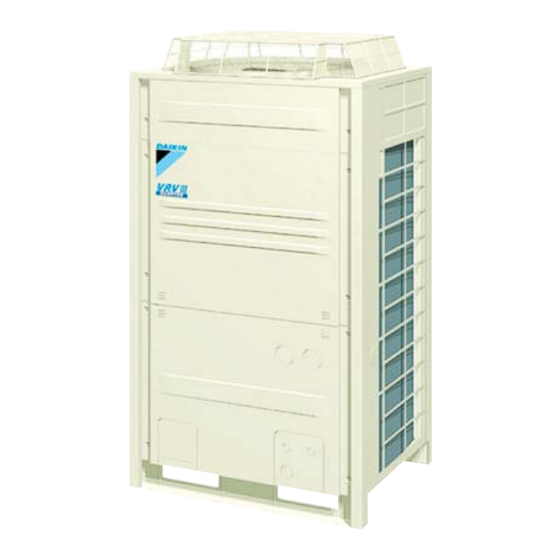
External Appearance SiBE26-701 3. External Appearance Indoor Units Remote Controller Wireless Type Wired Type BRC1D52 Type BRC7 Type Outdoor Units RZQ200C RZQ250C General Information... -
Page 18: Part 2 Specifications
SiBE26-701 Part 2 Specifications Specifications ..................8 Outdoor Units ...................8 2. Electric Characteristics................9 Specifications... -
Page 19: Specifications
Specifications SiBE26-701 1. Specifications Outdoor Units Heat Pump 50Hz Series <RZQ-C> Model RZQ200C7Y1B RZQ250C7Y1B Power Supply 3 phase 50Hz 380~415V ★ 1 Cooling Capacity 20.0 24.1 ★ 2 Heating Capacity 23.0 26.4 Casing Color Ivory White (5Y7.5/1), E type: Light Camel (2.5Y6.5/1.5) Dimensions: (H×W×D) 1,680×930×765 Heat Exchanger... -
Page 20: Electric Characteristics
SiBE26-701 Electric Characteristics 2. Electric Characteristics Unit combination Power supply Comp Indoor Outdoor Hz-Volts Voltage range TOCA FCQ50C7VEB ×4 RZQ200C7Y1B 50-400 16.6 18.6 — 14.7 0.75 0.056×4 0.3×4 FCQ60C7VEB ×3 RZQ200C7Y1B 50-400 16.6 18.6 — 14.7 0.75 0.056×3 0.4×3 FCQ71C7VEB ×3 RZQ200C7Y1B 50-400 16.9... - Page 21 Electric Characteristics SiBE26-701 Specifications...
-
Page 22: Part 3 Remote Controller
SiBE26-701 Part 3 Remote Controller Wired Remote Controller...............12 1.1 Features ....................12 1.2 Installation ....................14 Wireless Remote Controller ..............16 2.1 Features ....................16 3. Method of Operating Remote Controller ..........18 3.1 The INSPECTION / TEST Button............18 Maintenance Mode Setting..............19 3.3 Operation of the Remote Controller’s Inspection / Test Operation Button ................21 3.4 Remote Controller Service Mode ............22 Remote Controller... -
Page 23: Wired Remote Controller
Wired Remote Controller SiBE26-701 1. Wired Remote Controller Features BRC1D52 Type 23 7 1. ON/OFF BUTTON Press the ON/OFF button to start or stop the system. 2. OPERATION LAMP The operation lamp lights up during operation or blinks if a malfunction occurs. 3. - Page 24 SiBE26-701 Wired Remote Controller 12.MAXIMUM SET TEMPERATURE The maximum set temperature indicates the maximum set temperature when in limit operation. 13.MINIMUM SET TEMPERATURE The minimum set temperature indicates the minimum set temperature when in limit operation. 14.SCHEDULE TIMER ICON This icon indicates that the schedule timer is enabled. 15.ACTION ICONS These icons indicate the actions for each day of the schedule timer.
-
Page 25: Installation
Wired Remote Controller SiBE26-701 Installation Remote Controller... - Page 26 SiBE26-701 Wired Remote Controller Remote Controller...
-
Page 27: Wireless Remote Controller
Wireless Remote Controller SiBE26-701 2. Wireless Remote Controller Features Names and Function Model Series Name of Option FCQ-C FFQ-B FHQ-BU FAQ71B FAQ100B H / P BRC7F532F BRC7E530W BRC7E63W BRC7E618 BRC7C510W Remote Controller ON OFF DOWN ON OFF TEMP TIME DOWN RESERVE CANCEL TIMER TEST... - Page 28 SiBE26-701 Wireless Remote Controller TIMER RESERVE/CANCEL BUTTON DISPLAY “ ” (SIGNAL TRANSMISSION) This lights up when a signal is being AIR FLOW DIRECTION ADJUST transmitted. BUTTON DISPLAY “ ” “ ” “ ” “ ” OPERATION MODE SELECTOR “ ” (OPERATION MODE) BUTTON This display shows the current OPER- Press this button to select OPERATION...
-
Page 29: Method Of Operating Remote Controller
Method of Operating Remote Controller SiBE26-701 3. Method of Operating Remote Controller The INSPECTION / TEST Button The following modes can be selected by using the [Inspection/Test Operation] button on the remote control. Depress Inspection/Test Operation button for more than 4 seconds. Indoor unit settings can be made Service data can be obtained. -
Page 30: Maintenance Mode Setting
SiBE26-701 Method of Operating Remote Controller Maintenance Mode Setting 3.2.1 Service Data Confirmation Procedure 1, 2, 7 1. Enter the field set mode. Continue to push the inspection / test operation button for a minimum of 4 seconds. 2. Enter the service mode. After having entered the field set mode, continue to push the inspection / test operation button for a minimum of 4 seconds. - Page 31 Method of Operating Remote Controller SiBE26-701 3.2.2 Service Mode Setting Procedure 1, 2, 6 1. Enter the field set mode. Continue to push the inspection / test operation button for a minimum of 4 seconds. 2. Enter the maintenance mode. After having entered the field set mode, continue to push the inspection / test operation button for a minimum of 4 seconds.
-
Page 32: Operation Of The Remote Controller's Inspection / Test Operation Button
SiBE26-701 Method of Operating Remote Controller Operation of the Remote Controller’s Inspection / Test Operation Button Unit Malfunction code Inspection Normal display (No display) Malfunction code blinks when a malfunction occurs. Inspection/test Push the button. operation Unit 0 7 1... Capacity code Malfunction code F... -
Page 33: Remote Controller Service Mode
Method of Operating Remote Controller SiBE26-701 Remote Controller Service Mode How to Enter the The operation of the Inspection/Test Operation button on the remote controller allows the unit to enter the Test Operation mode. Service Mode When the Start/Stop button is pushed after the Test Operation mode is set, test operation starts. ("Test Operation"... -
Page 34: Part 4 Field Setting
SiBE26-701 Part 4 Field Setting 1. Field Setting of Indoor Unit..............24 1.1 Field Setting from Remote Controller .............24 1.2 Setting Contents and Code No. – SkyAir Indoor Unit ......26 1.3 Detailed Explanation of Setting Modes ..........27 2. Field Setting of Outdoor Unit..............32 2.1 Field Setting from Remote Controller .............32 2.2 Field Setting by Demand Adapter ............35 2.3 Field Setting from Outdoor Unit PC Board ..........38... -
Page 35: Field Setting Of Indoor Unit
Field Setting of Indoor Unit SiBE26-701 1. Field Setting of Indoor Unit Field Setting from Remote Controller Individual function of indoor unit can be changed from the remote controller. At the time of installation or after service inspection / repair, make the local setting in accordance with the following description. - Page 36 SiBE26-701 Field Setting of Indoor Unit 1.1.2 Wireless Remote Controller - Indoor Unit BRC7 type 1. When in the normal mode, push the “ ” button for 4 seconds or more, and operation then enters the “field set mode”. 2. Select the desired “mode No.” with the “ ”...
-
Page 37: Setting Contents And Code No. - Skyair Indoor Unit
Field Setting of Indoor Unit SiBE26-701 Setting Contents and Code No. – SkyAir Indoor Unit Indoor Mode Setting Setting Contents Second Code No.(Note 3) Switch unit settings Note 2 10(20) Filter contamination heavy/ Super Light Approx. Heavy Approx. — — light (Setting for display long life 10,000... -
Page 38: Detailed Explanation Of Setting Modes
SiBE26-701 Field Setting of Indoor Unit Detailed Explanation of Setting Modes 1.3.1 Filter Sign Setting If switching the filter sign ON time, set as given in the table below. Set Time Mode No. First Second Filter Specs. Setting Code No. Code No. -
Page 39: Fan Speed Off When Thermostat Is Off
Field Setting of Indoor Unit SiBE26-701 1.3.5 Setting of the Number of Units for Multi-Unit Simultaneous Operation When using multi-unit simultaneous operation, change the Second Code No. according to the number of units connected as shown in the following table. The factory setting for the Second Code No. -
Page 40: Automatic Operation Mode Control
SiBE26-701 Field Setting of Indoor Unit 1.3.8 Automatic Operation Mode Control Selection of the "Automatic Operation Mode" with a remote controller prevents excessive cooling and heating and offers the most comfortable air temperatures. · Outdoor air temperature The ideal target indoor temperature is ·... -
Page 41: Air Flow Direction Setting
Field Setting of Indoor Unit SiBE26-701 1.3.12 Air Flow Adjustment - Ceiling Height Make the following setting according to the ceiling height. The setting position No. is set to “01” at the factory. In the Case of FHQ, FAQ Setting Switch Setting Position Mode No. - Page 42 SiBE26-701 Field Setting of Indoor Unit 1.3.15 Setting of Air Flow Direction Adjustment Range Make the following air flow direction setting according to the respective purpose. Setting Table Mode No. First Code No. Second Code No. Setting Upward (Draft prevention) 13 (23) Standard Downward (Ceiling...
-
Page 43: Field Setting Of Outdoor Unit
Field Setting of Outdoor Unit SiBE26-701 2. Field Setting of Outdoor Unit Field Setting from Remote Controller 2.1.1 Remote Controller Settings Field setting, which was conventionally done only from outdoor units, can be partly performed from a remote controller. The setting procedure is same as that for indoor unit. The table below contains the remote controller settings. -
Page 44: Explanation Of Each Setting
SiBE26-701 Field Setting of Outdoor Unit 2.1.3 Explanation of Each Setting Nighttime low noise setting This setting is selected when automatic low noise operation is desired during nighttime. There are three levels for low noise operation and "low noise level 3" is the quietest. Furthermore, start/end time of low noise operation can be set and changed. - Page 45 Field Setting of Outdoor Unit SiBE26-701 2.1.4 In Case of Flat Installation For flat installation where an indoor unit and an outdoor unit are installed with a difference in elevation of less than 5 m, use this setting. An energy-saving effect is prominent during low cooling operation with outside air (partial load operation).
-
Page 46: Field Setting By Demand Adapter
SiBE26-701 Field Setting of Outdoor Unit Field Setting by Demand Adapter A demand adapter (optional: KRP58M2) is used to make the following setting for outdoor units. 1) Setting of demand operation by external input 2) Setting of low noise operation by external input Parts and Function DS1, X81A and X800M cannot be used for RZQ200 and 250C models. - Page 47 Field Setting of Outdoor Unit SiBE26-701 Setting Procedure 1. Connect the demand adapter X80A to X36A and X66A on the outdoor unit control PCB. 2. According to the desired demand, short-circuit between the terminals on the demand adapter terminal block X801M. Setting procedure Terminal block X801M Demand 1...
- Page 48 SiBE26-701 Field Setting of Outdoor Unit Image of "Low noise operation" by external input + "Required capacity prior" set by remote controller If capacity precedence is set in "Capacity precedence setting", the fan speed will be increased according to the load of air Operation sound conditioning when load is heavier.
-
Page 49: Field Setting From Outdoor Unit Pc Board
Field Setting of Outdoor Unit SiBE26-701 Field Setting from Outdoor Unit PC Board The operation of BS buttons and DIP switches on the PCB (main PCB: A1P) allows the confirmation and setting of various items. High Night Test 9 ⎫ Static time Low page... - Page 50 SiBE26-701 Field Setting of Outdoor Unit 2.3.2 Setting Mode 1 · 2 Setting by BS buttons With "Setting mode 1" and "Setting mode 2", various settings and data can be checked. Procedure for Changing Setting Mode Using the MODE button, the modes can be changed as follows. MODE MODE Push and hold the BS1 (MODE button) for 5 seconds.
- Page 51 Field Setting of Outdoor Unit SiBE26-701 Change of Setting Conditions in "Setting Mode 2" LED Display Condition setting No. Setting Item Push and hold the MODE (BS1) pattern H1P H2P H3P H4P H5P H6P H79 button for 5 seconds and set to Additional refrigerant charge operation 8 1 1 1 1 1 1 “Setting mode 2”.
- Page 52 SiBE26-701 Field Setting of Outdoor Unit 2.3.3 Detailed Explanation of Setting Mode 2 Additional refrigerant charge operation In case where it is impossible to refill refrigerant when the compressor is stopped, additional refrigerant charge operation is performed. [Work procedure] 1. First, conduct normal charging. Charge refrigerant from the stop valve service port on the liquid side while the outdoor unit is stopped.
- Page 53 Field Setting of Outdoor Unit SiBE26-701 Setting of refrigerant recovery mode When a refrigerant recovery unit is connected on site to recover refrigerant, fully open the expansion valve of the outdoor unit to help the recovery. [Work procedure] 1. Stop operation. 2.
- Page 54 SiBE26-701 Field Setting of Outdoor Unit Defrost Changeover 2 Operation Used to shift the temperature that determines whether or not to enter defrosting operation. Shifted temperature MODE 1 (Factory Setting) — MODE 2 MODE 1+4°C MODE 3 MODE 1+6°C [Work procedure] 1.
-
Page 55: Emergency Operation
Emergency Operation SiBE26-701 3. Emergency Operation There are three methods for emergency operation. Select one that best suits its purpose. Operation Name Purpose Setting procedure Thermistor Protective unit Drain pump Remarks detection actuation Use the SS1 switch on Temperature is not Emergency ×... -
Page 56: Test Operation Setting Procedure
SiBE26-701 Emergency Operation Test Operation Setting Procedure 1. Push the Inspection/Test Operation button on the remote controller 4 times. Push the Inspection/Test Operation button 4 times. Normal mode Test operation mode 2. When the Start/Stop button is pushed after the test operation mode is set, test operation starts. - Page 57 Emergency Operation SiBE26-701 Field Setting...
-
Page 58: Part 5 Function And Operation
SiBE26-701 Part 5 Function and Operation 1. Indoor Unit.....................48 1.1 Function Details..................48 2. Outdoor Unit..................54 2.1 Function List ...................54 2.2 Flow Chart of Outdoor Unit..............55 2.3 Table of Functions and Operations ............57 2.4 Function Details..................61 3. List of Electrical and Functional Parts ...........71 3.1 Outdoor Unit ...................71 4. -
Page 59: Indoor Unit
Indoor Unit SiBE26-701 1. Indoor Unit Function Details 1.1.1 Thermostat Control Purpose Based on the information received from the air return sensor, the thermostat control will decide the required operation status of the system. Thermostat Control Set point Cooling mode: –0.5˚C Thermostat ON +0.5˚C... - Page 60 SiBE26-701 Indoor Unit 1.1.2 Using Conditions for Remote Controller Thermostat Applicable The remote control thermostat is only available in wired remote controls. Method Unlike with VRV units, the remote control sensor is standard disabled for sky-air units. The use of the remote control sensor can be enabled by changing field setting 10(20)-2-02 to 10(20)-2- Conditions The table below contains the condition in which the remote control thermostat is not used: Condition The remote controller thermostat is not used when...
- Page 61 Indoor Unit SiBE26-701 1.1.3 Program Dry Operation Function Function Detail The points of thermostat ON or OFF are determined according to the suction air temperature at the startup of unit operation. The set temperature and flow rate are not displayed on remote controller. Operation startup Thermostat (Differential)
-
Page 62: Drain Pump Control
SiBE26-701 Indoor Unit 1.1.6 Fan Airflow Direction Adjustment Control The control of horizontal (or vertical) fans to adjust airflow is shown in the table below: FAQ71 FAQ100 In Airflow Thermostat ON Setting Setting Setting Direction Thermostat OFF Setting Setting Setting Operation Cooling Thermostat ON... -
Page 63: Dew Condensation Prevention Control
Indoor Unit SiBE26-701 1.1.9 Dew Condensation Prevention Control (FHQ71·100, FAQ71·100) In cooling and dry operation, the following control is carried out in order to prevent dew condensation when the horizontal blade blows air downward. [Start condition] • Horizontal blade is set to downward flow &... -
Page 64: Defrost Control
SiBE26-701 Indoor Unit 1.1.12 Defrost Control If heating operation is continued in low outdoor air temperatures, frost forms on the surface of the outdoor heat exchanger, resulting in a decrease in heating performance. Accordingly, when frost formation reaches a certain level, it automatically switches to cooling cycle for defrosting. When the frost completely melts, normal heating operation resumes. -
Page 65: Outdoor Unit
Outdoor Unit SiBE26-701 2. Outdoor Unit Function List Input Control Outdoor signal Syembol Unit Function Input Item Function control item detail No. Thermistor for Discharge Pipe (*1) Thermistor for Outdoor Air Temperature Malfunction stop 2.4.1 Malfunction stop Thermistor for Heat Exchanger Restart standby 2.4.2.1 Standby... -
Page 66: Flow Chart Of Outdoor Unit
SiBE26-701 Outdoor Unit Flow Chart of Outdoor Unit [Cooling/Dry operation] Note: (Refer to outdoor unit item (X.X.X)) means refer to Outdoor Unit (P. 57 and after) in detailed description of function. Power supply ON Initialize electronic expansion valve Initialize microcomputer Stopping Crank case heater control (refer to outdoor unit item 2.4.2.2) - Page 67 Outdoor Unit SiBE26-701 [Heating operation] Note: (Refer to outdoor unit item X.X.X) means refer to Outdoor Unit (P. 57 and after) in detailed description of function. Power supply ON Initialize electronic expansion valve Initialize microcomputer Stopping Crank case heater control (refer to outdoor unit item 2.4.2.2) Remote controller ON operation Judgement...
-
Page 68: Table Of Functions And Operations
SiBE26-701 Outdoor Unit Table of Functions and Operations 2.3.1 Cooling 1 (Control while Compressor is Stopped) While compressor is stopped "Pressure equalization "Restart standby" Thermostat OFF standby In normal operation control before startup" Compressor 0Hz (*1) 0Hz (*1) OFF (*1) 0Hz (*1) [INV] "Pressure equalization... - Page 69 Outdoor Unit SiBE26-701 2.3.3 Cooling 3 (Pump Down Residual Operation / Oil Return Operation) Compressor in operation "Cooling operation pump down residual operation" "Oil return operation control" Basic operation Protection control Basic operation Protection control "High pressure protection "High pressure protection control"...
- Page 70 SiBE26-701 Outdoor Unit 2.3.5 Heating 2 (Startup Control / Control during Operation) Compressor in operation "Heating startup control In normal operation Basic operation Protection control Basic operation Protection control "Low pressure protection control" "High pressure protection "High pressure protection control" control"...
- Page 71 Outdoor Unit SiBE26-701 2.3.7 Heating 4 (Defrosting Operation) Compressor in operation "Details of defrost control", "Defrost completion judgment control" Basic operation Protection control "Before defrosting "During defrosting" After defrosting (2 minutes)" "Low pressure protection control" "High pressure protection control" "High pressure protection control (cooling)"...
-
Page 72: Function Details
SiBE26-701 Outdoor Unit Function Details 2.4.1 Malfunction Stop (Retry Control) When the following items show abnormal values, the thermostat turns OFF and malfunction is determined based on the number of retry in order to protect the compressor and other devices. Item Criteria Number of retry... -
Page 73: Startup Control
Outdoor Unit SiBE26-701 2.4.3 Startup Control 2.4.3.1 Startup Control When compressor start up, the starting frequency is fixed for specified period of time at low frequency to prevent returning of refrigerant. Pressure equalizing 165Hz+OFF 52Hz+OFF Compressor 0Hz+OFF Electronic expansion valve Equalizer electronic expansion valve... -
Page 74: Function Control
SiBE26-701 Outdoor Unit 2.4.4 Function Control 2.4.4.1 Compressor Step Control In order to control capacity, the compressor operation is controlled according to the following steps: <RZQ200 · 250C> Step No. Comp. operation frequency Step No. Comp. operation frequency 52Hz 143Hz 57Hz 158Hz 62Hz... - Page 75 Outdoor Unit SiBE26-701 2.4.4.4 Hot Start Control (in Heating Operation Only) The indoor unit fan is controlled to prevent cold air flow and secure a starting capacity when starting up heating operation or completing defrosting. Indoor unit fan:OFF Heating operation ON by remote controller ·...
-
Page 76: Protection Control
SiBE26-701 Outdoor Unit 2.4.5 Protection Control 2.4.5.1 Low Pressure Protection Control Drooping control and protection control below mentioned are conducted to prevent low pressure from abnormal lowering. [When cooling operation] [When heating operation] Normal operation Normal operation · Lp<0.19MPa Lp>0.23MPa Lp<0.34 Lp>0.38MPa &... -
Page 77: Pump Down Residual Operation
Outdoor Unit SiBE26-701 2.4.5.3 Heating Operation High Outdoor Air Temperature Control Under heating overload conditions, the outdoor unit fan is controlled to protect the compressor. Normal Operation · · Hp-Lp<0.4MPa · Hp-Lp>0.8MPa · · · & Compression ratio <1.8 Compression ratio >2.6 &... - Page 78 SiBE26-701 Outdoor Unit 2.4.5.6 Cooling Operation Low Outdoor Air Temperature Control Under low outdoor air temperature conditions during cooling operation, the outdoor unit fan is controlled to maintain high pressure and secure refrigerant flow. Normal operation · · Hp-Lp<1.3MPa · Hp-Lp>1.7MPa ·...
-
Page 79: Defrosting Operation
Outdoor Unit SiBE26-701 2.4.5.9 Suction Pipe Superheat Protection Control (in Heating Operation Only) In heating operation, controls compressor operating frequency to prevent oil from remaining in the outdoor unit heat exchanger by the continuous operation of compressor at high superheated degree of the suction pipe. - Page 80 SiBE26-701 Outdoor Unit Max. Integral Capacity Value Diminishing Integral Capacity Compressor Running Time Heating Defrosting Defrost activation temperature Using field setting switches (see P69), the temperature to activate defrosting can be shifted as follows: Evaporating + 6ºC Temperature(ºC) Outside air (Mode 3) temperature (ºC) + 4ºC...
- Page 81 Outdoor Unit SiBE26-701 2.4.7 Servicing Function 2.4.7.1 Emergency Operation No transmission between outdoor and indoor units available A cycle of a 20-minute operation and a 10-minute stop is repeated in cooling operation. Defrosting operation is performed once in 1 hour in heating operation. Other controls are same as those performed in normal operation.
-
Page 82: List Of Electrical And Functional Parts
SiBE26-701 List of Electrical and Functional Parts 3. List of Electrical and Functional Parts Outdoor Unit RZQ200 · 250C7Y1B Model Item Name Symbol RZQ200C7Y1B RZQ250C7Y1B Type JT1GCVDKR@T Inverter OC protection 14.7A device Output 0.75kW Fan motor OC protection device For main EC0676 For noise filrer FN354-H-1... -
Page 83: Operation Range
Operation Range SiBE26-701 4. Operation Range Operation Limits 4TW26566 Function and Operation... -
Page 84: Part 6 Troubleshooting
SiBE26-701 Part 6 Troubleshooting 1. Maintenance Inspections ..............75 1.1 Optimal Operation Condition ..............75 1.2 Refrigerant Saturation Curve (R-410A) ..........78 1.3 Cautions in Handling New Refrigerant ...........79 2. Troubleshooting Based on Equipment Condition........83 2.1 Troubleshooting Based on Equipment Condition ........83 2.2 Equipment does not Operate ..............84 2.3 Indoor Fan Operates, but Compressor does not........85 2.4 Cooling/Heating Operation Starts but Stops Immediately ......87 2.5 After Equipment Shuts Down, It cannot be Restarted for a While..89... - Page 85 SiBE26-701 4.26 “JC” Malfunction of Low Pressure Sensor ..........140 4.27 “L1” Faulty Outdoor Inverter PC board ..........142 4.28 “L4” Radiation Fin Temperature Increased ...........143 4.29 “L5” Momentary Overcurrent of Inverter Compressor ......145 4.30 “L8” Inverter Compressor Overcurrent ..........147 4.31 “L9” Compressor Inverter Start up Error ..........149 4.32 “LC”...
-
Page 86: Maintenance Inspections
SiBE26-701 Maintenance Inspections 1. Maintenance Inspections Optimal Operation Condition Guide Lines for The operation value guide lines when operating under standard conditions (at Rated frequency) by pushing the test run button on the remote controller are as given in the table Optimal below. - Page 87 Maintenance Inspections SiBE26-701 Correlation of Air- What happens in comparison to normal values is summarized in the table below. (Measured from 15 ~ 20 minutes or more after operation starts.) Conditioner’s Operation Status and Pressure / When Cooling Running Current Air-Conditioner Status Low Pressure High Pressure...
- Page 88 SiBE26-701 Maintenance Inspections Items Key points Items Key points Power Inverter To replace the PC board assembly with Instantaneo- Insufficient voltage and instantaneous supply service parts, follow the procedure shown us power power failure resulted in an operation section and board below.
-
Page 89: Refrigerant Saturation Curve (R-410A)
Maintenance Inspections SiBE26-701 Refrigerant Saturation Curve (R-410A) 4.00 3.90 3.70 3.80 3.60 3.50 3.40 3.30 3.20 3.10 3.00 2.90 2.70 2.80 2.60 2.50 2.40 2.30 2.20 2.10 2.00 1.90 1.70 1.80 1.60 1.50 1.40 1.30 1.20 1.10 1.00 0.90 0.70 0.80 0.60 0.50... -
Page 90: Cautions In Handling New Refrigerant
SiBE26-701 Maintenance Inspections Cautions in Handling New Refrigerant 1.3.1 Refrigerant and Refrigerant Oil While the performance of refrigerant R-410A is almost equivalent to that of refrigerant R-22 and R-407C, its working pressure is approximately 1.4 times higher than them. Therefore, servicing and tools necessary for piping of them are different. - Page 91 Maintenance Inspections SiBE26-701 1.3.3 Piping Connection Since stricter prevention of impurity incorporation is required for new refrigerant, be sure to blow nitrogen during brazing work. In addition to brazing, pipe curing and vacuum drying must be surely performed in order to prevent impurity incorporation into the piping system and at the same time more complete construction management must be carried out.
-
Page 92: Refrigerant Charge
SiBE26-701 Maintenance Inspections 1.3.4 Flaring and Flare Nut Precautions for flaring Ensure chamfering (filing). Furthermore, pay utmost care not to leave chips inside of piping. Apply an appropriate coating of refrigeration machine oil to the inner and outer surfaces of the flare nut to prevent any leaks. -
Page 93: Air Tighteness Test
Maintenance Inspections SiBE26-701 1.3.6 Air Tighteness Test Refrigerant Recovery Method Before replacing parts of the refrigerant system, be sure to collect refrigerant. The refrigerant recovery procedure is as follows: RZQ200 • 250C [Refrigerant recovery procedure] (1) Stop operation. (2) Confirm that both of liquid side stop valve and gas side stop valve are fully open. →... -
Page 94: Troubleshooting Based On Equipment Condition
SiBE26-701 Troubleshooting Based on Equipment Condition 2. Troubleshooting Based on Equipment Condition Troubleshooting Based on Equipment Condition Equipment Condition Remedy Equipment does not operate. See 84 Fan operates, but compressor does not. See 85 Cooling/heating operation starts but stops See 87 immediately. -
Page 95: Equipment Does Not Operate
Troubleshooting Based on Equipment Condition SiBE26-701 Equipment does not Operate Applicable Model All models of SkyAir series Error Detection Method Error Generating Condition Possible Causes Fuse blown or disorder of contact in operation circuit Faulty operation switch or contact point Faulty high pressure switch Faulty magnetic switch for fan motor Activation or fault of overcurrent relay for fan motor... -
Page 96: Indoor Fan Operates, But Compressor Does Not
SiBE26-701 Troubleshooting Based on Equipment Condition Indoor Fan Operates, but Compressor does not Applicable Model All models of SkyAir series Method of Malfunction Detection Malfunction Decision Conditions Possible Causes Faulty thermistor Faulty indoor/outdoor unit PC board Faulty magnetic switch Faulty power transistor Faulty compressor Troubleshooting... - Page 97 Troubleshooting Based on Equipment Condition SiBE26-701 Troubleshooting Be sure to turn off power switch before connect or disconnect connector, Caution or parts damage may be occurred. · Indoor unit fan runs at set airflow rate. · (In cooling operation) When air thermistor ambient temperature is higher than set temperature ·...
-
Page 98: Cooling/Heating Operation Starts But Stops Immediately
SiBE26-701 Troubleshooting Based on Equipment Condition Cooling/Heating Operation Starts but Stops Immediately Applicable Model All models of SkyAir series Error Detection Method Error Generating Condition Possible Cause Excess charge of refrigerant Air intrudes into refrigerant system Faulty pressure switch Faulty magnetic switch for outdoor unit fan motor Faulty aux. - Page 99 Troubleshooting Based on Equipment Condition SiBE26-701 Troubleshooting Be sure to turn off power switch before connect or disconnect connector, Caution or parts damage may be occurred. Is the type of wired the operation Diagnose based on the remote controller wired or lamp of remote controller wireless? flashing?
-
Page 100: After Equipment Shuts Down, It Cannot Be Restarted For A While
SiBE26-701 Troubleshooting Based on Equipment Condition After Equipment Shuts Down, It cannot be Restarted for a While Applicable Model All models of SkyAir series Error Detection Method Error Generating Condition Possible Cause Overcurrent relay (for compressor) Compressor protection thermostat Overcurrent relay may act due to the following reasons Lower voltage of power supply Excess level of high pressure Insufficient size of power cable... -
Page 101: Equipment Operates But Does Not Provide Cooling
Troubleshooting Based on Equipment Condition SiBE26-701 Equipment Operates but does not Provide Cooling Applicable Model All models of SkyAir series Error Detection Method Error Generating Condition Possible Cause Overcurrent relay (for compressor) Compressor protection thermostat Overcurrent relay (for compressor) may act due to the following reasons Lower voltage of power supply Excess level of high pressure Insufficient size of power cable... - Page 102 SiBE26-701 Troubleshooting Based on Equipment Condition Troubleshooting Be sure to turn off power switch before connect or disconnect connector, Caution or parts damage may be occurred. Measure the temperature of suction air and supply air. Temperature difference = Suction air temp. – Supply air temp.
-
Page 103: Equipment Operates But Does Not Provide Heating
Troubleshooting Based on Equipment Condition SiBE26-701 Equipment Operates but does not Provide Heating Applicable Model All models of SkyAir series Error Detection Method Error Generating Condition Possible Cause Excess charge of refrigerant Air intrudes into refrigerant system Faulty pressure switch Faulty magnetic switch for outdoor unit fan motor Faulty aux. -
Page 104: Equipment Discharges White Mist
SiBE26-701 Troubleshooting Based on Equipment Condition Equipment Discharges White Mist Applicable Model All models of SkyAir series Error Detection Method Error Generating Condition Possible Cause Humid installation site Installation site is dirty and with dense oil mists. Soiled heat exchanger Clogged air filter Malfunction of fan motor Troubleshooting... -
Page 105: Equipment Produces Loud Noise Or Shakes
Troubleshooting Based on Equipment Condition SiBE26-701 Equipment Produces Loud Noise or Shakes Applicable Model All models of SkyAir series Error Detection Method Error Generating Condition Possible Cause Faulty installation Excess charge of refrigerant Air intrudes into refrigerant system Flushing noise due to refrigerant shortage. (Sound of shoo...) Troubleshooting Be sure to turn off power switch before connect or disconnect connector, Caution... -
Page 106: Equipment Discharges Dust
SiBE26-701 Troubleshooting Based on Equipment Condition 2.10 Equipment Discharges Dust Applicable Model All models of SkyAir series Error Detection Method Error Generating Condition Possible Cause Carpet spread room Animal's hair Troubleshooting Be sure to turn off power switch before connect or disconnect connector, Caution or parts damage may be occurred. -
Page 107: Remote Controller Lcd Displays "88
Troubleshooting Based on Equipment Condition SiBE26-701 2.11 Remote Controller LCD Displays "88" Applicable Model All models of SkyAir series Error Detection Method Error Generating Condition Possible Cause Troubleshooting Be sure to turn off power switch before connect or disconnect connector, Caution or parts damage may be occurred. -
Page 108: Swing Flap Does Not Move
SiBE26-701 Troubleshooting Based on Equipment Condition 2.12 Swing Flap does not Move Applicable FAQ, FBQ, FHQ, FUQ Models Error Detection Use the limit switch that turns ON and OFF according to the motor rotation. Method Error Generating When ON and OFF of the micro-switch for positioning control cannot be switched even when the motor for regulating airflow direction is powered for a certain period of time (approx. -
Page 109: Procedure Of Self-Diagnosis By Led
Procedure of Self-Diagnosis by LED SiBE26-701 3. Procedure of Self-Diagnosis by LED Troubleshooting by LED on Outdoor Unit PC Board The following diagnosis can be conducted by turning on the power switch and checking the LED indication on the printed circuit board of the outdoor unit. : LED on : LED off : LED blinks... -
Page 110: Diagnosis By Remote Controller
SiBE26-701 Diagnosis by Remote Controller 4. Diagnosis by Remote Controller Confirm Method of Malfunction Code 4.1.1 Self-diagnosis by Wired Remote Controller Explanation If operation stops due to malfunction, the remote controller’s operation LED blinks, and malfunction code is displayed. (Even if stop operation is carried out, malfunction contents are displayed when the inspection mode is entered.) The malfunction code enables you to tell what kind of malfunction caused operation to stop. - Page 111 Diagnosis by Remote Controller SiBE26-701 4.1.2 Self-Diagnosis by Wireless Remote Controller If equipment stops due to a malfunction, the operation indicating LED on the light reception section flashes. The malfunction code can be determined by following the procedure described below. (The malfunction code is displayed when an operation error has occurred.
- Page 112 SiBE26-701 Diagnosis by Remote Controller Troubleshooting...
-
Page 113: Remote Controller Display Malfunction Code And Contents
Diagnosis by Remote Controller SiBE26-701 Remote Controller Display Malfunction Code and Contents Malfunction Code Contents/Processing Remarks Failure of PC board ass’y for indoor unit Malfunction of drain water level system Indoor unit fan motor overload / overcurrent / lock Malfunction of swing flap motor Abnormal drain water level Activation of float switch during compressor off. - Page 114 SiBE26-701 Diagnosis by Remote Controller Malfunction Code Contents/Processing Remarks Open phase or voltage unbalance Failure of capacity setting (outdoor unit) Either capacity data is set incorrectly, or capacity has not been set for the data IC Lack of refrigerant malfunction (low level) Lack of refrigerant malfunction (high level) Reverse phase power supply Abnormal power supply voltage...
-
Page 115: A1" Failure Of Indoor Unit Pc Board
Diagnosis by Remote Controller SiBE26-701 “A1” Failure of Indoor Unit PC Board Remote Controller Display Applicable All indoor unit models Models Method of Check data from E²PROM. Malfunction Detection Malfunction When data could not be correctly received from the E²PROM E²PROM : Type of nonvolatile memory. -
Page 116: A3" Malfunction Of Drain Water Level System (Float Type)
SiBE26-701 Diagnosis by Remote Controller “A3” Malfunction of Drain Water Level System (Float Type) Remote Controller Display Applicable FCQ, FBQ, FDQ, FFQ, FHQ, FUQ Models Method of By float switch OFF detection Malfunction Detection Malfunction When rise of water level is not a condition and the float switch goes OFF. Decision Conditions Supposed... - Page 117 Diagnosis by Remote Controller SiBE26-701 Troubleshooting Be sure to turn off power switch before connect or disconnect connector, Caution or parts damage may be occurred. If “A3” is detected by a PC board which is not mounted with X15A, FHQ? the PC board is defective.
-
Page 118: A6" Malfunction Of Indoor Unit Fan Motor
SiBE26-701 Diagnosis by Remote Controller “A6” Malfunction of Indoor Unit Fan Motor Remote Controller Display Applicable FCQ, FAQ Models Method of Detection of abnormal fan speed by signal from the fan motor Malfunction Detection Malfunction When fan speed does not increase Decision Conditions Supposed... - Page 119 Diagnosis by Remote Controller SiBE26-701 Troubleshooting Be sure to turn off power switch before connect or disconnect connector, Caution or parts damage may be occurred. Turn off the power supply. Wait for 10min. Is there any foreign matter Remove the foreign matter. around the fan? Is the harness from the...
-
Page 120: A6" Malfunction Of Indoor Unit Fan Motor
SiBE26-701 Diagnosis by Remote Controller “A6” Malfunction of Indoor Unit Fan Motor Remote Controller Display Applicable FAQ100, FHQ Models Method of To be detected based on transmission failure of the signal by the fan motor for detecting the Malfunction number of rotation Detection Malfunction When number of rotation can not be detected even at the maximum output voltage to the fan... -
Page 121: A6" Indoor Unit Fan Motor Overload, Overcurrent, Lock
Diagnosis by Remote Controller SiBE26-701 “A6” Indoor Unit Fan Motor Overload, Overcurrent, Lock Remote Controller Display Applicable FDQ200 · 250 Models Method of Detect the status in which the separate power supply for the fan is cut OFF. Malfunction Detection Malfunction Unable to detect that separate power supply for the indoor unit fan is turned ON. - Page 122 SiBE26-701 Diagnosis by Remote Controller Troubleshooting Be sure to turn off power switch before connect or disconnect connector, Caution or parts damage may be occurred. Is the power supply for the Connect correctly. indoor fan correctly connected? Is the fan interlock PC Connect correctly.
-
Page 123: A7" Malfunction Of Swing Flap Motor
Diagnosis by Remote Controller SiBE26-701 “A7” Malfunction of Swing Flap Motor Remote Controller Display Applicable FAQ100, FCQ, FBQ, FHQ, FUQ Models Method of Make use of the limit switch turning ON/ OFF according to rotation of the motor. Malfunction Detection Malfunction When supplying power to the swing motor for a certain length (approx. -
Page 124: Af" Failure Of Drain System
SiBE26-701 Diagnosis by Remote Controller “AF” Failure of Drain System Remote Controller Display Applicable FCQ, FBQ, FDQ, FFQ, FUQ Models Method of Water leakage is detected based on float switch ON/OFF operation while the compressor is in Malfunction non-operation. Detection Malfunction When the float switch changes from ON to OFF while the compressor is in non-operation. -
Page 125: Aj" Malfunction Of Capacity Determination Device
Diagnosis by Remote Controller SiBE26-701 4.10 “AJ” Malfunction of Capacity Determination Device Remote controller display Applicable FAQ, FCQ, FFQ, FHQ, FUQ Models Method of Capacity is determined according to resistance of the capacity setting adaptor and the memory inside the IC memory on the indoor unit PC board, and whether the value is normal or abnormal Malfunction is determined. -
Page 126: C4" Malfunction Of Heat Exchange Temperature Sensor System
SiBE26-701 Diagnosis by Remote Controller 4.11 “C4” Malfunction of Heat Exchange Temperature Sensor System Remote Controller Display Applicable All indoor unit models Models Method of Malfunction detection is carried out by temperature detected by heat exchanger sensor. Malfunction Detection Malfunction When the heat exchanger thermistor becomes disconnected or shorted while the unit is running. -
Page 127: C9" Malfunction Of Suction Air Temperature Sensor System
Diagnosis by Remote Controller SiBE26-701 4.12 “C9” Malfunction of Suction Air Temperature Sensor System Remote Controller Display Applicable All indoor unit models Models Method of Malfunction detection is carried out by temperature detected by suction air temperature sensor. Malfunction Detection Malfunction When the suction air temperature sensor’s thermistor becomes disconnected or shorted while Decision... -
Page 128: Cc" Malfunction Of Humidity Sensor System
SiBE26-701 Diagnosis by Remote Controller 4.13 “CC” Malfunction of Humidity Sensor System Remote Controller Display Applicable Models Method of Even if a malfunction occurs, operation still continues. Malfunction is detected according to the moisture (output voltage) detected by the moisture Malfunction sensor. -
Page 129: Cj" Malfunction Of Remote Controller Air Thermistor
Diagnosis by Remote Controller SiBE26-701 4.14 “CJ” Malfunction of Remote Controller Air Thermistor Remote Controller Display Applicable All indoor unit models Models Method of Even if remote controller thermistor is faulty, system is possible to operate by system thermistor. Malfunction detection is carried out by temperature detected by remote controller thermistor. Malfunction Detection Malfunction... -
Page 130: E1" Failure Of Outdoor Unit Pc Board
SiBE26-701 Diagnosis by Remote Controller 4.15 “E1” Failure of Outdoor Unit PC Board Remote Controller Display Applicable Models Method of Microcomputer checks whether E PROM is normal. Malfunction Detection Malfunction PROM: When E PROM malfunctions when turning the power supply on Decision Conditions Supposed... -
Page 131: E3" Abnormal High Pressure Level
Diagnosis by Remote Controller SiBE26-701 4.16 “E3” Abnormal High Pressure Level Remote Controller Display Applicable Models Method of Detect continuity of high-pressure switch via protection device circuit Malfunction Detection Malfunction When the high pressure switch is actuated Actuating pressure: 4.0MPa Decision Conditions Supposed... - Page 132 SiBE26-701 Diagnosis by Remote Controller Troubleshooting Be sure to turn off power switch before connect or disconnect connector, Caution or parts damage may be occurred. Is the stop Open the stop valve. valve open? control and protection HPS connected to Connect correctly.
-
Page 133: E4" Low Pressure System Malfunction
Diagnosis by Remote Controller SiBE26-701 4.17 “E4” Low Pressure System Malfunction Remote Controller Display Applicable Models Method of Detect malfunctions by the low pressure sensor (S1NPL). Malfunction Detection Malfunction When the detection pressure is the following value Actuating pressure: 0.07MPa Decision Conditions Supposed... - Page 134 SiBE26-701 Diagnosis by Remote Controller Troubleshooting Be sure to turn off power switch before connect or disconnect connector, Caution or parts damage may be occurred. Check the installation conditions Is the stop valve Open the stop valve. open? Is the connector (*1) for the low-pressure Connect correctry.
-
Page 135: E5" Inverter Compressor Motor Lock
Diagnosis by Remote Controller SiBE26-701 4.18 “E5” Inverter Compressor Motor Lock Remote Controller Display Applicable Models Method of Detect the motor lock when the compressor is energized. Malfunction Detection Malfunction If the motor rotor does not rotate when the compressor is energized. Decision Conditions Supposed... -
Page 136: E7" Malfunction Of Outdoor Unit Fan Motor
SiBE26-701 Diagnosis by Remote Controller 4.19 “E7” Malfunction of Outdoor Unit Fan Motor Remote Controller Display Applicable Models Method of Abnormality of fan motor system is detected according to the fan speed detected by hall IC Malfunction when the fan motor runs. Detection Malfunction When the fan runs with speed less than a specified one for 6 seconds or more... - Page 137 Diagnosis by Remote Controller SiBE26-701 Troubleshooting Be sure to turn off power switch before connect or disconnect connector, Caution or parts damage may be occurred. Cut the power supply to wait for 10 minutes. There is a foreign substance Remove the foreign found around the substance.
- Page 138 SiBE26-701 Diagnosis by Remote Controller No continuity on the fan inverter Replace the fan inverter PC board PC board fuse (FIU) Unable to rotate the fan manually with ease when Replace the corresponding fan motor removing the connector of the fan motor resistance value between the...
-
Page 139: E9" Malfunction Of Moving Part Of Electronic Expansion Valve
Diagnosis by Remote Controller SiBE26-701 4.20 “E9” Malfunction of Moving Part of Electronic Expansion Valve Remote Controller Display Applicable Models Method of Check disconnection of connector Check continuity of expansion valve coil Malfunction Detection Malfunction Error is generated under no common power supply when the power is on. Decision Conditions Supposed... - Page 140 SiBE26-701 Diagnosis by Remote Controller Troubleshooting Be sure to turn off power switch before connect or disconnect connector, Caution or parts damage may be occurred. Turn power supply off, and turn power supply on again. Return to normal? External factor other than malfunction (for example, noise etc.).
-
Page 141: F3" Malfunction Of Discharge Pipe Temperature
Diagnosis by Remote Controller SiBE26-701 4.21 “F3” Malfunction of Discharge Pipe Temperature Remote Controller Display Applicable Models Method of Abnormality is detected according to the temperature detected by the discharge pipe Malfunction temperature sensor. Detection Malfunction When the discharge pipe temperature rises to an abnormally high level (115°C) When the discharge pipe temperature rises suddenly Decision After operation start, the discharge pipe temperature dose not rise. - Page 142 SiBE26-701 Diagnosis by Remote Controller Troubleshooting Be sure to turn off power switch before connect or disconnect connector, Caution or parts damage may be occurred. Is the discharge pipe Abnormality in refrigerant temperature high? (See *1.) system such as gas shortage, faulty compressor, etc.
-
Page 143: H3" Abnormal High Pressure Switch
Diagnosis by Remote Controller SiBE26-701 4.22 “H3” Abnormal High Pressure Switch Remote Controller Display Applicable Models Method of Detect the continuity of the high pressure switch via protection device circuit. Malfunction Detection Malfunction No continuity is detected at the high pressure switch during operation stop of the compressor. Decision Conditions Supposed... - Page 144 SiBE26-701 Diagnosis by Remote Controller Troubleshooting Be sure to turn off power switch before connect or disconnect connector, Caution or parts damage may be occurred. Is the connector of the high-pressure switch correctly Connect correctly. connected to the outdoor unit PC board? (∗1) Check the next procedure 10 minutes after the...
-
Page 145: H7" Abnormal Outdoor Fan Motor Signal
Diagnosis by Remote Controller SiBE26-701 4.23 “H7” Abnormal Outdoor Fan Motor Signal Remote Controller Display Applicable Models Method of Detection of abnormal signal from fan motor. Malfunction Detection Malfunction In case of detection of abnormal signal at starting fan motor. Decision Conditions Supposed... - Page 146 SiBE26-701 Diagnosis by Remote Controller Troubleshooting Be sure to turn off power switch before connect or disconnect connector, Caution or parts damage may be occurred. Turn power off. Is the connector of the fan motor correctly connected? Connect correctly. (∗1) Check the connector of the fan motor (X2A) (Refer to ∗2) Is each...
-
Page 147: H9" "J3" "J5" "J6" "J7" "J8" Malfunction Of Thermistor System
Diagnosis by Remote Controller SiBE26-701 4.24 “H9” “J3” “J5” “J6” “J7” “J8” Malfunction of Thermistor System H9,J3,J5,J6, J7, J8 Remote Controller Display Applicable Models Method of Abnormality is detected according to the temperature detected by each individual thermistor. Malfunction Detection Malfunction When thermistor is disconnected or short-circuited during operation Decision... - Page 148 SiBE26-701 Diagnosis by Remote Controller Troubleshooting Be sure to turn off power switch before connect or disconnect connector, Caution or parts damage may be occurred. Check connectors for connection.∗1 Normal? Connect correctly. ∗2 Remove thermistor from outdoor unit PC board, then measure the resistance using a tester.
-
Page 149: Ja" Malfunction Of High Pressure Sensor
Diagnosis by Remote Controller SiBE26-701 4.25 “JA” Malfunction of High Pressure Sensor Remote Controller Display Applicable Models Method of Malfunction is detected from the pressure detected by the high pressure sensor. Malfunction Detection Malfunction When the high pressure sensor is short circuit or open circuit. Decision Conditions Supposed... - Page 150 SiBE26-701 Diagnosis by Remote Controller Troubleshooting Be sure to turn off power switch before connect or disconnect connector, Caution or parts damage may be occurred. The high pressure sensor is connected to X32A of Connect the high pressure sensor outdoor unit PC and turn on again.
-
Page 151: Jc" Malfunction Of Low Pressure Sensor
Diagnosis by Remote Controller SiBE26-701 4.26 “JC” Malfunction of Low Pressure Sensor Remote Controller Display Applicable Models Method of Malfunction is detected from pressure detected by low pressure sensor. Malfunction Detection Malfunction When the low pressure sensor is short circuit or open circuit. Decision Conditions Supposed... - Page 152 SiBE26-701 Diagnosis by Remote Controller Troubleshooting Be sure to turn off power switch before connect or disconnect connector, Caution or parts damage may be occurred. Check if the connector for the low-pressure sensor (X31A) is correctly connected to the outdoor unit PC board (A1P) Is it connected Connect correctly...
-
Page 153: L1" Faulty Outdoor Inverter Pc Board
Diagnosis by Remote Controller SiBE26-701 4.27 “L1” Faulty Outdoor Inverter PC board Remote Controller Display Applicable Models Method of Detect malfunctions by current value during waveform output before compressor startup. Malfunction Detect malfunctions by current sensor value during synchronized operation at the time of startup. -
Page 154: L4" Radiation Fin Temperature Increased
SiBE26-701 Diagnosis by Remote Controller 4.28 “L4” Radiation Fin Temperature Increased Remote Controller Display Applicable Models Method of Fin temperature is detected by the thermistor of the radiation fin. Malfunction Detection Malfunction Decision Conditions Supposed Activation of fin thermal switch (93°C or more) Faulty outdoor unit inverter PC board Causes Faulty fin thermistor... - Page 155 Diagnosis by Remote Controller SiBE26-701 Troubleshooting Be sure to turn off power switch before connect or disconnect connector, Caution or parts damage may be occurred. temperature of the radiator fin Defective radiation of the increased up power unit to 93˚C. ·...
-
Page 156: L5" Momentary Overcurrent Of Inverter Compressor
SiBE26-701 Diagnosis by Remote Controller 4.29 “L5” Momentary Overcurrent of Inverter Compressor Remote Controller Display Applicable Models Method of Malfunction is detected by converting the current flowing in the power transistor. Malfunction Detection Malfunction When an excessive current flows in the power transistor (32.3A). Decision Conditions Supposed... - Page 157 Diagnosis by Remote Controller SiBE26-701 Troubleshooting Be sure to turn off power switch before connect or disconnect connector, Caution or parts damage may be occurred. Is the stop valve Open the stop valve open? Is the lead wire of the compressor Replace the lead wire normal? of the compressor.
-
Page 158: L8" Inverter Compressor Overcurrent
SiBE26-701 Diagnosis by Remote Controller 4.30 “L8” Inverter Compressor Overcurrent Remote Controller Display Applicable Models Method of Detect the current flowing at the power transistor. Malfunction Detection Malfunction When the current at the inverter 2nd side shows the following values: (1) Current of 16.1A and over continues for 5 seconds. - Page 159 Diagnosis by Remote Controller SiBE26-701 Troubleshooting Be sure to turn off power switch before connect or disconnect connector, Caution or parts damage may be occurred. Is the stop valve Open the stop valve. open? Is the lead wire of the compressor Replace the lead wire normal? of the compressor.
-
Page 160: L9" Compressor Inverter Start Up Error
SiBE26-701 Diagnosis by Remote Controller 4.31 “L9” Compressor Inverter Start up Error Remote Controller Display Applicable Models Method of This malfunction code will be output if overcurrent occurs at the time of startup. Malfunction Detection Malfunction When the startup control is failed. When an overcurrent is passed to the inverter due to the malfunction of a compressor or Decision electrical system. - Page 161 Diagnosis by Remote Controller SiBE26-701 Is a difference between high pressure Faulty pressure and low pressure prior equalization: to startup Check the refrigerant 0.2MPa? system. Power ON Does the malfunction End of measures: L9 recur? It can take a maximum of 60 minutes Check the refrigerant to determine the malfunction.
-
Page 162: Lc" Malfunction Of Transmission Between Inverter And Control Pc Board
SiBE26-701 Diagnosis by Remote Controller 4.32 “LC” Malfunction of Transmission between Inverter and Control PC Board Remote Controller Display Applicable Models Method of Check the communication state between inverter PC board and control PC board by micro- computer. Malfunction Detection Malfunction When the correct communication is not conducted in certain period. - Page 163 Diagnosis by Remote Controller SiBE26-701 Troubleshooting Be sure to turn off power switch before connect or disconnect connector, Caution or parts damage may be occurred. Are the fan transmission wire connectors (X3A: Black, Connect the connectors X4A: Yellow) wrongly to the corresponding connected? color (black or yellow).
- Page 164 SiBE26-701 Diagnosis by Remote Controller Is the micro controller This is not LC. normal monitor (green) of the A1P blinking? Recheck for the malfunction code. Check 10 or more seconds after the power supply is turned ON. Power ON The A3P and A4P A3P: Replace the do not blink.
-
Page 165: P1" Inverter Over-Ripple Protection
Be sure to explain to the user that Give the user a copy of "notification of inspection results"and leave there is a "power supply imbalance" it up to him to improve the imbalance. for which DAIKIN is not responsible. (V2816) Troubleshooting... -
Page 166: Pj" Defective Combination Of Inverter And Fan Driver
SiBE26-701 Diagnosis by Remote Controller 4.34 “PJ” Defective Combination of Inverter and Fan Driver Remote Controller Display Applicable Models Method of To be detected based on the data transmission with INV. Malfunction Detection Malfunction Judge if the INV PC board type is correct based on the data transmission. Decision Conditions Supposed... -
Page 167: U0" Gas Shortage (Malfunction)
Diagnosis by Remote Controller SiBE26-701 4.35 “U0” Gas Shortage (Malfunction) Remote Controller Display Applicable Models Method of Judge the malfunction based on the extent of opening, the temperature at each position, and Malfunction the pressure of the electronic expansion valve. Detection Malfunction [In cooling]... -
Page 168: U1" Reverse Phase
SiBE26-701 Diagnosis by Remote Controller 4.36 “U1” Reverse Phase Remote Controller Display Applicable R(Y) Model Method of The reverse phase detection circuit detects the phase of each phase and judge whether it is normal or reverse. Malfunction Detection Malfunction When the reverse phase is confirmed. Decision Conditions Supposed... -
Page 169: U2" Power Supply Insufficient Or Instantaneous Failure
Diagnosis by Remote Controller SiBE26-701 4.37 “U2” Power Supply Insufficient or Instantaneous Failure Remote Controller Display Applicable Models Method of Detection of voltage of main circuit capacitor built in the inverter and power supply voltage. Malfunction Detection Malfunction When the voltage aforementioned is not less than 780V or not more than 320V, or when the current-limiting voltage does not reach 200V or more or exceeds 740V. - Page 170 SiBE26-701 Diagnosis by Remote Controller Troubleshooting Be sure to turn off power switch before connect or disconnect connector, Caution or parts damage may be occurred. Check for power supply voltage. Voltage between phases: On-site causes. 380 to 415V Phase Make proper wire connections voltage: 220 without open phase, erroneous to 240V...
- Page 171 Diagnosis by Remote Controller SiBE26-701 Check for connector connections: Remove and insert the connectors shown below. Furthermore, check the connectors for terminal conditions and continuity. If any wiring has damage, replace • X1M power receiving terminal ⇔ X400A A2P the harness. •...
-
Page 172: U4" Malfunction Of Transmission (Between Indoor And Outdoor Unit)
SiBE26-701 Diagnosis by Remote Controller 4.38 “U4” Malfunction of Transmission (between Indoor and Outdoor Unit) Remote Controller Display Applicable All models of indoor units Models Method of Microcomputer checks if transmission between indoor and outdoor units is normal. Malfunction Detection Malfunction When transmission is not carried out normally for a certain amount of time Decision... - Page 173 Diagnosis by Remote Controller SiBE26-701 Is HAP blinking? NO (Lamp is ON or OFF) (Outdoor PC board) Turn OFF the power supply and then turn it ON. Is HAP blinking? The outdoor PC board (Outdoor PC board) is normal. Check for external factors (noise, etc.).
-
Page 174: U5" Malfunction Of Transmission (Between Indoor Unit And Remote Controller)
SiBE26-701 Diagnosis by Remote Controller 4.39 “U5” Malfunction of Transmission (between Indoor Unit and Remote Controller) Remote Controller Display Applicable All models of indoor units Models Method of Microcomputer checks if transmission between indoor unit and remote controller is normal. Malfunction Detection Malfunction... -
Page 175: U8" Transmission Error Between Main Remote Controller And Sub Remote Controller
Diagnosis by Remote Controller SiBE26-701 4.40 “U8” Transmission Error between Main Remote Controller and Sub Remote Controller Remote Controller Display Applicable All models of indoor units Models Method of In case of controlling with 2- remote controller, check the system using microcomputer if signal transmission between indoor unit and remote controller (main and sub) is normal. -
Page 176: U9" Malfunction Of Transmission Between Indoor And Outdoor Units In The Same System
SiBE26-701 Diagnosis by Remote Controller 4.41 “U9” Malfunction of Transmission between Indoor and Outdoor Units in the Same System Remote Controller Display Applicable All models of indoor units Models Method of Detect the malfunction signal of any other indoor unit within the system concerned. Malfunction Detection Malfunction... - Page 177 Diagnosis by Remote Controller SiBE26-701 Troubleshooting Be sure to turn off power switch before connect or disconnect connector, Caution or parts damage may be occurred. Have 2 minutes and over passed Make judgment again based on since the "U9"code was the indication after 2 minutes and indicated? over have passed.
-
Page 178: Ua" Malfunction Of Field Setting Switch And Transmission Line
SiBE26-701 Diagnosis by Remote Controller 4.42 “UA” Malfunction of Field Setting Switch and Transmission Line Remote Controller Display Applicable All models of indoor units Models Method of Malfunction Detection Malfunction Incorrect field setting The number of indoor units connected to this system is more than limited. Decision Conditions Supposed... - Page 179 Diagnosis by Remote Controller SiBE26-701 Troubleshooting Be sure to turn off power switch before connect or disconnect connector, Caution or parts damage may be occurred. the outdoor unit simultaneous on-off Check the setting for multi of the indoor number of indoor units unit? connected to the simultaneous on-off...
-
Page 180: Uc" Centralized Address Duplicated
SiBE26-701 Diagnosis by Remote Controller 4.43 “UC” Centralized Address Duplicated Remote Controller Display Applicable All models of indoor units Models Method of Indoor unit microcomputer detects and judges the centralized address signal according to the Malfunction transmission between indoor units. Detection Malfunction When the microcomputer judges that the centralized address signal is duplicated... -
Page 181: Ue" Malfunction Of Transmission Between Centralized Controller And Indoor Unit
Diagnosis by Remote Controller SiBE26-701 4.44 “UE” Malfunction of Transmission between Centralized Controller and Indoor Unit Remote Controller Display Applicable Central remote controller Schedule timer Models All models of indoor units Method of Microcomputer checks if transmission between indoor unit and centralized controller is normal. Malfunction Detection Malfunction... - Page 182 SiBE26-701 Diagnosis by Remote Controller Troubleshooting Be sure to turn off power switch before connect or disconnect connector, Caution or parts damage may be occurred. transmission wiring disconnected or Fix the wiring correctly. wired incorrectly? the power supply turned on for indoor units Turn indoor unit's power displaying supply.
-
Page 183: Uf" Transmission System Malfunction (Between Indoor And Outdoor Units)
Diagnosis by Remote Controller SiBE26-701 4.45 “UF” Transmission System Malfunction (between Indoor and Outdoor Units) Remote Controller Display Applicable Models Method of Check transmission between the indoor and outdoor units with a microcomputer when the power is supplied. Malfunction Detection Malfunction When wiring connecting the indoor and outdoor units is not proper. - Page 184 SiBE26-701 Diagnosis by Remote Controller Check No. 1 Check on connector of fan motor (Power supply cable) (1) Turn off the power supply. Measure the resistance between phases of U,V,W at the motor side connectors (three-core wire) to check that the values are balanced and there is no short circuiting, while connector or relay connector is disconnected.
- Page 185 Diagnosis by Remote Controller SiBE26-701 Check No. 3 If the high pressure is abnormally high Conception Abnormally high pressure level is mostly caused by the condenser side. The following contents are provided by service engineer based on their field checks. Further, the number is listed in the order of degree of influence.
- Page 186 SiBE26-701 Diagnosis by Remote Controller Check No. 4 If the low pressure is abnormally low Conception Abnormally low pressure level is mostly caused by the evaporator side. The following contents are provided based on field checking of service engineer. Further, the number is listed in the order of degree of influence. a.
- Page 187 Diagnosis by Remote Controller SiBE26-701 Check No. 5 Check for Clogged Points Temperature differences must occur before or after the clogged points! COMP Indoor Unit Outdoor Unit (S2674) Check points Check factor Causes Remedies Around Temperature · Dust Replace the expansion expansion difference ·...
- Page 188 SiBE26-701 Diagnosis by Remote Controller Check No. 6 Check for Thermistors Disconnect the thermistor connector from PC board, then measure the resistance by using a tester. Thermistor temperature and resistance measurement Unit : kΩ Temperature Temperature °C °C -6.0 90.8 88.0 28.0 17.6...
- Page 189 Diagnosis by Remote Controller SiBE26-701 Check No. 7 Method of Checking the Inverter’s Power Transistors and Diode Modules Checking failures in power semiconductors mounted on inverter PC board (A3P) Check the power semiconductors mounted on the inverter PC board by the use of a multiple tester.
- Page 190 SiBE26-701 Diagnosis by Remote Controller 1. Power module checking When using the analog type of multiple When using the digital type of multiple tester, make measurement in resistance tester, make measurement in diode check Ω measurement mode in the x1k range.
- Page 191 Diagnosis by Remote Controller SiBE26-701 Check No. 8 Check for inadequate refrigerant As criteria for judging whether refrigerant is inadequate or not, refer to the following operating conditions. <Diagnosis of inadequate refrigerant> In cooling operation (1) As suction superheat degree increases due to gas shortage, the electronic expansion valve tends to open (opens fully) in order to avoid overheat operation.
- Page 192 SiBE26-701 Diagnosis by Remote Controller <Diagnosis of inadequate refrigerant> In heating operation (1) As suction superheat degree increases due to gas shortage, the electronic expansion valve tends to open (opens fully) to avoid overheat operation. (2) As suction superheat degree increases due to gas shortage, compressor frequency decreases because suction superheat degree is controlled in order to prevent oil to the outdoor heat exchanger from being retained.
- Page 193 Diagnosis by Remote Controller SiBE26-701 Check No. 9 Check for excessive refrigerant charging As criteria for judging whether refrigerant is excessively charged or not, refer to the following operating conditions. <Diagnosis of excessive refrigerant charging> In cooling operation (1) Because high pressure rises due to excessive charging, overload control is carried out and capacity tends to run short.
- Page 194 SiBE26-701 Diagnosis by Remote Controller Check No. 10 Check for factors causing wet operation Referring to the Fault Tree Analysis (FTA) shown below, identify the faulty points. Faulty crankcase heater Refrigerant dwelling Frequent starts and stops of the compressor ← Refer to Excessive refrigerant charging Check No.
- Page 195 Diagnosis by Remote Controller SiBE26-701 Troubleshooting...
-
Page 196: Part 7 Appendix
SiBE26-701 Part 7 Appendix 1. Items Improved from the Existing Models ...........186 2. Piping Diagrams..................187 2.1 Pair .......................187 2.2 Twin......................188 2.3 Triple ....................189 2.4 Double Twin ..................190 3. Wiring Diagrams..................191 3.1 Outdoor Unit ..................191 Appendix... -
Page 197: Items Improved From The Existing Models
Items Improved from the Existing Models SiBE26-701 1. Items Improved from the Existing Models RZQ200 · 250C7Y1B Higher rotation rate of the inverter compressor (max: rps) Appendix... -
Page 198: Piping Diagrams
SiBE26-701 Piping Diagrams 2. Piping Diagrams Pair RZQ200 · 250C7Y1B Appendix... -
Page 199: Twin
Piping Diagrams SiBE26-701 Twin RZQ200 · 250C7Y1B Appendix... -
Page 200: Triple
SiBE26-701 Piping Diagrams Triple RZQ200 · 250C7Y1B Appendix... -
Page 201: Double Twin
Piping Diagrams SiBE26-701 Double Twin RZQ200 · 250C7Y1B Appendix... -
Page 202: Wiring Diagrams
SiBE26-701 Wiring Diagrams 3. Wiring Diagrams Outdoor Unit RZQ200 · 250C7Y1B Appendix... - Page 203 Wiring Diagrams SiBE26-701 Appendix...
-
Page 204: Part 8 Removal Procedure
SiBE26-701 Part 8 Removal Procedure 1. RZQ200 · 250C7Y1B .................194 1.1 Procedure for Removal Related to Outside Panel .......194 1.2 Procedure for Removal of Fan Motor ...........195 1.3 Procedure for Removal of Electrical Component Assembly....196 1.4 Procedure for Removal of PC Board............197 1.5 Procedure for Removal of Electronic Expansion Valve and Solenoid Valve ..................199 1.6 Procedure for Removal of Pressure Switch,... -
Page 205: Rzq200 · 250C7Y1B
RZQ200 · 250C7Y1B SiBE26-701 1. RZQ200 · 250C7Y1B Procedure for Removal Related to Outside Panel Procedure Warning Be sure to commence the disassembling work after 10 minutes or more elapsed from all power supplies have been turned off. Step Procedure Points 1. -
Page 206: Procedure For Removal Of Fan Motor
SiBE26-701 RZQ200 · 250C7Y1B Procedure for Removal of Fan Motor Procedure Warning Be sure to commence the disassembling work after 10 minutes or more elapsed from all power supplies have been turned off. Step Procedure Points Remove the top panel assy and front panel Propeller fan Hexagonal... -
Page 207: Procedure For Removal Of Electrical Component Assembly
RZQ200 · 250C7Y1B SiBE26-701 Procedure for Removal of Electrical Component Assembly Procedure Warning Be sure to commence the disassembling work after 10 minutes or more elapsed from all power supplies have been turned off. Step Procedure Points Remove the front panel (middle, bottom) according to the procedure for "Removal Related to... -
Page 208: Procedure For Removal Of Pc Board
SiBE26-701 RZQ200 · 250C7Y1B Procedure for Removal of PC Board Procedure Warning Be sure to commence the disassembling work after 10 minutes or more elapsed from all power supplies have been turned off. Step Procedure Points Remove the front panel (middle) according to the procedure for "Removal X28A... - Page 209 RZQ200 · 250C7Y1B SiBE26-701 Step Procedure Points 2. Remove the QA transmission PC board (A3P) Locking guard spacer mounting condition Disconnect the Main PC board connector from the PC PC board board (A3P). QA transmission Remove the screw and PC board (A3P) clamp of the earth wire connects with PC Screw...
-
Page 210: Procedure For Removal Of Electronic Expansion Valve And Solenoid Valve
SiBE26-701 RZQ200 · 250C7Y1B Procedure for Removal of Electronic Expansion Valve and Solenoid Valve Procedure Warning Be sure to commence the disassembling work after 10 minutes or more elapsed from all power supplies have been turned off. Step Procedure Points 1. -
Page 211: Procedure For Removal Of Pressure Switch, Pressure Sensor, Etc
RZQ200 · 250C7Y1B SiBE26-701 Procedure for Removal of Pressure Switch, Pressure Sensor, etc. Procedure Warning Be sure to commence the disassembling work after 10 minutes or more elapsed from all power supplies have been turned off. Step Procedure Points 1. Remove the pressure Preparations •... -
Page 212: Procedure For Removal Of Compressor
SiBE26-701 RZQ200 · 250C7Y1B Procedure for Removal of Compressor Procedure Warning Be sure to commence the disassembling work after 10 minutes or more elapsed from all power supplies have been turned off. Step Procedure Points 1. Remove the soundproof Preparations cover •... -
Page 213: Procedure For Removal Of Thermistor
RZQ200 · 250C7Y1B SiBE26-701 Procedure for Removal of Thermistor Procedure Warning Be sure to commence the disassembling work after 10 minutes or more elapsed from all power supplies have been turned off. Step Procedure Points Remove the front panel Removal of the outdoor air (middle, bottom) according Suction pipe temperature thermistor... - Page 214 SiBE26-701 RZQ200 · 250C7Y1B Step Procedure Points 4. Remove the heat Removal of the heat exchanger’s distribution exchanger’s distribution pipe Heat exchanger's intermediate pipe thermistor thermistor temperature thermistor (R5T) Cut the clamps Capillary tube (2 places) for the heat Heat exchanger's shield.
- Page 215 RZQ200 · 250C7Y1B SiBE26-701 Removal Procedure...
-
Page 216: Index
SiBE26-701 Index Symbols "Filter Cleaning" Displayed or Not Displayed ..27 Defective Combination of Inverter and Fan Driver ............. 155 Defrost Control ............53 A1................104 Demand Operation by External Input ..... 35 A3................105 Detailed Explanation of Setting Modes ....27 A6............107, 109, 110 Dew Condensation Prevention Control .... - Page 217 SiBE26-701 Malfunction of Remote Controller Air Thermistor ............. 118 Gas Shortage (Malfunction) ........156 Malfunction of Suction Air Temperature Sensor System ............116 Malfunction of Swing Flap Motor ......112 H3................132 Malfunction of Thermistor System......136 H7................134 Malfunction of Transmission (between Indoor and H9................136 Outdoor Unit)..........
- Page 218 SiBE26-701 Setting of the Number of Units for Multi-Unit Simultaneous Operation ........28 Setting of the Static Pressure Selection....31 Specifications ............8 Stand By..............61 Standard Conditions..........75 Startup Control ............62 Swing Flap does not Move........97 Table of Functions and Operations ......57 Test Operation Setting Procedure......45 The INSPECTION / TEST Button ......18 Thermostat Control ..........48 Transmission Error between Main Remote Controller...
- Page 219 SiBE26-701 Index...
-
Page 220: Drawings & Flow Charts
SiBE26-701 Drawings & Flow Charts Malfunction of Field Setting Switch and Transmission Line .............. 167 Abnormal High Pressure Level ......120 Malfunction of Heat Exchange Temperature Sensor Abnormal High Pressure Switch ......132 System ............115 Abnormal Outdoor Fan Motor Signal ....134 Malfunction of High Pressure Sensor .... - Page 221 SiBE26-701 Radiation Fin Temperature Increased ....143 Refrigerant recovery procedure ......82 Refrigerant Saturation Curve (R-410A) ....78 Remote Controller Display Malfunction Code and Contents ............102 Remote Controller LCD Displays "88" ....96 Reverse Phase .............157 Self-diagnosis by Wired Remote Controller ...99 Self-Diagnosis by Wireless Remote Controller ..100 Swing Flap does not Move ........97 Transmission Error between Main Remote Controller and Sub Remote Controller ......164...
- Page 222 Daikin Industries, Ltd.’s products are manufactured for export to numerous countries throughout the Warning world. Daikin Industries, Ltd. does not have control over which products are exported to and used in a particular country. Prior to purchase, please therefore confirm with your local authorised importer, distributor and/or retailer whether this product conforms to the applicable standards, and is suitable for use, in the region where the product will be used.
Need help?
Do you have a question about the SkyAir RZQ200 · 250C7Y1B and is the answer not in the manual?
Questions and answers