Emerson CSI 9420 Reference Manual
Wireless vibration transmitter
Hide thumbs
Also See for CSI 9420:
- Quick installation manual (15 pages) ,
- Reference manual (148 pages)
Table of Contents
Advertisement
Reference Manual
MHM-97408.5
April 2010
www..assetweb.com/mhm
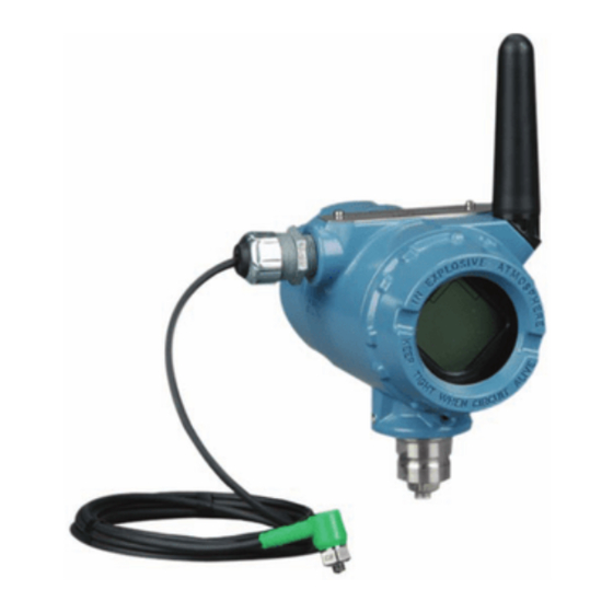
CSI 9420 Wireless Vibration
Transmitter
900 MHz
CSI 9420 Vibration Hardware Revision
®
HART
Device Revision
Field Communicator Field Device Revision
2.4 GHz
CSI 9420 Vibration Hardware Revisions
HART Device Revision
Field Communicator, Field Device Revisions
Read this manual before working with the product. For personal and system safety, and for
optimum product performance, make sure to thoroughly understand the contents before
installing, using, or maintaining this product.
The United States has two toll-free assistance numbers and one international number.
Customer Central
1-800-999-9307 (7:00 a.m. to 7:00 P.M. CST)
National Response Center
1-800-654-7768 (24 hours a day)
Equipment service needs
International
1-(952) 906-8888
The products described in this document are NOT designed for nuclear-qualified
applications.
Using non-nuclear qualified products in applications that require nuclear-qualified hardware
or products may cause inaccurate readings.
For information on Rosemount nuclear-qualified products, contact a Emerson Process
Management Sales Representative.
CSI 9420 Wireless Vibration Transmitter may be protected by one or more U.S. Patents pending.
Other foreign patents pending.
1
1
Dev v1, DD v11
2, 3
1
Dev v2, DD v1;
Dev v3, DD v6
NOTICE
CSI 9420
Advertisement
Table of Contents

Related Manuals for Emerson CSI 9420


Summary of Contents for Emerson CSI 9420
- Page 1 Using non-nuclear qualified products in applications that require nuclear-qualified hardware or products may cause inaccurate readings. For information on Rosemount nuclear-qualified products, contact a Emerson Process Management Sales Representative. CSI 9420 Wireless Vibration Transmitter may be protected by one or more U.S. Patents pending. Other foreign patents pending. www..assetweb.com/mhm...
- Page 2 NOTICE The CSI 9420 and all other wireless devices should be installed only after the 1420 Wireless Gateway has been installed and is functioning properly. Wireless devices should also be powered up in order of proximity from the 1420 Wireless Gateway, beginning with the closest.
-
Page 3: Table Of Contents
Powering the CSI 9420 ........ - Page 4 Reference Manual MHM-97408. CSI 9420 April 2010 Mounting ..........3-2 Introduction.
- Page 5 Reference Manual MHM-97408.5 CSI 9420 April 2010 APPENDIX C Overall Velocity ......... .C-1 Velocity, PeakVue®, and...
- Page 6 Reference Manual MHM-97408.5 CSI 9420 April 2010 TOC-4...
-
Page 7: Safety Messages
Reference Manual MHM-97408.5 CSI 9420 April 2010 Section 1 Overview Safety Messages ....... . . page 1-1 Overview . -
Page 8: Manual
Electrical vibration sensors such as accelerometers produce low-level signals proportional to their sensed vibration. With simple HART configuration, the CSI 9420 converts the low-level sensor signal to a wireless-enabled signal. Commissioning The transmitter can be commissioned before or after installation. It may be useful to commission it on the bench, before installation, to ensure proper operation and to become familiar with its functionality. -
Page 9: Mechanical
20 feet. External DC Terminal Block The CSI 9420 is optionally available with a terminal block, instead of a battery pack, for connecting external 10-28 VDC power (24V nominal). Sensor Make sensor connections through the cable entry in the side of the connection head. -
Page 10: Shipping Considerations For Wireless Products (Lithium Batteries):
Reference Manual MHM-97408.5 CSI 9420 April 2010 NOTE If the device has been exposed to a hazardous substance, a Material Safety Data Sheet (MSDS) must be included with the returned materials. An MSDS is required by law to be available to people exposed to specific hazardous substances. -
Page 11: Safety Messages
Reference Manual MHM-97408.5 CSI 9420 April 2010 Section 2 Configuration Safety Messages ....... . . page 2-1 Configuration Overview . -
Page 12: Configuration Overview
The device will, however, report an alert until the sensor(s) is connected, this is the expected behavior. The basic steps for configuring the CSI 9420 are as follows. The specific user interface (UI) available for performing the configuration varies depending on the host that is used. -
Page 13: Connection To The Wired Hart Interface
DCS and changes from AMS Machinery Manager are not permitted. 13. For CSI 9420 revision 3 or later, if the device is licensed for spectral data retrieval, configure storage of bulk data (spectrum and waveform) in the AMS Machinery Manager database - Data can be collected “on demand”... - Page 14 2-2 (for the battery powered version). Figure 2-2. 375 Field Communicator Connections For configuration, the CSI 9420 will receive any HART communications from a handheld Field Communicator, AMS Device Manager, or other HART-enabled host. When using a Field Communicator, any configuration changes must be sent to the transmitter by using the Send key (F2).
-
Page 15: Device Network Configuration
Key of the 1420 and other devices in the network. If the Network ID and Join Key are not identical to the settings in the 1420, the CSI 9420 will not communicate with the network. The Network ID and Join Key may be obtained from the 1420 web server on the Setup >... -
Page 16: Units
Temperature 1 Bias 1 temperature The CSI 9420 can be installed with two accelerometers, or one accelerometer with an embedded temperature sensor. Each sensor is characterized at the factory to determine the precise sensitivity. This information is included with the sensor, in the form of a certificate, and may be cross-referenced with the serial number as shown in Figure 2-3. -
Page 17: Alert Levels
Sensor Bias (Bias 1, Bias 2) Supply Voltage Alert Levels The CSI 9420 sets HART status bits to indicate when measured values exceed the configured thresholds. Each measured value has three (3) levels: Advisory, Maintenance, and Failed that may be set independently. These... -
Page 18: Burst Mode
These alerts will go away once the sensor(s) is installed correctly. Burst Mode The CSI 9420 can publish in either of two modes. Optimized Burst Mode or Generic Burst Mode. Optimized burst mode uses less power because it combines a large amount of information into a single command. -
Page 19: Optimize For Power Consumption
Power Save Publish By default, the LCD is “enabled” (even if it is not physically installed). When the LCD is enabled, the CSI 9420 displays information about its network state and its measurements. This is very helpful for configuration, installation, and commissioning. -
Page 20: Trending Parameters
WirelessHART, in fact, requires that any device on the wireless network must publish at least once per hour. For this reason, the minimum (least frequent) publish rate for which the CSI 9420 can be configured is once per hour. Publishing less frequently than this violates the network requirements. -
Page 21: Remove Power Module
Reference Manual MHM-97408.5 CSI 9420 April 2010 DeltaV versions prior to 10.3 and Ovation versions prior to 3.3, though not integrated via HART, do accept Modbus values from the wireless devices. DeltaV can also accept OPC values. Remove Power Module... -
Page 22: Configuration With 375/475 Field Communicator
MHM-97408.5 CSI 9420 April 2010 CONFIGURATION WITH The 375/475 Field Communicator configuration menu trees for the CSI 9420 are shown on the following pages. 375/475 FIELD COMMUNICATOR The menu trees for the 2.4 GHz version are shown from Figure 2-4 to Figure 2-9. - Page 23 Reference Manual MHM-97408.5 CSI 9420 April 2010 Figure 2-4. 2.4 GHz Field Communicator Menu Tree, One Accelerometer: 1 of 2 1. Overview 1. Wireless Mode 2. Overall Sensor 1 (Mapped PV) 3. PeakVue Sensor 1 (Mapped SV) 1. Configure Sensors 4.
-
Page 24: Temperature Temperature
Reference Manual MHM-97408.5 CSI 9420 April 2010 Figure 2-5. 2.4 GHz Field Communicator Menu Tree, One Accelerometer: 2 of 2 1. Lower Range Value 1. Configuration Error 2. Advise 2. Ambient Beyond 3. Maintenance 1. Lower Range Value Failure Limit 4. - Page 25 Reference Manual MHM-97408.5 CSI 9420 April 2010 Figure 2-6. 2.4 GHz Field Communicator Menu Tree, Accelerometer with embeded Temperature: 1 of 2 1. Overview 1. Wireless Mode 2. Overall Sensor 1 (Mapped PV) 3. PeakVue Sensor 1 (Mapped SV) 1. Configure Sensors 4.
- Page 26 Reference Manual MHM-97408.5 CSI 9420 April 2010 Figure 2-7. 2.4 GHz Field Communicator Menu Tree, Accelerometer with embeded Temperature: 2 of 2 1. Lower Range Value 1. Configuration Error 2. Advise 2. Ambient Beyond 3. Maintenance Failure Limit 4. Fail 3.
- Page 27 Reference Manual MHM-97408.5 CSI 9420 April 2010 Figure 2-8. 2.4 GHz Field Communicator Menu Tree, Two Accelerometers: 1 of 2 1. Overview 1. Wireless Mode 1. Overall Sensor 1 2. Overall Sensor 1 (Mapped PV) 2. PeakVue Sensor 1 3. PeakVue Sensor 1 (Mapped SV) 1.
- Page 28 Reference Manual MHM-97408.5 CSI 9420 April 2010 Figure 2-9. 2.4 GHz Field Communicator Menu Tree, Two Accelerometers: 2 of 2 1. Lower Range Value 1. Configuration Error 1. Lower Range Value 1. Configuration Error 2. Advise 2. Ambient Beyond 2. Advise 2.
- Page 29 Reference Manual MHM-97408.5 CSI 9420 April 2010 Figure 2-10. 900 MHz Field Communicator Menu Tree, 1 of 2 PV is Device 1. Tag Basic Setup Setup SV is TV is Sensor 1 is QV is 2. Variable Description Change PV…...
- Page 30 Reference Manual MHM-97408.5 CSI 9420 April 2010 Figure 2-11. 900 MHz Field Communicator Menu Tree, 2 of 2 Device Setup Process Variables Velocity Sensor 1 PeakVue Sensor 1 Supply Voltage Failed Device Maint Status Advise Status Diag/Service Measurement Failed Status...
-
Page 31: Fast Key Sequences
For the 900 MHz CSI 9420, the fast key sequences assume that Dev v1, DD v11 is being used. To use the 375/475 Field Communicator with the rev 3 CSI 9420, a rev 3 DD (Device Description file) is required. The rev 3 DD for the CSI 9420 is located on the CD that is shipped with the CSI 9420. - Page 32 Reference Manual MHM-97408.5 CSI 9420 April 2010 Table 2-10. CSI 9420 900 MHz Fast Key Sequence Function Key Sequence Menu Items Device Information 1, 1, 8 Tag, Date, Descriptor, Message, Distributor, Write Protect, Model, Dev ID, Final assbly num, Revision #’s...
-
Page 33: Configuration With Ams Device Manager
Reference Manual MHM-97408.5 CSI 9420 April 2010 CONFIGURATION WITH NOTE: The screens shown in this section are, unless otherwise indicated, for the 2.4 AMS DEVICE MANAGER GHz WirelessHART version of the device. Before performing operations in AMS Device Manager, first scan the device(s) with a wired HART modem. - Page 34 Reference Manual MHM-97408.5 CSI 9420 April 2010 To configure the wireless network settings, right click the CSI 9420 device and select Methods, then Join Network. Figure 2-14. The CSI 9420 device selected. Enter the Network ID for the wireless network. This can be obtained using the 1420 Smart Wireless Gateway Web Server, as shown below.
- Page 35 Reference Manual MHM-97408.5 CSI 9420 April 2010 Figure 2-16. Join Device to Network screen: Network ID. Figure 2-17. Join Device to Network screen: Join Key 1 Figure 2-18. Join Device to Network screen: Join Key 2. 2-25...
- Page 36 Reference Manual MHM-97408.5 CSI 9420 April 2010 Figure 2-19. Join Device to Network screen: Join Key 3. Figure 2-20. Join Device to Network screen: Join Key 4. Next, select Accept new join key. Figure 2-21. Join Device to Network screen: Accept new join key.
-
Page 37: Right Click Menu
April 2010 Right Click Menu The right click menu of the CSI 9420 device provides a quick link to the Overview, Configure, and Service Tools window. Once this window is open, you can switch between these functions by clicking the buttons on the left side of the screen. -
Page 38: Configure
Reference Manual MHM-97408.5 CSI 9420 April 2010 The Device Information shortcut button will display general information about the transmitter, including tag name. The Publish Rate shortcut button allows configuration of how often the transmitter publishes data. To configure the device, click the Guided Setup shortcut button from the Overview screen. - Page 39 You can also assign which values you want to be reported for the Primary, Secondary, Tertiary, and Quaternary variables. The “Access Control...” button is used to enable AMS Machinery Manager to make changes to the CSI 9420 configuration (e.g. alarm limits, PeakVue filter). NOTE: If the device will be commissioned in a HART DCS host (e.g.
-
Page 40: Alert Setup
Reference Manual MHM-97408.5 CSI 9420 April 2010 Alert Setup To configure alarm limits for the various measurement variables, select the “Alert Setup” branch of the Configure tree. These tabs display all the user configurable alarm parameters, based on the sensor configuration of the device. -
Page 41: Service Tools
Reference Manual MHM-97408.5 CSI 9420 April 2010 For either the 2.4 GHz device or the 900 MHz device, select the tab of the variable you wish to configure. Enter the new values for Advise, Maint, or Fail thresholds. If you want to suppress the alarm that is reported when a variable exceeds a particular limit you may un-check the associated check box. - Page 42 Reference Manual MHM-97408.5 CSI 9420 April 2010 The Variables branch of the Service Tools tree displays graphical gauges of the various measurements. The Variables tab shows the sensor values. The Device Variables tab shows the supply voltage and ambient temperature values.
- Page 43 Reference Manual MHM-97408.5 CSI 9420 April 2010 The Spectra branch of the Service Tools tree displays spectral and analysis parameter data. This branch also has tabs for configuration of spectral data acquisition settings. Spectral data can then be imported into AMS Machinery Manager for further analysis.
- Page 44 Reference Manual MHM-97408.5 CSI 9420 April 2010 The Spectra - Velocity and PeakVue Sensor tabs display spectral plots of the last acquired data. Figure 2-30. Spectra - Velocity and PeakVue Sensor tabs 2-34...
- Page 45 Reference Manual MHM-97408.5 CSI 9420 April 2010 The Spectra - Energy Bands tab displays the calculated Energy Band amplitudes. Figure 2-31. Spectra - Analysis Parameters tab 2-35...
- Page 46 Reference Manual MHM-97408.5 CSI 9420 April 2010 The Communications branch of the Service Tools tree displays network status information. Figure 2-32. Communications display The Maintenance branch of the Service Tools tree provides commands to reboot the transmitter, reload factory default configurations, enable licensed features, and temporarily enable active advertising.
-
Page 47: Ams Machinery Manager Configuration
AMS MACHINERY AMS Machinery Manager can make changes to the data acquisition settings for CSI 9420 devices that are revision 3 or later. If the device is not going to be MANAGER commissioned in a DCS host (e.g. DeltaV or Ovation), then AMS Machinery... - Page 48 Reference Manual MHM-97408.5 CSI 9420 April 2010 • Effective Fmax for the thumbnail spectrum – For the velocity thumbnail spectrum, 300 Hz is the default Fmax used by AMS Machinery Manager. This includes up to 10 orders of turning speed for an 1800 RPM machine.
-
Page 49: Waveform Or Spectrum Time
30 minutes to acquire the same waveform. The software actually imposes some gross limits on bulk data collection rates to ensure the network is not overloaded and the individual CSI 9420 devices remain responsive for non-bulk data operation, such as a change to configuration. -
Page 50: Bulk Data Trend Parameters
DC power source. Licensing the bulk data Bulk data retrieval is a licensed feature. A CSI 9420 device that is revision 3 or later is capable of having this feature enabled. Contact your Emerson retrieval feature Sales Representative or Product Support for additional details. - Page 51 Navigate to the Service Tools page, go to the Licensed Features area, and click on “Modify Licensed Features”. Select “Waveform/Spectrum” and click “Next”. Note the information displayed – it is needed by Emerson Product Support to generate the license key. Cancel out of the wizard and contact Product Support with the information provided.
- Page 52 Reference Manual MHM-97408.5 CSI 9420 April 2010 2-42...
- Page 53 Reference Manual MHM-97408.5 CSI 9420 April 2010 2-43...
- Page 54 Reference Manual MHM-97408.5 CSI 9420 April 2010 2-44...
- Page 55 Reference Manual MHM-97408.5 CSI 9420 April 2010 2-45...
- Page 56 Reference Manual MHM-97408.5 CSI 9420 April 2010 2-46...
- Page 57 Reference Manual MHM-97408.5 CSI 9420 April 2010 2-47...
- Page 58 Reference Manual MHM-97408.5 CSI 9420 April 2010 2-48...
- Page 59 Reference Manual MHM-97408.5 CSI 9420 April 2010 2-49...
- Page 60 Reference Manual MHM-97408.5 CSI 9420 April 2010 2-50...
-
Page 61: Safety Messages
Safety Messages ....... . . page 3-1 Powering the CSI 9420 ......page 3-2 General Sensor Handling Instructions . -
Page 62: Powering The Csi 9420
Pull power wires through the threaded conduit entry and attach to the bottom two screw terminals on the right (see Figure 2-1). When selecting/sizing the power supply, note that each CSI 9420 has a peak current draw of 40 mA when awake and powering sensors. -
Page 63: General Sensor Handling Instructions
Temperature 1 -40 to +125 °C The accelerometers require a DC bias. The CSI 9420 device provides the necessary bias and measures it to verify correct sensor operation. The nominal bias voltage is 2.5 volts. If the bias voltage is outside of the 2 - 3 volt range, the device generates a FAILED alert for the associated sensor. - Page 64 • Drill • Spot Face and End Mill Tool The spot face tool may be purchased form Emerson’s Machinery Health Management business. Please contact your local sales representative for assistance. MHM Part # 88101 Description: the spot face tool attaches to a standard electric drill and provides a machined surface at least 1.1 times greater than the diameter of...
-
Page 65: Preparing Sensor Mounting Locations
Reference Manual MHM-97408.5 CSI 9420 April 2010 Accelerometer Attachment Tools and Supplies 40-200 inch-lbs. Torque Wrench with 1/8" hex bit Suggested Vendor: Grainger Part # 4JW57 • Description: 3/8" drive inch-lbs. torque wrench. Any torque wrench with a range of 40 to 70 inch-lbs. and less than 5 inch-lbs. - Page 66 Reference Manual MHM-97408.5 CSI 9420 April 2010 Figure 3-2. Diagram of milling process for sensor mounting. This spot facing should result in a uniform “seat” being created. Figure 3-3. Diagram of correct (left) and incorrect (right) milling processes. Spot faced surface should be uniform on all sides.
-
Page 67: Attaching The Sensor(S)
Reference Manual MHM-97408.5 CSI 9420 April 2010 Figure 3-4. Diagram showing a tapped pilot hole. Epoxy Mount If the equipment surface has a radius of curvature less than 4", it will be necessary to grind a flat surface approximately 1/2" in diameter. If the curvature radius is greater than 4", proceed to step 2. - Page 68 Reference Manual MHM-97408.5 CSI 9420 April 2010 Figure 3-6. Accelerometer, A0322 mounting stud (included with the accelerometer), and optional A212 mounting pad (epoxy mount only). Using 1/8" allen wrench loosely screw mounting stud into mounting location. Using torque wrench with 1/8" hex bit, torque to 7-8 ft-lbs. Stud Mount...
-
Page 69: Secure Cabling
Reference Manual MHM-97408.5 CSI 9420 April 2010 Figure 3-7. Mounting illustrations for right angle Quick Connect sensors. Secure Cabling Secure the sensor cable to the machine approximately 4 to 5 inches from the mounting location using an appropriate size cable clamp. Do not curl into a bending radius of less than 2.8 inches. -
Page 70: Cabling
•6" ... 110VAC •12" ... 220VAC •2’ ... 440VAC Conduit attaches to CSI 9420 from the side of the enclosure as shown in Figure 3-9. Figure 3-9. Conduit attaches to threaded holes in the side of CSI 9420. - Page 71 Reference Manual MHM-97408.5 CSI 9420 April 2010 Sensor Leads If the sensor is installed in a high-voltage environment and a fault condition or installation error occurs, the sensor leads and transmitter terminals could carry lethal voltages. Use extreme caution when making contact with the leads and terminals.
-
Page 72: Connecting Sensors
MHM-97408.5 CSI 9420 April 2010 Connecting Sensors One or two accelerometers can be connected to the CSI 9420. Only one accelerometer plus temperature sensor can be connected to the CSI 9420. Table 3-2. Connecting One Accelerometer to the CSI 9420 Connecting One Sensor / accelerometer (Illustration below table.) - Page 73 Reference Manual MHM-97408.5 CSI 9420 April 2010 Table 3-4. Connecting One Sensor with temperature. Connecting One Sensor (accelerometer with temperature) (Illustration below table.) Connector labeled 1 Connector labeled 2 Connector labeled 3 Connector labeled 4 - Red wire - White wire...
-
Page 74: Liquid Crystal Display (Lcd)
Depending on the update rate, disabling the LCD can increase the life of the power module by as much as 40 percent. If your CSI 9420 was purchased without the optional LCD, and you wish to add this later, an upgrade kit is available, MHM part number A9400LCD. - Page 75 Reference Manual MHM-97408.5 CSI 9420 April 2010 The electronics enclosure should be grounded in accordance with local and national installation codes. This can be accomplished via the base connection, via the internal case grounding terminal, or via the external grounding terminal.
- Page 76 Reference Manual MHM-97408.5 CSI 9420 April 2010 3-16...
-
Page 77: Safety Messages
• Use extreme caution when making contact with the leads and terminals. NOTE The CSI 9420 and all other wireless devices should be installed only after the 1420 Wireless Gateway has been installed and is functioning properly. Wireless devices should also be powered up in order of proximity from the 1420 Wireless Gateway, beginning with the closest device to the 1420. -
Page 78: Verify Operation
TAG, Device ID, Network ID, Network Join Status and Device Status screens and make a measurement. NOTE: To access the DIAG button, remove the front cover of the CSI 9420. CSI 9420 2.4 GHz For information on LCD screen messages, see LCD Screen Messages, 2.4 GHz on page 5-2. - Page 79 NOTE It is normal for the CSI 9420 to have a red “X” on this screen until the sensor is installed. For more detail on a specific device, click on the tag name.
- Page 80 Reference Manual MHM-97408.5 CSI 9420 April 2010 Troubleshooting The most common cause of incorrect operation is that the Network ID or Join Key are not set correctly in the device. The Network ID and Join Key in the device must match that of the 1420 Wireless Gateway exactly. The Network ID and Join Key may be obtained from the 1420 Wireless Gateway on the Setup >...
-
Page 81: Safety Messages
Reference Manual MHM-97408.5 CSI 9420 April 2010 Section 5 Operation and Maintenance Safety Messages ....... . . page 5-1 LCD Screen Messages, 2.4 GHz . -
Page 82: Lcd Screen Messages, 2.4 Ghz
LCD SCREEN MESSAGES, 2.4 GHZ Startup Screen The following screens will display when the power module is first connected to the CSI 9420. Sequence All Segments On: used to visually determine if there are any bad segments on the LCD NIM Startup: the device is waiting for the radio to initialize. -
Page 83: Joining And Provisioning
Version Code: lists the version of the firmware in the device. Joining and Provisioning The following screens will display when the CSI 9420 is in the process of joining the network. Service Created: a request for network services has been granted to the device. Services must be obtained before the device can transfer data via the network. -
Page 84: Normal Operating Sequence Screens
Reference Manual MHM-97408.5 CSI 9420 April 2010 Set Service: a request for network services has been issued by the device. Service Rejected: a request for network services has been rejected by the network manager. Sufficent bandwidth may not be currently available. -
Page 85: Network Status Screens
Reference Manual MHM-97408.5 CSI 9420 April 2010 TV screen: Overall velocity, PeakVue, temperature, sensor bias voltage, or power supply voltage depending on how the device is configured. QV screen: Overall velocity, PeakVue, temperature, sensor bias voltage, or power supply voltage depending on how the device is configured. - Page 86 Reference Manual MHM-97408.5 CSI 9420 April 2010 Network Idle: the device is in a low power idle state. The device is not connected to the network. Network Search: the device is actively searching for a network. Network Negotiation: the device has deleted a network and is attempting to establish connection.
-
Page 87: Device Information Screens
Reference Manual MHM-97408.5 CSI 9420 April 2010 Network Disconnected: the device is disconnected from the network. Device Information The following screens will show the device diagnostics depending on the state of the device. Screens Device Information - Failure: there is a critical error which may prevent the device from operating correctly. - Page 88 Reference Manual MHM-97408.5 CSI 9420 April 2010...
-
Page 89: Lcd Screen Messages, 900 Mhz
LCD SCREEN MESSAGES, 900 MHZ Startup Screen The following screens will display when the power module is first connected to the CSI 9420. Sequence All Segments On: used to visually determine if there are any bad segments on the LCD Device Name: used to determine Device Name. -
Page 90: Normal Operating Sequence Screens
Reference Manual MHM-97408.5 CSI 9420 April 2010 Network Identification: assuming the device has the correct join key, this ID tells the user what network the device can connect with Version Code - lists the version of the firmware in the device. - Page 91 Reference Manual MHM-97408.5 CSI 9420 April 2010 SV screen - Overall velocity, PeakVue, temperature, sensor bias voltage, or power supply voltage depending on how the device is configured. TV screen - Overall velocity, PeakVue, temperature, sensor bias voltage, or power supply voltage depending on how the device is configured.
-
Page 92: Network Status Screens
Reference Manual MHM-97408.5 CSI 9420 April 2010 Network Status Screens These screeens display the network status of the device. Only one will be shown during the startup sequence or normal operating sequence. Network Status Screen 4.1: the device has yet to retrieve the information from the 1420 and is still in the process of being activated. - Page 93 Reference Manual MHM-97408.5 CSI 9420 April 2010 Network Status Screen 4.6: the device did not find the network and is in deep sleep mode to preserve battery power. Network Status Screen 4.7: the device is synchronized to a network. Network Status Screen 4.8: the device will reset.
-
Page 94: Device Information Screens
Reference Manual MHM-97408.5 CSI 9420 April 2010 Network Status Screen 4.11: the device has joined a network and has been fully configured and has multiple (2 or more) parents. Device Information The following screens will show the device diagnostics depending on the state of the device. -
Page 95: Power Module Replacement
Reference Manual MHM-97408.5 CSI 9420 April 2010 POWER MODULE Expected power module life is four (4) years at reference conditions. REPLACEMENT When power module replacement is required, remove the power module cover and remove the power module pack. Replace the pack (part number MHM-89002 or Rosemount P/N 00753-9220-XXXX) and replace the cover. - Page 96 Reference Manual MHM-97408.5 CSI 9420 April 2010 5-16...
-
Page 97: Specifications
0–100% relative humidity Transmit Rate User selectable, 60 sec. to 1 hour for the 2.4 GHz CSI 9420. User selectable, 60 sec. to about 18 hours for the 900 MHz CSI 9420. Vibration Range: RMS velocity (frequency dependent): 0.008 in/sec to >4.35 in/sec (0.20 mm/s to >110.5 mm/s) - Page 98 Reference Manual MHM-97408.5 CSI 9420 April 2010 Accuracy Parameter Typical Worst Case RMS Velocity 0.5 dB (corresponds to +/-4%) 5.0 dB PeakVue 1.0 dB (corresponds to +/-7%) 11.0 dB Temperature +/- 2.0 Measurement Precision • Vibration: 0.2 dB over 24 months •...
-
Page 99: Physical Specifications
(1) Reference conditions are 70 ° F (21 °C), two accelerometers transmit rate of once every 30 minutes, and routing data for three additional network devices, LCD disabled. (2) The housing is also available in a non-polished stainless steel. The stainless steel housing is not painted. Contact your Emerson sales representative for more information. -
Page 100: Performance Specifications
CSI 9420 with M5 LCD - 4.7 lbs (2.1 kg) Enclosure Ratings (CSI 9420) Housing option code D is NEMA 4X, and IP66. Performance EMC (ElectroMagnetic Compatibility) Specifications The 2.4 GHz CSI 9420 meets all requirements listed under IEC 61326:2006. -
Page 101: Radio Specifications
Reference Manual MHM-97408.5 CSI 9420 April 2010 Radio Specifications (2.4 GHz WirelessHART) Parameters Units Comments Operating frequency 2.4000 2.4835 Number of channels Channel separation Occupied channel At -20 dBc bandwidth Frequency Accuracy Modulation IEEE 802.15.4 DSSS Raw data rate Receiver operating... -
Page 102: Low-Power Sensor Options
Reference Manual MHM-97408.5 CSI 9420 April 2010 Low-power Sensor Options TABLE 1. CSI 9420 Sensor Options. Part number Boot Color Cable Length (ft) Cable Type Sensor Range Accelerometer A0394RI Green Polyurethane 0.02 g to 100 g from 1 kHz to 20 kHz, 0.01 in/sec to 4.35 in/sec @ 1 kHz... -
Page 103: Dimensional Drawings
Reference Manual MHM-97408.5 CSI 9420 April 2010 DIMENSIONAL DRAWINGS CSI 9420 Mount with brackets Sensor specified separately (see Low-power Sensor Options page A-6). CSI 9420 Mount without brackets 900 mHz ANTENNA Sensor specified separately (see Low-power Sensor Options page A-6). - Page 104 Reference Manual MHM-97408.5 CSI 9420 April 2010...
-
Page 105: Approved Manufacturing Locations
RF spectrum. Nearly every country Compliance requires this type of product certification. Emerson is working with governmental agencies around the world to supply fully compliant products and remove the risk of violating country directives or laws governing wireless device usage. -
Page 106: Ordinary Location Certification Csa
Reference Manual MHM-97408.5 CSI 9420 April 2010 2.4 GHz: FCC ID: LW2RM2510 IC ID: 2731A-RM2510 Ordinary Location As standard, the transmitter has been examined and tested to determine that Certification CSA the design meets basic electrical, mechanical, and fire protection... -
Page 107: Patents
At the time of this writing, FM, CSA, and ATEX approvals are pending for the external DC-power terminal block option. Diode barriers will be required if using an external power supply in a hazardous area. PATENTS The CSI 9420 uses patented Emerson technology. Among the U.S. patents issued are: • US5,943,634 •... - Page 108 Reference Manual MHM-97408.5 CSI 9420 April 2010...
-
Page 109: Overall Velocity
Velocity measurement and use it as part of their existing vibration programs. As a result, while it may not be possible to obtain a measurement result comparable to the PeakVue value reported by the CSI 9420 with a non-CSI handheld vibration analyzer, the Overall Velocity measurement is ubiquitous throughout the industry and should be easy to correlate with the results from handheld instruments. - Page 110 Overall Velocity, so it is important to ensure that the measurement conditions are similar when trying to duplicate the value reported by the CSI 9420 with that of a handheld. The CSI 9420 uses ISO 10816, which defines a measurement bandwidth of 2 Hz to 1 kHz.
- Page 111 PeakVue long before there is any significant increase in Overall Vibration. PeakVue is especially useful for monitoring rolling-element bearings. Based on years of experience with this technology, Emerson Process Management has developed alarm levels for PeakVue, which are illustrated in the graph below.
- Page 112 (for a 3600 RPM machine) are used as the default alert thresholds by the vibration transmitter. Utilizing the embedded PeakVue technology, the CSI 9420 identified developing problems at a couple of test sites during early field trials. In both cases, the problem was not visible with conventional low-frequency analysis.
- Page 113 This discussion provides some generic guidelines, given some knowledge of the variables involved, for setting the thresholds for your specific CSI 9420 installation. Keep in mind, though, that the generic methodologies described here are no substitute for first-hand knowledge of your plant.
-
Page 114: Relative" Temperature Monitoring
Reference Manual MHM-97408.5 CSI 9420 April 2010 In general, the best way to detect a developing fault related to temperature is to look for an increase in the temperature, relative to ambient, over time. This implies that, for reliable alerting, the thresholds should change as ambient temperature changes. - Page 115 Reference Manual MHM-97408.5 CSI 9420 April 2010 Use the following relationships to determine T rise • = 65 °C + serv_fact_temp; for class A insulation rise • = 85 °C + serv_fact_temp; for class B insulation rise • = 110 °C + serv_fact_temp; for class F insulation rise •...
- Page 116 Reference Manual MHM-97408.5 CSI 9420 April 2010 - 10 °C f_maintenance f_fault - 20 °C f_advisory f_fault Error Indications and Steady-state Determination Do not use any data readings collected within 30 seconds of motor start up Check for error indications •...
-
Page 117: Introduction
The input bandwidth of the measurement is approximately 20 kHz. This waveform is then digitized and analyzed within the CSI 9420 to produce the desired vibration parameters. Due to the high-frequency nature... -
Page 118: Mitigations
Reference Manual MHM-97408.5 CSI 9420 April 2010 Figure D-1. Comparison of accelerometer signal with and without interference. Refer to Figure D-1 for a comparison of the same signal measured on an accelerometer with and without interference. This is a photograph of two lab instruments. -
Page 119: Conductive Conduit
RF fields, it is strongly recommended that you consider other mitigations discussed later in this appendix. NOTE: Emerson does not recommend the use of longer cables. Conductive Conduit: Running the cable through conductive conduit provides additional shielding and increases immunity to EMI/RFI. - Page 120 Reference Manual MHM-97408.5 CSI 9420 April 2010 The upper trace (A2) is a standard (non-armor-jacketed) 3-meter cable, without conduit, with polarization matching that of the interference field, and with two ferrites installed at the accelerometer end of the cable. The resulting interference is about 10 mV peak-to-peak, which is equivalent to a perturbation of about 0.2 g's peak to the acceleration measurement.
- Page 121 Reference Manual MHM-97408.5 CSI 9420 April 2010 Figure D-4. The 3-meter / 10-ft. standard accelerometer cable with ferrites installed (as shipped from the factory).
- Page 122 Reference Manual MHM-97408.5 CSI 9420 April 2010 To meet the stated performance criteria, the armor-jacketed accelerometer cable has one (1) ferrite installed. It is Steward part number 28B0672-000, which provides 245 ohms of reactance at 100 MHz. Refer to Figure D-5 for a photograph of the armor-jacketed accelerometer with the ferrite installed as shipped from the factory.
- Page 123 CSI 9420 April 2010 All low-power sensors for use with the CSI 9420 are shipped with additional ferrites if their cable lengths exceed 3 meters. To ensure compliance with the CE directive, if the cable length exceeds 3 meters, ferrite installation at the site is required for all standard sensor configurations (1 accelerometer, 1 accelerometer with embedded temperature, or 2 accelerometers).
- Page 124 The procedure for installing the ferrites on the standard cable is as follows: After cutting the accelerometer cable to the required length, make the standard connections to the CSI 9420 terminal block and grounding screw. Snap the first of three attenuator ferrites (MHM-94985) at the location on the cable approximately 1 inch from the point where the cable enters the gland.
-
Page 125: Polarization
Reference Manual MHM-97408.5 CSI 9420 April 2010 Polarization: The maximum coupling onto the cable occurs when the polarization of the interfering signal matches the cable run. In most cases intermittent interference sources, such as hand-held walkie-talkies or tablet computers, are naturally vertically polarized because of the way a human being holds these items during normal usage. -
Page 126: Summary
CSI 9420 April 2010 Summary: To maximize immunity to EMI/RFI, consider the following when planning the installation of the CSI 9420 and its accelerometers: Minimize accelerometer cable lengths Consider running accelerometer cables in conductive conduit, grounded on both ends Use ferrites to attenuate interference that couples into the accelerometer... - Page 128 MHM-97408.5 April 2010 The Emerson lProcess Management and AMS Machinery Manager and Peakvue logos are registered trade marks of Emerson Process Management. PlantWeb is a registered trademark of one of the Emerson Process Management group of companies. HART is a registered trademark of the HART Communication Foundation.
Need help?
Do you have a question about the CSI 9420 and is the answer not in the manual?
Questions and answers