Table of Contents
Advertisement
Instruction Manual
D103292X012
Fisher
C1 Pneumatic Controllers and
™
Transmitters
Contents
. . . . . . . . . . . . . . . . . . . . . . . . . . . . . . . . .
. . . . . . . . . . . . . . . . . . . . . . . . . . . . .
. . . . . . . . . . . . . . . . . . . . . . . . . . . . . . . . .
. . . . . . . . . . . . . . . . . . . . . . . . . . . . . . .
. . . . . . . . . . . . . . . . . . . . . . . . .
. . . . . . . . . . . . . . . . . . . . . . . . . . . . . . . . . .
. . . . . . . . . . . . . . . . . . . . . . . . .
. . . . . . . . . . . . . . . . . . . . . . . . . . . . .
. . . . . . . . . . . . . . . . . . . . . . . . . . . . . .
. . . . . . . . . . . . . . . . . . . . . . . . .
. . . . . . . . . . . . . . . . . . . . . . . . . .
. . . . . . . . . . . . . . . . . . . . . . . . . .
. . . . . . . . . . . . . . . . . . . . . . . .
. . . . . . . . . . . . . . . . . . . . . . . . . . . . .
. . . . . . . . . . . . . . . . . . . . . . . . .
. . . . . . . . . . . . . . . . . . . . . . . . . . .
. . . . . . . . . . . . . . . . . . . . . . . . . . .
. . . . . . . . . . . . . . . . . . . . . . . . . . . . .
. . . . . . . . . . . . . . . . . . . . . . . . . .
. . . . . . . . . . . . . . . . . . . . . . . . . .
. . . . . . . . . . . . . . . . . . . . . . . . . . .
. . . . . . . . . . . . . . . . . . . . . . . .
. . . . . . . . . . . . . . . . . . . . . . . . . . . . . . .
www.Fisher.com
. . . . . . . . . . . . . . . . . . . . . . . .
. . . . . . . . . . . . . . . . .
. . . . . . . . . . . . . . . . .
. . . . . . . . . .
. . .
. . . . . .
. . . . . . . . . . . .
. . . . . . . . . . . . . . . . .
. . . . . . . . . .
. . . . . . . . . . . . . . . . . . . .
. . . . . . . . .
. . . . . . . . . .
. . . . . . . . . . . . . . . . . .
. . . . . . . . . . . . . . . . .
. . . . . . . . . .
. . . .
. . . . . . .
. . . . . . . . . . . . . . . . . . . . . . .
. . . . . . . . . . . . . . . . . . . . . . .
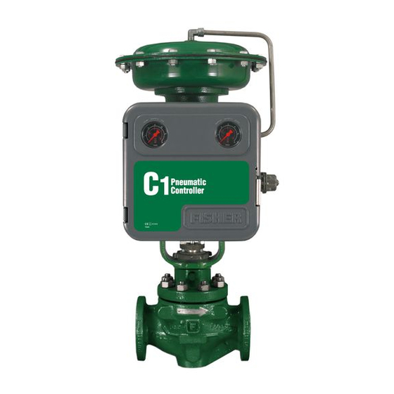
Figure 1. Fisher C1 Controller Yoke-Mounted on
Control Valve Actuator
2
2
2
2
2
6
6
7
7
7
7
9
9
10
11
11
11
11
11
W9263-1
11
12
15
15
16
16
16
16
17
17
17
19
20
20
21
21
21
21
23
23
23
23
24
C1 Controllers and Transmitters
. . . . . . . . . . . . . . . . . . . .
. . . . . . . . . . . . . . . . . . . . . . .
. . . . . . . . . . . . . . . . . . . . . . . .
. . . . . . . . . . . . . . . . .
. . . . . . . . . . . .
. . . . . . . . . . . .
. . . . . . . . . . . . . . . . . .
. . . . . . . . . . . . . . . . . . . . . . . . . . . . . . .
. . . . . . . . . . . . . . . . . . . . . . . . . . . . . . . .
. . . . . . . . . . . . . . . . . . . . . . . . . . .
. . . . . . . . . . . . . . . . . . . . .
. . . . . . . . . . . .
. . . . . . . . . . . . . . . . . . . . . . . . . . . . . .
. . . . . . . . . . . . . . . . . . . . . . . . . . . .
. . . . . . . . . . . . . . . . . . . . . . .
. . . . . . . . . . . . . . . . . .
. . . . . . . . . . . . . . . . . . . . . . . . .
. . . . . . . . . . . . . . .
. . . . . . . . . . . . . . . . . . . . . . . . . . . . . . .
March 2017
24
26
27
27
28
28
28
29
30
30
31
32
. . . . . . . . . .
33
33
33
33
34
36
37
40
Advertisement
Table of Contents

Related Manuals for Emerson Fisher C1


Summary of Contents for Emerson Fisher C1
-
Page 1: Table Of Contents
™ Transmitters Contents Figure 1. Fisher C1 Controller Yoke-Mounted on Control Valve Actuator Introduction ....... . . -
Page 2: Introduction
Introduction Scope of Manual This instruction manual provides installation, operating, maintenance, and parts information for the Fisher C1 pressure controllers and transmitters shown in figure 1. Refer to separate instruction manuals for information regarding the control valve, actuator, and accessories. - Page 3 Instruction Manual C1 Controllers and Transmitters D103292X012 March 2017 Table 1. Specifications Available Configurations Supply and Output Connections 1/4 NPT internal See table 2 Common Signal Pressure Conversions Input Signal See table 6 Type: J Gauge pressure, J vacuum, J compound pressure, or J differential pressure of a liquid or gas Proportional Band Adjustment Limits: See table 3 or 4...
- Page 4 Instruction Manual C1 Controllers and Transmitters March 2017 D103292X012 Table 1. Specifications (continued) Ambient Operating Temperature Limits temperature between -40 and 71_C (-40 and 160_F) for a transmitter set at 100% span J Standard Construction: -40 to 71_C (-40 to 160_F) J High Temperature Construction: -18 to 104_C Hazardous Area Classification (0 to 220_F)
- Page 5 3. Bourdon tube may be pressurized to limit shown without permanent zero shift. 4. With travel stop set at 110% of the range. 5. Bourdon tubes are also available in NACE compliant material. Contact your Emerson Automation Solutions sales office for additional information. Table 4. Bellows Pressure Ranges and Materials...
-
Page 6: Installation
Instruction Manual C1 Controllers and Transmitters March 2017 D103292X012 Table 6. Common Signal Pressure Conversions kg/cm 0.02 0.03 0.04 0.05 0.06 0.07 0.08 0.09 0.10 0.12 0.14 0.15 0.17 0.18 0.20 0.22 0.23 0.24 0.34 0.55 0.69 1.03 10.5 10.3 1035 1. Values as listed in ANSI/S7.4. -
Page 7: Panel Mounting
Instruction Manual C1 Controllers and Transmitters D103292X012 March 2017 Panel Mounting Refer to figure 2. Cut a hole in the panel surface according to the dimensions shown in figure 2. Remove the cap screws (key 252), brackets (key 251), and vent assembly (key 28). Slide the controller or transmitter into the cutout and reattach the brackets. - Page 8 Instruction Manual C1 Controllers and Transmitters March 2017 D103292X012 Figure 2. Panel, Wall, and Pipestand Mounting 180.8 (7.12) 63.5 63.5 (2.50) (2.50) 2 INCH (NOMINAL) PIPE 65.8 (2.59) 23.1 (0.91) VENT ASSEMBLY KNOCK-OUT KNOCK-OUT 69.1 (KEY 28) (2.72) PIPESTAND MOUNTING BACK VIEW 244.3 142.7...
-
Page 9: Pressure Connections
While use and regular maintenance of a filter that removes particles larger than 40 micrometers in diameter will suffice in most applications, check with an Emerson Automation Solutions field office and industry instrument supply medium quality standards for use with hazardous gas or if you are unsure about the proper... -
Page 10: Process Pressure
Instruction Manual C1 Controllers and Transmitters March 2017 D103292X012 Supply pressure medium must be clean, dry, and noncorrosive and meet the requirements of ISA Standard 7.0.01 or ISO 8573-1. A maximum 40 micrometer particle size in the air system is acceptable. Further filtration down to 5 micrometer particle size is recommended. -
Page 11: Vent Assembly
Instruction Manual C1 Controllers and Transmitters D103292X012 March 2017 Vent Assembly WARNING Personal injury or property damage could result from fire or explosion of accumulated gas, or from contact with hazardous gas, if a flammable or hazardous gas is used as the supply pressure medium. Because the instrument case and cover assembly do not form a gas-tight seal when the assembly is enclosed, a remote vent line, adequate ventilation, and necessary safety measures should be used to prevent the accumulation of flammable or hazardous gas. -
Page 12: Calibration: Proportional-Only Controllers
Instruction Manual C1 Controllers and Transmitters March 2017 D103292X012 Calibration: Proportional-Only Controllers Unless otherwise indicated, key number locations are shown in figure 4. Provide a process pressure source capable of simulating the process pressure range of the controller. If an output pressure gauge is not provided, install a suitable pressure gauge for calibration purposes. - Page 13 Instruction Manual C1 Controllers and Transmitters D103292X012 March 2017 For reverse-acting controllers: 4. Apply an input pressure equal to the sensing element upper range value. 5. Rotate the pressure setting knob to the maximum value. 6. Adjust the nozzle (key 54) until the controller output pressure is between 0.6 and 0.7 bar (8 and 10 psig). 7.
- Page 14 Instruction Manual C1 Controllers and Transmitters March 2017 D103292X012 For direct-acting controllers: 4. Apply an input pressure equal to the sensing element lower range value. 5. Rotate the pressure setting knob to the minimum value. 6. Adjust the nozzle (key 54) until the controller output pressure is between 0.6 and 0.7 bar (8 and 10 psig.) 7.
-
Page 15: Startup: Proportional-Only Controllers
Instruction Manual C1 Controllers and Transmitters D103292X012 March 2017 Startup: Proportional-Only Controllers (General Tuning Guidelines) Calibrate the controller prior to this procedure. 1. Be sure that the supply pressure regulator is delivering the proper supply pressure to the controller. 2. Rotate the pressure setting knob to the desired set point. 3. -
Page 16: Adjustments
Instruction Manual C1 Controllers and Transmitters March 2017 D103292X012 Figure 7. Proportional-Plus-Reset Controller Adjustment Locations RESET ADJUSTMENT KNOB PRESSURE SETTING KNOB (KEY 58) PRESSURE SETTING DIAL (KEY 6) FLAPPER (KEY 40) PROPORTIONAL BAND CALIBRATION ADJUSTER (KEY 36) NOZZLE (KEY 54) ADJUSTMENT KNOB ADJUSTER SCREWS (KEY 48) GE28281-B... -
Page 17: Adjustment: Anti-Reset Windup
Instruction Manual C1 Controllers and Transmitters D103292X012 March 2017 in effect, the time in minutes required for the controller to increase (or decrease) its output pressure by an amount equal to a proportional increase (or decrease) caused by a change in set point or process pressure. Adjustment: Anti-Reset Windup The externally mounted differential relief valve can be mounted to relieve on increasing or decreasing output pressure. - Page 18 Instruction Manual C1 Controllers and Transmitters March 2017 D103292X012 change in the opposite direction than expected. For example, while moving the calibration adjuster to increase span, the output pressure may decrease. This should be disregarded since even though the output pressure decreases, the span is increasing. Proper controller response depends on nozzle-to-flapper alignment.
-
Page 19: Calibration: Anti-Reset Windup
Instruction Manual C1 Controllers and Transmitters D103292X012 March 2017 change in the opposite direction than expected. For example, while moving the calibration adjuster to increase span, the output pressure may decrease. This should be disregarded since even though the output pressure decreases, the span is increasing. Proper controller response depends on nozzle-to-flapper alignment. -
Page 20: Startup: Proportional-Plus-Reset Controllers
Instruction Manual C1 Controllers and Transmitters March 2017 D103292X012 Startup: Proportional-Plus-Reset Controllers (General Tuning Guidelines) Calibrate the controller prior to this procedure. 1. Be sure that the supply pressure regulator is delivering the proper supply pressure to the controller. 2. Rotate the pressure setting knob to the desired set point. 3. -
Page 21: Adjustments
Instruction Manual C1 Controllers and Transmitters D103292X012 March 2017 To better understand the adjustments and overall operation of the controller, refer to the Principle of Operation section in this manual for differential gap controllers and the schematic diagram in figure 13. Adjustments Adjustment: Set Point The position of the pressure setting knob determines the location of the differential gap within the range of the... - Page 22 Instruction Manual C1 Controllers and Transmitters March 2017 D103292X012 c. Unclip the lock spring (key 72). Remove the indicator scale (key 69) and proportional band adjustment knob (key 73). d. Remove the gain adjustment bar (key 63). Flip it over so it attaches to the opposite side of the cantilever spring (key 8) as shown in figure 16 and screw it back down.
-
Page 23: Startup: Differential Gap Controllers
Instruction Manual C1 Controllers and Transmitters D103292X012 March 2017 c. With falling input pressure, the output should switch from full supply pressure back to zero when the lower switching point is reached. Reverse-acting controllers produce the opposite response. 7. Vary the process pressure and observe the switching points. Widen or narrow the differential gap by rotating the proportional band adjustment knob, then repeat the above steps. -
Page 24: Adjustment: Span
Instruction Manual C1 Controllers and Transmitters March 2017 D103292X012 Figure 11. Transmitter Adjustment Locations ZERO ADJUSTMENT KNOB (KEY 58) PRESSURE SETTING DIAL (KEY 6) FLAPPER (KEY 40) SPAN ADJUSTMENT KNOB NOZZLE (KEY 54) ADJUSTER SCREWS (KEY 48) CALIBRATION ADJUSTER (KEY 36) GE34729-B E1061 Adjustment: Span... - Page 25 Instruction Manual C1 Controllers and Transmitters D103292X012 March 2017 Provide a process pressure source capable of simulating the process pressure range of the transmitter. If an output pressure gauge is not provided, install a suitable pressure gauge for calibration purposes. Connect a pressure source to the supply pressure regulator and be sure the regulator is delivering the correct supply pressure to the transmitter.
-
Page 26: Startup: Transmitters
Instruction Manual C1 Controllers and Transmitters March 2017 D103292X012 Figure 12. Transmitter Span Adjustment IF OUTPUT IS: BELOW ABOVE 15 PSIG 15 PSIG (1.0 BAR) (1.0 BAR) MOVE ADJUSTER MOVE ADJUSTER RIGHT LEFT NOTE: 3 TO 15 PSIG (0.2 TO 1.0 BAR) OUTPUT SHOWN. FOR 6 TO 30 PSIG (0.4 TO 2.0 BAR) OUTPUT, ADJUST VALUES AS APPROPRIATE. -
Page 27: Principle Of Operation
Instruction Manual C1 Controllers and Transmitters D103292X012 March 2017 Principle of Operation The following sections describe the operation of a controller or transmitter using a Bourdon tube sensing element. The operation is the same for an instrument using a bellows sensing element (key 71, figure 25) except that movement of the beam is caused by expansion or contraction of the bellows or differential bellows. -
Page 28: Proportional-Plus-Reset Controllers
Instruction Manual C1 Controllers and Transmitters March 2017 D103292X012 This controller output pressure change feeds back to the proportional bellows, countering the pressure change in the nozzle and equalizes the relay diaphragm pressure differential. The relay valve maintains a new loading pressure according to the change in sensed pressure. -
Page 29: Transmitters
Instruction Manual C1 Controllers and Transmitters D103292X012 March 2017 The action is similar with falling output pressure. Lower feedback pressure lowers the bellows pressure, which moves the flapper away from the nozzle. This again reduces the output pressure and continues until the output pressure is zero. -
Page 30: Maintenance
Instruction Manual C1 Controllers and Transmitters March 2017 D103292X012 Maintenance If the installation includes a Fisher 67 filter regulator, periodically open the drain on the filter regulator to drain accumulated moisture. Also, push the spring-out cleaning wire on the relay orifice. Check the opening of the vent assembly (key 28, figure 2) or the opening of the remote vent pipe, if one is used. -
Page 31: Replacing Bourdon Tube
Instruction Manual C1 Controllers and Transmitters D103292X012 March 2017 Note Key 2 is used as both a supply gauge and an output gauge on units without a process pressure gauge. A quantity of 2 is required for these units. On units with a process pressure indicator gauge (key 4), key 2 is used for the output gauge. A quantity of 1 is required for these units. -
Page 32: Replacing Bellows Sensing Element
Instruction Manual C1 Controllers and Transmitters March 2017 D103292X012 Figure 15. Connecting Link BOURDON TUBE BOURDON TUBE (KEY 5) (KEY 5) LINK BEARING WASHER (KEY 31) (KEY 62) WASHER (QTY 2) LINK BEARING (KEY 62) (KEY 31) BEAM WASHER (KEY 39) (KEY 62) CONNECTING LINK (KEY 16) -
Page 33: Changing Proportional Or Reset Valve
Instruction Manual C1 Controllers and Transmitters D103292X012 March 2017 12. Check all tubing connections for leaks and the bellows yoke machine screws, tighten as necessary. Perform the appropriate calibration procedures. Changing Reset Valve 1. Disconnect the appropriate tubing and remove the reset restriction valve assembly (key 256, figure 23) by removing the screw (key 22, not shown) from the back of the case. -
Page 34: Reverse To Direct Action
Instruction Manual C1 Controllers and Transmitters March 2017 D103292X012 3. Do not invert the reversing block unless also changing the controller action from direct to reverse (or vice versa). 4. Invert the proportional band assembly (refer to figure 17): a. Turn the proportional band adjustment knob (key 73) to 10. b. - Page 35 Instruction Manual C1 Controllers and Transmitters D103292X012 March 2017 Figure 18. Reverse/Direct Acting Tubing Connections for Proportional Controllers or Transmitter PROPORTIONAL TUBING PROPORTIONAL TUBING (KEY 25) (KEY 25) RELAY TUBING RELAY TUBING (KEY 24) BELLOWS (KEY 24) (KEY 52) REVERSING BLOCK (KEY 37) NOZZLE (KEY 54) PROPORTIONAL BAND ASSY...
-
Page 36: Relay Replacement
Instruction Manual C1 Controllers and Transmitters March 2017 D103292X012 b. Unscrew the spring adjustor (key 65), removing the bias spring (key 70) and washers (key 64) with it. c. Unclip the lock spring (key 72). Remove the indicator scale (key 69) and proportional band adjustment knob (key 73). -
Page 37: Changing Output Signal Range
Instruction Manual C1 Controllers and Transmitters D103292X012 March 2017 Changing Output Signal Range Use the following information and subsequent procedures when changing the output signal range of the controller or transmitter. Use the following procedure: D For a controller or transmitter, use this procedure to change from a 0.2 to 1.0 bar (3 to 15 psig) to a 0.4 to 2.0 bar (6 to 30 psig) output signal range or vice versa (also see figure 19). - Page 38 Instruction Manual C1 Controllers and Transmitters March 2017 D103292X012 5. Unscrew the bellows screws (key 53) from each end of the mounting base (key 57). Note The bellows screws (key 53) have an O-ring (key 77, figure 20) installed beneath the bellows screw head. Remove the O-ring and obtain a replacement when re-assembling the bellows.
- Page 39 Instruction Manual C1 Controllers and Transmitters D103292X012 March 2017 13. Turn the proportional band adjustment knob to 10. If it cannot be turned to 10 loosen the spring adjustor (key 65). 14. Secure the bellows (key 52) with the bellows screws (key 53), making sure that the nozzle (key 54) is centered on the flapper (key 40).
-
Page 40: Parts Ordering
Use only genuine Fisher replacement parts. Components that are not supplied by Emerson Automation Solutions should not, under any circumstances, be used in any Fisher instrument. Use of components not supplied by Emerson Automation Solutions may void your warranty, might adversely affect the performance of the instrument, and could cause personal... -
Page 41: Parts List
0-2.0 bar, 0-0.2 MPa, and 0-30 psig 0-4.0 bar, 0-0.4 MPa, and 0-60 psig Note Contact your Emerson Automation Solutions sales office for Part Ordering information. Note Controllers with bellows sensing element use only the 2.0 bar, 0 to 0.2 MPa, and 0 to 0 to 30 psig triple scale brass and stainless steel process pressure gauges. - Page 42 Instruction Manual C1 Controllers and Transmitters D103292X012 March 2017 Figure 22. Typical Reverse Acting Fisher C1 Assembly (Refer to figure 26 for the Front View of the Case & Cover Assembly) SPRING-OUT CLEANING WIRE RELAY ASSEMBLY OPTIONAL PROCESS PRESSURE INDICATION SUBASSEMBLY (KEY NOS.
- Page 43 Instruction Manual C1 Controllers and Transmitters D103292X012 March 2017 Figure 22. Typical Reverse Acting Fisher C1 Assembly (continued) (Refer to figure 26 for the Front View of the Case & Cover Assembly) SPRING-OUT CLEANING WIRE RELAY ASSEMBLY NOTE: SUBASSEMBLY (KEY NOS.
- Page 44 Instruction Manual C1 Controllers and Transmitters March 2017 D103292X012 Figure 23. Typical Reverse Acting Fisher C1 Proportional-Plus-Reset Assembly (Refer to figure 26 for the Front View of the Case & Cover Assembly) SPRING-OUT CLEANING WIRE RELAY ASSEMBLY SUBASSEMBLY (KEY NOS.
- Page 45 Instruction Manual C1 Controllers and Transmitters D103292X012 March 2017 Figure 23. Typical Reverse Acting Fisher C1 Proportional-Plus-Reset Assembly (continued) (Refer to figure 26 for the Front View of the Case & Cover Assembly) SPRING-OUT CLEANING WIRE RELAY ASSEMBLY NOTES: ARROW DOWN—RELIEVES ON DECREASING OUTPUT (OUTPUT @ SUPPLY DURING SHUTDOWN) ARROW UP—RELIEVES ON INCREASING OUTPUT (OUTPUT @ ZERO DURING SHUTDOWN)
- Page 46 Instruction Manual C1 Controllers and Transmitters D103292X012 March 2017 Figure 24. Controller Subassembly with Bourdon Tube Sensing Element VIEW A-A GE33918-A BOURDON TUBE TRAVEL STOP SUBASSEMBLY SECTION B-B SECTION C-C SECTION A-A NOTE: KEYS 33 AND 74 ARE NOT SHOWN GE26600-C Description Description...
- Page 47 Instruction Manual C1 Controllers and Transmitters D103292X012 March 2017 Figure 25. Controller Subassembly with Either Gauge-Pressure Bellows or Differential-Pressure Bellows Sensing Element SECTION A-A SECTION B-B LINK (KEY 71M) LINK (KEY 71M) SCREW (KEY 71K) BEARING (KEY 71L) SCREW (KEY 71K) SIDE VIEW OF SUBASSEMBLY BEARING WITH GAUGE-PRESSURE...
- Page 48 Instruction Manual C1 Controllers and Transmitters D103292X012 March 2017 Description Description 98 Machine Screw, steel pl (4 req'd) Gauge and differential pressure bellow instruments 99 Washer, steel pl for Bourdon tube instruments (2 req'd) Note for bellows sensing instruments (4 req'd) Bellows Yoke, zinc A total of 5 O-rings (key 77) are used.
- Page 49 Instruction Manual C1 Controllers and Transmitters D103292X012 March 2017 Figure 26. Front View of Case and Cover Assembly COMPRESSION PLUGS CHANGE ACTION LABEL (INSIDE COVER) SECTION B-B 2X ROLL PIN ATEX MARKING COVER ASSEMBLY CASE ASSEMBLY SECTION A-A GE28278-B E1075-1...
- Page 50 Instruction Manual C1 Controllers and Transmitters March 2017 D103292X012 Mounting Parts for Panel, Wall, Description Pipestand, or Fisher Actuator Cap Screw, steel pl (not shown) (specify quantity req'd) Mounting (figures 2 and 3) 1051 and 1052 casing-mounted controller Description Mounting Plate, steel Mounting Plate, steel For yoke-mounted filter regulator For yoke mounting on...
-
Page 51: D103292X012 March
Instruction Manual C1 Controllers and Transmitters D103292X012 March 2017... - Page 52 Responsibility for proper selection, use, and maintenance of any product remains solely with the purchaser and end user. Fisher is a mark owned by one of the companies in the Emerson Automation Solutions business unit of Emerson Electric Co. Emerson Automation Solutions, Emerson, and the Emerson logo are trademarks and service marks of Emerson Electric Co.
Need help?
Do you have a question about the Fisher C1 and is the answer not in the manual?
Questions and answers