Emerson Rosemount CX1100 Reference Manual
In-situ oxygen transmitter
Hide thumbs
Also See for Rosemount CX1100:
- Reference manual (48 pages) ,
- Quick start manual (32 pages)

Related Manuals for Emerson Rosemount CX1100


Summary of Contents for Emerson Rosemount CX1100
- Page 1 Reference Manual 00809-0100-4110, Rev AB May 2023 Rosemount ™ CX1100 In-Situ Oxygen Transmitter...
- Page 2 The following instructions must be adhered to and integrated into your safety program when installing, using, and maintaining Emerson products. •...
-
Page 3: Table Of Contents
Contents Chapter 1 General information......................... 5 1.1 Overview............................5 1.2 Rosemount CX1100 Oxygen Probe and Transmitter.............. 5 1.3 Typical system package......................6 1.4 Rosemount CX1100 In-Situ Oxygen Transmitter ordering information ......7 1.5 Specifications..........................8 Chapter 2 Install............................11 2.1 Install probe..........................11 2.2 Mount remote display......................15 Chapter 3 ... - Page 4 Contents Reference Manual May 2023 00809-0100-4110 Rosemount CX1100...
-
Page 5: Chapter 1 General Information
This voltage is transmitted to the Rosemount CX1100 remote transmitter and output as an analog signal. The sensor is mounted at the end of the probe tube which extends into a flue gas duct or stack. -
Page 6: Typical System Package
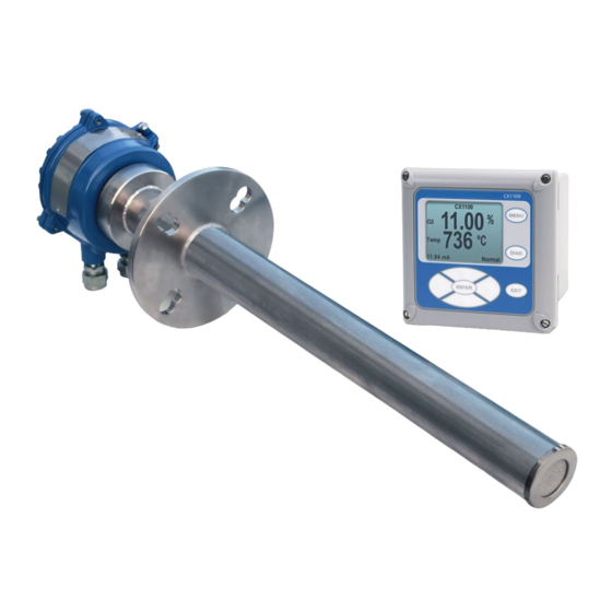
Reference Manual May 2023 00809-0100-4110 1.3 Typical system package Figure 1-1: Typical System Package A. Rosemount CX1100 Remote Transmitter B. Quick Start Guide C. Optional mounting or adapter plate D. Interconnect cable (user-supplied) E. Optional calibration gas flowmeter F. Rosemount CX1100 Probe... -
Page 7: Rosemount Cx1100 In-Situ Oxygen Transmitter Ordering Information
Reference Manual General information 00809-0100-4110 May 2023 1.4 Rosemount CX1100 In-Situ Oxygen Transmitter ordering information Model Product description CX1100 In-Situ Oxygen Transmitter Material 304L stainless steel Probe length 1.64 ft. (0.5 m) oxygen probe 3.28 ft. (1.0 m) oxygen probe 6.56 ft. (2.0 m) oxygen probe Probe mounting flange ANSI/DIN: 4.75 in. -
Page 8: Specifications
Process wetted materials are 304 stainless steel. Maximum process temperature 752 °F (400 °C) Table 1-3: Probe Terminations Specification Description Rosemount CX1100 probe ambient temperature -4 to 158 °F (-20 to 70 °C) limits Table 1-4: Remote Display Specification Description... - Page 9 TC, O , and CJC signals Heater cable 3 multi conductor 18 ga shielded cable to connect the heater control signal Rosemount CX1100 Probe Shipping weight Actual weight 19.68 in. (0.5 m) 19 lb. (8.6 kg) 13.5 lb.
- Page 10 General information Reference Manual May 2023 00809-0100-4110 Rosemount CX1100...
-
Page 11: Chapter 2 Install
Do not allow the temperature of the probe electronics to exceed 194 °F (90 °C) 2.1 Install probe Emerson can supply a weld plate for welding to the flue gas duct for new installations. Procedure 1. If using the standard square weld plate... - Page 12 E. Breather port F. Calibration gas connection Table 2-1: Removal/installation Probe length Removal envelope .5 m (19.68 in.) 750 mm (30 in.) 1 m (39.37 in.) 1250 mm (49 in.) 2 m (78.74 in.) 2250 mm (89 in.) Rosemount CX1100...
- Page 13 Reference Manual Install 00809-0100-4110 May 2023 Figure 2-2: Probe installation All dimensions are in millimeters with inches in parentheses. Square weld plate, ANSI pattern part 4512C34G01 Reference Manual...
- Page 14 145 mm (5.71 in.) Figure 2-3: Drip loop and insulation removal Note Replace insulation after installing Rosemount . B. Drip loop C. Stack duct or metal wall D. Adapter plate E. Insulation Note Probe installation may be vertical or horizontal. Rosemount CX1100...
-
Page 15: Mount Remote Display
Reference Manual Install 00809-0100-4110 May 2023 2.2 Mount remote display The remote transmitter is available in a panel mounting or wall/pipe mounting configuration. Prerequisites You need a wrench and bolts to mount the transmitter. Note Dimensions are in inches with millimeters in parentheses. Figure 2-4: Wall/Surface Mount Front View A. - Page 16 Install Reference Manual May 2023 00809-0100-4110 Figure 2-5: Wall Mount Side View Rosemount CX1100...
- Page 17 Reference Manual Install 00809-0100-4110 May 2023 Figure 2-6: Pipe Mount Bottom View A. Front panel B. Six ½-in. (12.7 mm) national pipe thread (NPT) conduit openings C. Mounting bracket D. U-bolts Reference Manual...
- Page 18 Install Reference Manual May 2023 00809-0100-4110 Figure 2-7: Pipe Mount Side View A. 2-in. (50.8 mm) pipe supplied by customer Rosemount CX1100...
- Page 19 Reference Manual Install 00809-0100-4110 May 2023 Figure 2-8: Panel Mount Front View The front panel is hinged at the bottom. The panel swings down for easy access to the wiring locations. Reference Manual...
- Page 20 Install Reference Manual May 2023 00809-0100-4110 Figure 2-9: Panel Mount Side View A. Maximum panel thickness 0.375 in. (9.52 mm) B. Panel mount gasket C. Four mounting brackets and screws provided Rosemount CX1100...
- Page 21 3. Mount at a height convenient for viewing and operating the interface. Emerson recommends approximately 5 ft. (1.5 m). 4. The keypad window on the transmitter may have an exterior protective membrane. Remove the protective membrane prior using the transmitter.
- Page 22 Install Reference Manual May 2023 00809-0100-4110 CAUTION Failure to remove the protective membrane may cause the display to appear distorted. The membrane may become difficult or impossible to remove after extended use at elevated temperatures. Rosemount CX1100...
-
Page 23: Chapter 3 Wire
Reference Manual Wire 00809-0100-4110 May 2023 3 Wire All wiring must conform to local and national codes. WARNING Failure to follow safety instructions could result in serious injury or death. Before installing the equipment, read the safety instructions at the front of this document. WARNING To maintain proper earth grounding, ensure a positive connection exists between the probe terminations housing and earth. - Page 24 2. Remove the covers from the probe and the remote transmitter (if applicable). 3. Feed all probe wiring through the conduit port of the probe. 4. Connect probe heater power leads to probe connector. Refer to Figure 3-1. Rosemount CX1100...
- Page 25 Reference Manual Wire 00809-0100-4110 May 2023 Figure 3-1: Closeup wiring diagram A. Labels B. M4 X 0.7 X 8 pan head screw machine screw (internal ground) 5. Connect O signal, thermocouple, and cold junction (CJC) wires from the probe to the transmitter 6.
- Page 26 Figure 3-2: Wiring head A. 4-20 mA out B. Heater power to probe C. Power supply D. Combustion sensor E. Shield ground F. Alternate 4-20 mA out G. Signal from probe H. Power to remote transmitter I. Alarm relay Rosemount CX1100...
- Page 27 Reference Manual Wire 00809-0100-4110 May 2023 Figure 3-3: Wiring boards A. AC power wires from power supply board to the underside of the sensor board are provided with the sensor board. B. AC input C. Heater power: terminates to underside of the sensor board. D.
- Page 28 Wire Reference Manual May 2023 00809-0100-4110 Rosemount CX1100...
-
Page 29: Chapter 4 Start Up
Reference Manual Start up 00809-0100-4110 May 2023 4 Start up Procedure 1. Apply AC line power to the remote transmitter. The probe takes approximately 45 minutes to warm up to the 1357 °F (736 °C) setpoint. The 4-20 mA signal remains at a default value of 3.5 mA, and the O reading remains at 0% through the warm-up period. - Page 30 Start up Reference Manual May 2023 00809-0100-4110 Rosemount CX1100...
-
Page 31: Calibration And Maintenance
Gas is applied to the sensor through the calibration gas fitting. New Rosemount systems are factory calibrated and are generally acceptable for initial start-up and operation. To gain high accuracy, calibrate a system during normal operating conditions. Emerson recommends calibrating on a semi-annual to annual basis for most applications; however actual calibration frequency may vary per process unit. - Page 32 Ensure that you replace the calibration cap tightly after completing calibration. Rosemount CX1100...
-
Page 33: Calibration Record
Reference Manual Calibration and maintenance 00809-0100-4110 May 2023 5.2 Calibration record Probe serial number: Probe tag number: Probe location: Date placed into service: Note Response : The time (in seconds) to observe the initial change in oxygen reading after initial closing the valve of the second calibration gas bottle. Response : The time (in seconds) in which the oxygen reading returns to process oxygen final... - Page 34 Calibration and maintenance Reference Manual May 2023 00809-0100-4110 Rosemount CX1100...
-
Page 35: Chapter 6 Rosemount ™ Cx1100 In-Situ Oxygen Transmitter Menu Trees
Reference Manual Rosemount CX1100 In-Situ Oxygen Transmitter menu trees ™ 00809-0100-4110 May 2023 6 Rosemount CX1100 In-Situ Oxygen ™ Transmitter menu trees 6.1 System menu tree Figure 6-1: System Menu Tree 1 Active Alarms 1 Diagnostics 1 Version 1 Revision 2 Status 2 Checksum 2 NV Memory Status 3 Maintenance... -
Page 36: Probe Menu Tree
1 Heater Voltage Max 2 Voltage 2 CJC Temp Max 3 Ramp Rate 3 Board Temp Max 2 Cell Voltage Max 1 Heater Ramp Rate Max 6 Heater 1 Duty Cycle Temp SP Temp 4 Heater Ramp Rate Rosemount CX1100... - Page 37 Reference Manual Rosemount CX1100 In-Situ Oxygen Transmitter menu trees ™ 00809-0100-4110 May 2023 2 Diagnostics 1 Active Alarms 1 Failed 1 Current 2 Maintenance 2 Status 3 Advisory 2 Previous 3 Acknowledge Alarms 1 Previous Alarms 1 Ack Previous Alarms 4 Maintenance 2 Ack Cal Failed 1 Version 1 Revision...
- Page 38 Rosemount CX1100 In-Situ Oxygen Transmitter menu trees Reference Manual ™ May 2023 00809-0100-4110 Rosemount CX1100...
-
Page 39: Chapter 7 Parameters
Reference Manual Parameters 00809-0100-4110 May 2023 7 Parameters 7.1 System and probe parameters Table 7-1: System Parameters Parameter label Description Active Alarms Alarms Status Alarm status bits Version Main board software version number Checksum Main board software checksum Restart Counter Main board restarted counter Offline The number of times the sensor board is disconnected from the main board since last... - Page 40 Low O Alm SP Low O alarm threshold ( 50.0% Primary variable, O %, lower range value. ( 0.0% only) Primary variable, O % upper range value ( 1.0% 50.0% AO Range Analog ouput polarity Alarm Level alarm level Rosemount CX1100...
- Page 41 Reference Manual Parameters 00809-0100-4110 May 2023 (continued) Table 7-2: Probe Parameters Parameter label Description Relay 1 Alarm Relay 1 mode Relay 2 Alarm Relay 2 mode AO Track Analog output track O sensor measurement during a calibration Cal Gas 1 Test Gas 1 value. This is the actual value of the gas being applied during the Test Gas 1 phase of a calibration.
-
Page 42: Rosemount ™ Cx1100 In-Situ Oxygen Transmitter System Alarms
Table 7-4: Probe Alarms Alarm label Help messages and recommended actions T/C Reversed The sensor heater thermocouple voltage is reading a negative voltage, indicating the thermocouple wire connections may be reversed. Check wiring. Rosemount CX1100... - Page 43 Reference Manual Parameters 00809-0100-4110 May 2023 (continued) Table 7-4: Probe Alarms Alarm label Help messages and recommended actions NV Memory Fail Checksum error was detected in the nonvolatile memory configuration data when the unit was turned on. Default values have been loaded. Check to see that your configurations have not been changed.
- Page 44 Parameters Reference Manual May 2023 00809-0100-4110 Rosemount CX1100...
-
Page 45: Appendix A Product Certifications
A.1 Directive information A copy of the Declaration of Conformity can be found at the end of the Quick Start Guide. The most recent revision of the Declaration of Conformity can be found at Emerson.com/ Rosemount. A.2 Ordinary location certification... - Page 46 Emerson Terms and Conditions of Sale are available upon request. The Emerson logo is a trademark and service mark of Emerson Electric Co. Rosemount is a mark of one of the Emerson family of companies. All other marks are the property of their respective owners.
Need help?
Do you have a question about the Rosemount CX1100 and is the answer not in the manual?
Questions and answers