Emerson CSI 9420 Reference Manual
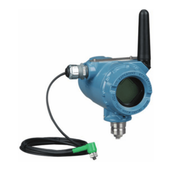
Wireless vibration transmitter
Hide thumbs
Also See for CSI 9420:
- Reference manual (128 pages) ,
- Quick installation manual (15 pages)

Related Manuals for Emerson CSI 9420


Summary of Contents for Emerson CSI 9420
- Page 1 Reference Manual MHM-97408, Rev 15 January 2015 CSI 9420 Wireless Vibration Transmitter Reference Manual...
- Page 2 The product described in this document are NOT designed for nuclear-qualified applications. Using a non-nuclear qualified product in applications that require nuclear-qualified hardware or products may cause inaccurate readings. The CSI 9420 Wireless Vibration Transmitter may be protected by one or more U.S. Patents pending. Other foreign patents pending. WARNING! Explosions could result in death or serious injury: •...
- Page 3 Machinery Health, PeakVue , and the CSI logo are the marks of one of the Emerson Process Management group of companies. The Emerson logo is a trademark and servicemark of Emerson Electric Co. All other marks are the property of their respective owners.
-
Page 5: Table Of Contents
Right-click menu ......................35 Configuration with AMS Machinery Manager ................58 2.4.1 Advanced Diagnostics application ................58 2.4.2 CSI 9420 Data Collection: Overview ................62 2.4.3 CSI 9420 publishing policy ..................63 2.4.4 Maximum network size and publishing policy settings ..........65 2.4.5... - Page 6 Contents Chapter 4 Operation and maintenance ..................87 Verify status and operation ......................87 Power module maintenance ...................... 90 Chapter 5 Velocity, PeakVue, and temperature ................91 Overall Velocity ..........................91 PeakVue ............................ 94 Temperature ..........................98 5.3.1 Relative temperature monitoring ................99 5.3.2 Absolute temperature monitoring ................
-
Page 7: Chapter 1 Introduction
High voltage that may be present on leads can cause electrical shock. This CSI 9420 device complies with Part 15 of the FCC Rules. Operation is subject to the following conditions: This device may not cause harmful interference, this device must accept any interference received, including interference that may cause undesired operation. -
Page 8: Overview
Overview The manual This Reference Manual applies to the 2.4 GHz WirelessHART version of the CSI 9420 for use with the Smart Power Module unless otherwise specified. It is optimized for use with the most recent device and software revisions (AMS Suite: Machinery Health Manager v5.61 and AMS Suite: Intelligent Device Manager v12.5). - Page 9 Introduction Device revision information Revision Current level Description Universal This is the HART version the transmitter supports. Field device This is the major revision of the transmitter and corresponds with a major interface release. When using AMS Device Manager, this revision can be found on the screen title.
- Page 10 Introduction Figure 1-2: Revision numbers in AMS Device Manager MHM-97408, Rev 15...
-
Page 11: Considerations
Make sure the instruments are installed in accordance with applicable field wiring practices. The CSI 9420 device is powered whenever the power module is installed. To avoid depleting the power module, remove it when the device is not in use. -
Page 12: Return Of Materials
Return of materials You may need to ship the CSI 9420 to an Emerson Product Service Center for return or maintenance. Before shipping, contact Emerson Product Support to obtain a Return Materials Authorization (RMA) number and receive additional instructions. -
Page 13: Chapter 2 Configuration
Configuration with AMS Machinery Manager Configuration overview You can configure the CSI 9420 either prior to installation or after the device is installed at the measurement location. You do not need to physically install or connect to the transmitter to complete the configuration. The transmitter, however, reports an alert until the sensor is connected;... - Page 14 Configuration Specify the units (English, metric, or SI) that will be used for each parameter. By default, units are set to English, unless the device is shipped to Japan. Specify which measurements (velocity, temperature, etc.) correspond to the process variables PV, SV, TV, and QV. By default, PV is the Overall Velocity on sensor 1, SV is the PeakVue measurement on sensor 1, TV is the sensor 1 bias voltage, and QV is the supply voltage.
-
Page 15: Connect To A Wired Hart Interface
2.1.1 Connect to a wired HART interface Unless the CSI 9420 is purchased pre-configured from the factory, you must connect it to a wired HART interface. This is to define device credentials that allow the device to communicate on your wireless network. You can also define other device configurations such as sensor type and alert thresholds at this time. - Page 16 Press Send to send configuration changes to the transmitter. The CSI 9420 enters “HART Listen” mode for communication on the wired interface. HART Listen is displayed on the optional LCD, if it is installed. If the device is unable to enter the HART Listen mode during its boot sequence or while performing its real-time vibration measurement, retry the initial wired HART handshaking sequence.
-
Page 17: Set The Wireless Network Configuration
Network ID and Join Key so that they match the Network ID and Join Key from the Smart Wireless Gateway. Note If the Network ID and Join Key are not identical to the gateway settings, the CSI 9420 will not communicate with the network. MHM-97408, Rev 15... -
Page 18: Configuration Options
Configuration 2.1.3 Configuration options The CSI 9420 configuration options control the following operations: • How measurement results are reported and how often are they reported • The number and type of sensors installed • How and when alerts are generated Table 2-1 shows the default device configuration. -
Page 19: Sensor Configuration
Configuration 2.1.4 Sensor configuration The CSI 9420 can be installed with two accelerometers, or with one accelerometer with an embedded temperature sensor. Table 2-2 shows the possible sensor configurations and variable mappings. Table 2-2: Possible sensor configurations and variable mappings... -
Page 20: Measurement Parameter Units
2.1.6 Alert levels The CSI 9420 sets HART status bits to indicate when measured values exceed the configured thresholds. Each measured value has three levels: Advisory, Maintenance, and Failed that can be set independently. These thresholds are pre-configured at the factory to reasonable generic values for single-stage, electric motor-driven equipment trains operating at 1200–3600 RPM. -
Page 21: Mhm-97408, Rev
Configuration Table 2-4: Default alert thresholds for vibration (continued) Advise Maintenance Failed Alert limits Report Report Report Default value Default value Default value notification notification notification Sensor 65°C 75°C 85°C temperature 149°F 167°F 185°F Bias Above: >3V – – – –... -
Page 22: Publishing Mode
2.1.7 Publishing mode The CSI 9420 can publish in either of two modes: optimized or generic (default). Optimized mode uses less power by combining a large amount of information into a single command. In this mode, only the four standard process variables (PV, SV, TV, and QV) are published at the specified update interval and cached in the Smart Wireless Gateway. -
Page 23: Minimize Power Consumption
3-12. PowerSave mode PowerSave mode is available in CSI 9420 devices that are Rev. 3 or later and it enables the device to make measurements less frequently, thereby conserving power. This is ideal when either power module life is more critical than the acquisition rate or when changes in vibration are only expected to occur over extended periods of time. -
Page 24: Trend Parameters
60 minutes (54 minutes may be optimal for older versions of the CSI 9420). When this value is set to 1X, the CSI 9420 acquires a new reading at the update rate. A PowerSave Skip Multiplier of 2X combined with a 60-minute update rate results in a new acquisition every 120 minutes (every two hours). -
Page 25: Remove The Power Module
A Rev 4 DD is recommended when using a Field Communicator to configure the CSI 9420. The DD for the CSI 9420 is located on the DVD that came with the transmitter. Refer to the Field Communicator User’s Manual for more details on DDs or go to http:// www2.emersonprocess.com/en-us/brands/Field-Communicator/Pages/SysSoftDDs.aspx... - Page 26 Configuration Figure 2-4: Field Communicator menu tree for CSI 9420, one accelerometer: 1 of 4 MHM-97408, Rev 15...
- Page 27 Configuration Figure 2-5: Field Communicator menu tree for CSI 9420, one accelerometer: 2 of 4 MHM-97408, Rev 15...
- Page 28 Configuration Figure 2-6: Field Communicator menu tree for CSI 9420, one accelerometer: 3 of 4 MHM-97408, Rev 15...
- Page 29 Configuration Figure 2-7: Field Communicator menu tree for CSI 9420, one accelerometer: 4 of 4 MHM-97408, Rev 15...
- Page 30 Configuration Figure 2-8: Field Communicator menu tree for CSI 9420, one accelerometer with temperature: 1 of 4 MHM-97408, Rev 15...
- Page 31 Configuration Figure 2-9: Field Communicator menu tree for CSI 9420, one accelerometer with temperature: 2 of 4 MHM-97408, Rev 15...
- Page 32 Configuration Figure 2-10: Field Communicator menu tree for CSI 9420, one accelerometer with temperature: 3 of 4 MHM-97408, Rev 15...
- Page 33 Configuration Figure 2-11: Field Communicator menu tree for CSI 9420, one accelerometer with temperature: 4 of 4 MHM-97408, Rev 15...
- Page 34 Configuration Figure 2-12: Field Communicator menu tree for CSI 9420, two accelerometers: 1 of 4 MHM-97408, Rev 15...
- Page 35 Configuration Figure 2-13: Field Communicator menu tree for CSI 9420, two accelerometers: 2 of 4 MHM-97408, Rev 15...
- Page 36 Configuration Figure 2-14: Field Communicator menu tree for CSI 9420, two accelerometers: 3 of 4 MHM-97408, Rev 15...
- Page 37 Configuration Figure 2-15: Field Communicator menu tree for CSI 9420, two accelerometers: 4 of 4 MHM-97408, Rev 15...
-
Page 38: Field Communicator Fast Key Sequences
2, 1 Alert Limits (Guided Setup) Sensor Power Enable Join Device to Network Configure Publishing Configure Update Rate Table 2-8: CSI 9420 common fast key sequences Function Key sequence Menu items LCD Mode Power Source Advanced Config General settings 2, 2, 3 (Manual Setup) - Page 39 Configuration Table 2-8: CSI 9420 common fast key sequences (continued) Function Key sequence Menu items Power options 2, 2, 3, 2 (Manual Setup) Power Source MHM Access Control 2, 2, 3, 6 (Manual Setup) MHM Access Control Supply power to sensor...
-
Page 40: Configuration With Ams Device Manager
2.3.1 Configure wireless network credentials in AMS Device Manager Prerequisites Before performing operations in AMS Device Manager, first scan the CSI 9420 with a wired HART modem. Right-click the HART Modem icon in Device Explorer and select Scan All Devices. -
Page 41: Right-Click Menu
2.3.2 Right-click menu The right-click menu of the CSI 9420 device in AMS Device Manager provides a quick link to the Configure, Compare, Service Tools, and Overview windows, as well as to other context menus available for the device. This document only discusses the Overview, Configure, and Service Tools windows;... - Page 42 Configuration Overview Figure 2-17: Overview window The Overview window provides a glimpse of the status of the CSI 9420, including the primary purpose variables associated with it. You can also access the following shortcuts from this page: • Device Information •...
- Page 43 Configuration Device Information From the Overview window, click Device Information to display relevant device information. Figure 2-18: Device Information window Click the Identification tab to display the device tag, long tag, device type, serial number, identifier, and description. Click the Revisions tab to display the universal, field device, software, hardware, and DD revision numbers.
- Page 44 Configuration Configure Sensors From the Overview window, click Configure Sensors to display installed sensors and current sensor configurations. Figure 2-19: Sensor Configuration window Click the Select Sensor Configuration drop-down to select a sensor configuration to apply to the installed sensors. MHM-97408, Rev 15...
- Page 45 Configuration Join Device to Network From the Overview window, click Join Device to Network to enter network identifiers and join keys that will enable the transmitter to join a wireless network. Figure 2-20: Join Device to Network window MHM-97408, Rev 15...
- Page 46 Configuration Acquire New Measurement From the Overview window, click Acquire New Measurement to display measurement statistics for Velocity, PeakVue, bias, and sensor temperature for installed sensors. This also displays supply voltage and ambient temperature information for the transmitter. Figure 2-21: Measurement Statistics window MHM-97408, Rev 15...
- Page 47 Configuration Configure Figure 2-22: Configure window The Configure window lets you configure device settings. Important To be able to edit configuration settings, select Current in the Time drop-down menu at the bottom of the screen. Guided Setup Guided Setup lets you configure device settings in a guided step-by-step process. Click Configure Sensors to display or configure installed sensors.
- Page 48 Configuration Note Sensor Power Enable is only available when the device is connected to AMS Device Manager using a USB or serial HART modem and when the device is connected to a Field Communicator. This feature is not available when the device is connected to AMS Device Manager using a WirelessHART connection.
- Page 49 Configuration Click Configure Update Rate to set how often the device acquires and reports new measurements (update rate) and to specify the number of times the transmitter skips data acquisitions between updates to the gateway (PowerSave Skip Multiplier). Click Default Burst Configuration to reset the burst configuration to default values. Click Refresh Effective Acquisition Rate to refresh the value in the Effective Acquisition Rate field.
- Page 50 Click the MHM Access Control drop-down to enable or disable Access Control for AMS Machinery Manager. Access Control allows AMS Machinery Manager to make changes to the CSI 9420 configuration. CAUTION! If the device will be commissioned in a HART DCS host (e.g., DeltaV or Ovation), do not enable AMS Machinery Manager to make changes to the configuration.
- Page 51 Configuration Click the Mapping tab to specify which measurements are reported as the Primary, Secondary, Third, and Fourth variables. Figure 2-26: Mapping tab MHM-97408, Rev 15...
- Page 52 Configuration Click the Device Information tab to display the device tag, long tag, device type, serial number, device identifier, and description, and to display the universal, field device, software, hardware, and DD revision numbers. Figure 2-27: Device Information tab MHM-97408, Rev 15...
- Page 53 Configuration Click the License tab to display installed licensable features such as the Advanced Diagnostics application. Figure 2-28: License tab Click Configure License to configure/change installed licenses. MHM-97408, Rev 15...
- Page 54 Configuration Alert Setup Alert Setup lets you configure the upper and lower range values and alarm limits for Overall Velocity, PeakVue, Bias, Sensor Temperature, Ambient Temperature, and Supply Voltage. Figure 2-29: Alert Setup Click the corresponding sensor/device variable tab and select the Report Advisory, Report Maintenance, or Report Failure check boxes to generate alarms when actual measured values exceed the thresholds specified.
-
Page 55: Service Tools
Configuration Service Tools Figure 2-30: Service Tools window The Service Tools window displays alert conditions. These include hardware and software malfunctions or parameters with values beyond specifications. Alerts Click Alerts to display active alerts for the device. MHM-97408, Rev 15... - Page 56 Configuration Variables Click Variables to display graphical gauges of sensor and device variables. Figure 2-31: Variables Click the Mapped Variables tab to display graphical gauges of variables and their mappings. Click the Sensor Variables tab to display graphical gauges of the variables for each connected sensor.
- Page 57 Configuration Trends Click Trends to display hour-long trends for each of the four measurement variables (PV, SV, TV, and QV). Figure 2-32: Trends Note The trend plots begin when Trends is selected, and continue to build as long as this remains selected. MHM-97408, Rev 15...
- Page 58 Configuration Spectra Click Spectra to display spectral and analysis parameter data and to configure spectral data acquisition settings. You can import spectral data to AMS Machinery Manager for further analysis. Note You must have the Advanced Diagnostics application license to view this feature. For more information on the Advanced Diagnostics application, see Section 2.4.1.
- Page 59 Configuration Click Velocity Spectrum x and PeakVue Spectrum x to display spectral plots of the latest acquired data for Velocity and PeakVue for connected sensors. Figure 2-34: Velocity spectrum MHM-97408, Rev 15...
- Page 60 Configuration Figure 2-35: PeakVue spectrum MHM-97408, Rev 15...
- Page 61 Configuration Click the Energy Bands tab to display calculated energy band values. Figure 2-36: Energy Bands tab MHM-97408, Rev 15...
- Page 62 Configuration Communications Click Communications to display network join status information. Figure 2-37: Communications Click the Join Mode drop-down to select when the transmitter attempts to join a network. MHM-97408, Rev 15...
- Page 63 Configuration Maintenance Click Maintenance to manage the device maintenance and log settings. Figure 2-38: Maintenance Click Routine Maintenance tab > Advertise to New Wireless Devices to enable the gateway to search for new wireless devices on the network. This helps new devices join the network faster.
-
Page 64: Configuration With Ams Machinery Manager
Modbus or OPC and not HART. CAUTION! If the CSI 9420 devices are commissioned and installed on a HART DCS or PCS that is managing and archiving device configuration information, AMS Machinery Manager should NOT be used to change the configuration. This will cause an alert in the DCS due to the mismatch. The configuration may even be overwritten by the DCS, which can cause confusion. - Page 65 Notes • It is not necessary to transmit both waveform and spectrum from the CSI 9420. The spectrum is about half as much data to transmit as a waveform. If you need the waveform, the spectrum does not have to be transmitted because the software calculates the spectrum from the stored waveform.
- Page 66 Machinery Manager Help. Enable Advanced Diagnostics application (standard) You can remotely upgrade an installed CSI 9420 that is already part of a wireless mesh network using either AMS Wireless Configurator or AMS Device Manager. There is no need to walk to the device or remove it from the field.
- Page 67 If you have an older device revision, a factory upgrade may be possible in some cases. Contact Product Support for more information. Right-click the CSI 9420 device and select Configure. From the Configure window, select Current from the Time drop-down menu.
-
Page 68: Csi 9420 Data Collection: Overview
Configuration Enable Advanced Diagnostics application (alternative) If your CSI 9420 is not installed on a wireless network, you can perform the upgrade using either a HART modem or a 375 or 475 Field Communicator. WARNING! The hazardous area rating available with the CSI 9420 does not permit either of the following operations to be performed in a hazardous area. -
Page 69: Csi 9420 Publishing Policy
Configuration To make changes to a CSI 9420, AMS Device Manager settings must allow AMS Machinery Manager to make changes. Note In some cases, if the gateway device is connected to a HART host such as DeltaV, any changes made using the AMS Machinery Manager software will be rejected. - Page 70 Waveform (time-based or alert-based) Spectrum or Waveform (on-demand) You can determine if a device has consumed all of its credits by viewing the CSI 9420 device status. In Data Import, expand the Device Hierarchy to a CSI 9420, right-click the CSI 9420, and select Get Status.
-
Page 71: Maximum Network Size And Publishing Policy Settings
Number of wireless devices Update rate (in seconds) You can have up to 100 CSI 9420 devices on a single gateway, as the HART variables (i.e. scalar values) never have an update rate faster than 60 seconds. The update rate is typically once every 60 minutes. - Page 72 Configuration Figure 2-40: CSI 9420 publishing policy menu Table 2-11: Recommended (default) publishing policy settings Interval Gateway Device Network size (D.HH:MM) credits credits Notes High-resolution data limited only to 4 devices per day with N/4 days most frequent collection interval (but never less of 2 weeks for 1-64 devices.
- Page 73 Configuration Table 2-12: Maximum network size when collecting velocity and PeakVue spectra only (no waveforms)* Interval Network size Gateway credits Device credits (D.HH:MM) 1.00:00 3.12:00 7.00:00 30.00:00 *Set-up for average velocity spectrum and PeakVue spectrum. Table 2-13: Maximum network size when collecting velocity spectrum and PeakVue waveform* Interval Network size...
-
Page 74: Waveform Or Spectrum Time
Trend values are a good way to view on-demand data from your CSI 9420 powered by a Smart Power Module because these trend values come from the Smart Wireless Gateway's cache. -
Page 75: Chapter 3 Setup
Note When selecting the power supply, note that each CSI 9420 has a peak current draw of 40 mA when awake and powering sensors. Pull the wiring through the threaded conduit entry. -
Page 76: Sensors
Temperature 1 -40°C to 125°C The accelerometers require a DC bias. The CSI 9420 provides the necessary bias and measures it to verify correct sensor operation. The nominal bias voltage is 2.5 V. If the bias voltage is outside of the 2–3 V range, the device generates a failed alert for the associated sensor. -
Page 77: Sensor Mounting/Attachment Tools And Supplies
For sensors that have been mounted before pulling the cable through the conduit or raceway to the CSI 9420, leave the cable bundled and secured to the machine. Permanent signal degradation takes place when cables are damaged. Do not step on, kink, twist, or pinch cables. - Page 78 • Plant-approved cleaner/degreaser • Plant-approved semi-permanent thread locker (e.g. Loctite) For epoxy mount, you also need the following: • 2-part epoxy (e.g. Loctite Depend [Emerson P/N A92106] or comparable) • A212 Mounting Pads Figure 3-2: A212 mounting pad • (Optional) Grinder – to create a sufficiently flat mounting surface...
-
Page 79: Prepare The Sensor Mount
Using a wire brush and plant-approved cleaner, clean and degrease the surface area. Using a 2-part epoxy (such as Emerson P/N A92106), spray the activator onto the mounting surface. Place a light coat of epoxy on the surface of the mounting pad and hold firmly against the machine spot face surface for 1 minute. -
Page 80: Attach The Sensors
Attach the sensors Figure 3-3 shows a typical accelerometer, mounting stud, and mounting pad used with the CSI 9420. The mounting pad is only necessary when doing an epoxy mount. Figure 3-3: Accelerometer, mounting stud, and optional mounting pad accelerometer... - Page 81 Setup Figure 3-4: Apply thread locker onto mounting location Using a 1/8 in. Allen key (English mounting stud) or a 4 mm Hex Allen key (metric mounting stud), loosely screw the mounting stud into the mounting location. The mounting location is the machine surface when using stud mount and the mounting pad when using epoxy mount.
- Page 82 Setup For stud mount: If the mounting stud is still not seated against the spot face after you apply the correct torque force, it indicates that the tap hole is not deep enough. Remove the mounting and tap a deeper hole. Apply a thin coat of semi-permanent thread locker to the threads on the sensor housing.
-
Page 83: Secure The Sensor Cables
Setup 3.2.6 Secure the sensor cables WARNING! All wiring should be installed by a trained and qualified electrician. Wiring must conform to all applicable local codes and regulations. Follow local codes and regulations regarding wire type, wire size, color codes, insulation voltage ratings, and any other standards. Using an appropriately sized cable clamp, secure the sensor cable to the machine approximately 4–5 in. -
Page 84: Conduit Installation Guidelines
Figure 3-10 to connect one sensor with temperature. Note You can connect one or two accelerometers to the CSI 9420. You can connect only one accelerometer with a temperature sensor. MHM-97408, Rev 15... - Page 85 Setup Figure 3-8: Connecting one sensor A. Connector 1 – red wire B. Connector 2 – white wire C. Connector 3 – blank D. Connector 4 – black wire MHM-97408, Rev 15...
- Page 86 Setup Figure 3-9: Connecting two sensors A. Connector 1 – two red wires, one from each accelerometer B. Connector 2 – white wire from one accelerometer C. Connector 3 – white wire from other accelerometer D. Connector 4 – two black wires, one from each accelerometer MHM-97408, Rev 15...
- Page 87 Setup Figure 3-10: Connecting one sensor (accelerometer with temperature) A. Connector 1 – red wire B. Connector 2 – white wire C. Connector 3 – green wire (temperature wire) D. Connector 4 – black wire Connect the power module or external DC power. Verify the connection through the status on the LCD (if available).
-
Page 88: Liquid Crystal Display (Lcd)
Setup Liquid Crystal Display (LCD) Note If you purchased the CSI 9420 without the optional LCD, and you want to add an LCD, an upgrade kit is available (P/N A9400LCDM, A9400LCD-SS, or 00753-9004-0002). Contact Product Support for more information. 3.3.1... -
Page 89: Enable The Lcd
3.3.2 Enable the LCD When you enable the LCD, the CSI 9420 displays information about its network state and its measurements. This is helpful for configuration, installation, and commissioning. The LCD provides a visual indication on the status of the device and shows its current measurements. -
Page 90: Turn On The Lcd
Off – Use this setting to disable the LCD. Note When operating the CSI 9420 with the Smart Power Module, disable the LCD in the transmitter configuration after installation to maximize power module life. While the LCD module itself consumes very little power, having it activated will alter the operating cycle of the transmitter in such a way that can impact the power module life by up to 15–20%. -
Page 91: Ground The Transmitter
Setup Use a strapping wrench to tighten the cover until it will no longer turn and the black O-ring is no longer visible. Refer to Figure 3-12 for an illustration on how to properly seal the end cap. Ground the transmitter The transmitter operates with the housing, either floating or grounded. - Page 92 Setup MHM-97408, Rev 15...
-
Page 93: Operation And Maintenance
Topics covered in this chapter: • Verify status and operation • Power module maintenance Verify status and operation Verify the status and operation of the CSI 9420 through the following: • • Field Communicator • Smart Wireless Gateway If the LCD is installed and enabled, it should display the measured values at the configured update rate during normal operation. - Page 94 Configure Update Rate Note The CSI 9420 does not publish any data to the gateway while a Field Communicator or HART modem is attached to it. After removing the leads from the Field Communicator/HART modem, the CSI 9420 senses that this connection has been removed and resumes publishing data to the gateway;...
- Page 95 A red indicator means there is a problem with either the device or its communication path. Note It is normal for the CSI 9420 to have a red “X” on the screen until the sensor is installed. Figure 4-1: Smart Wireless Gateway Click on a tag name to display more information about the device.
-
Page 96: Power Module Maintenance
Operation and maintenance Power module maintenance The Smart Power Module contains two “C” size primary lithium/thionyl chloride cells. Each cell contains approximately 2.5 grams of lithium, for a total of 5 grams in each pack. Actual power module life can vary dramatically based on operating parameters—including whether high-resolution data such as vibration waveforms and/or spectra are being retrieved from the device. -
Page 97: Velocity, Peakvue, And Temperature
The CSI 9420 uses (lower-frequency) Overall Velocity in conjunction with (higher- frequency) PeakVue to provide a holistic solution across all frequencies while optimizing the usage of the limited power and bandwidth available in a wireless device. The majority of developing fault conditions manifest in one or both of these key parameters. - Page 98 Velocity, PeakVue, and temperature Figure 5-1: Velocity waveform Figure 5-2: PeakVue waveform MHM-97408, Rev 15...
- Page 99 Velocity, so ensure that the measurement conditions are similar when trying to duplicate the value reported by the CSI 9420 with a handheld. The CSI 9420 uses ISO 10816, which defines a measurement bandwidth of 2 Hz to 1 kHz. The ISO 10816 general fault levels at...
-
Page 100: Peakvue
1.0 in/s PeakVue ™ PeakVue is a patented Emerson technology that is very useful for isolating high- frequency phenomena associated with developing faults, especially in rolling-element bearings. The premise for PeakVue is that the high-frequency components are not readily detected with more conventional measurements such as Overall Velocity, low-frequency energy (LFE), or digital overall. - Page 101 For frequent automated monitoring, such as that offered by the CSI 9420, the levels can be increased for most balance of plant equipment running between 900 and 4000 RPM. You can use the "rule of tens" as a simple but effective approach to monitoring PeakVue on most rolling element bearing machines.
- Page 102 The appropriate alerts for a given machine will be a function of its design, service, and turning speed. Utilizing the embedded PeakVue technology, the CSI 9420 identified developing problems at a couple of test sites during early field trials. In both cases, the problem was not visible with conventional low-frequency analysis.
- Page 103 Velocity, PeakVue, and temperature The defective bearing was removed and Figure 5-7 shows the developing problem that was the source of the impacting. After replacing the bearing, the PeakVue vibration is significantly reduced, as shown in Figure 5-8, indicating that the problem has been resolved.
-
Page 104: Temperature
This section provides some generic guidelines, given some knowledge of the variables involved, for setting the thresholds for your specific CSI 9420 installation. However, the generic methodologies described here are no substitute for first-hand knowledge of your plant. -
Page 105: Relative Temperature Monitoring
Velocity, PeakVue, and temperature 5.3.1 Relative temperature monitoring The recommended generic guidelines for setting the thresholds based on the relative change are: = 10°C increase Advise = 15°C increase Maintenance = 20°C increase Failed Assuming that the ambient temperature is 25°C, when operating at steady-state, you have determined that the normal temperature at this point on your equipment is 55°C. - Page 106 Velocity, PeakVue, and temperature where serv_fact_temp = • 5 for service factor of 1.15 or greater • -5 for either open or totally enclosed fan cooled (TEFC) motors, and service factor of • 0 for either totally enclosed non-ventilated (TENV) motors or motors with encapsulated windings, and service factor of 1.0 If elevation >...
-
Page 107: Accelerometer Emi And Rfi Considerations
The input bandwidth of the measurement is approximately 20 kHz. This waveform is then digitized and analyzed within the CSI 9420 to produce the desired vibration parameters. Due to the high-frequency nature of the measurement, it is inherently susceptible to electromagnetic interference (EMI) and radio frequency interference (RFI), which can cause distortions in the measurement. - Page 108 Accelerometer EMI and RFI considerations Figure 6-1: Accelerometer signal with and without interference Signal measured with no RFI effect. Signal in the presence of interference on a completely unmitigated accelerometer. Frequency spectrum representation of the signal with interference. MHM-97408, Rev 15...
-
Page 109: Mitigate Interference
Accelerometer EMI and RFI considerations Mitigate interference The following are four basic things you can do to reduce EMI and RFI on measurements: • Use a shorter cable, if possible. For more details, see Section 6.1.1. Note The leads on the sensor cables, as delivered, are specially prepared for ease of installation. Before attempting to cut the cables, be aware that cutting cables is associated with significant additional rework to correctly prepare the sensor for installation. - Page 110 Accelerometer EMI and RFI considerations Figure 6-2 shows how to run the accelerometer through a conduit that is grounded on both ends. As a general rule, the transmitter housing itself is grounded through the base where it is mounted. Since the conduit is electrically connected to the transmitter housing, this effectively grounds the conduit at the transmitter end.
-
Page 111: Install Ferrites
Accelerometer EMI and RFI considerations 6.1.3 Install ferrites Note The accelerometers are shipped with ferrites installed at the accelerometer end. To maintain the optimum performance of the accelerometer, do not remove the ferrites. To meet the stated performance criteria, the standard accelerometer cable has two (2) ferrites installed. - Page 112 The performance of the accelerometer is not maintained beyond a 3-m (10-ft) cable-length unless you install additional ferrites. All low-power sensors for use with the CSI 9420 are shipped with additional ferrites if their cable lengths exceed 3 meters. To ensure compliance with the CE directive, if the cable...
- Page 113 Accelerometer EMI and RFI considerations From a compliance perspective, you do not need to install the ferrites if the cable is in a ferromagnetic conduit (such as galvanized steel) because this type of conduit provides additional shielding. Note that the conduit entry of the device is ½ inch NPT. If you install ferrites with a conduit, you will need a wider conduit ( ¾...
- Page 114 Armor-jacketed cable and ferrites (pre-installation) Install ferrites on a standard cable Make standard connections to the CSI 9420 terminal block and grounding screw. Snap the first of three attenuator ferrites (MHM-94985) at the location on the cable approximately 1 in. from the point where the cable enters the gland.
- Page 115 Ferrites installed on a standard cable Install ferrites on an armor-jacketed cable Make standard connections to the CSI 9420 terminal block and grounding screw. Slide the first of the three ferrites at the location on the cable approximately 1 in.
- Page 116 Accelerometer EMI and RFI considerations Figure 6-8: Ferrites installed on an armor-jacketed cable You need an additional ferrite for devices that use external DC supply. This ferrite is included with the transmitter if you order the external power option. Figure 6-9: Transmitter using an external power option with ferrites installed This is a snap-on ferrite.
- Page 117 Accelerometer EMI and RFI considerations The ferrite in this example is Fair-Rite P/N 0431164281, which has a reactance that ranges from 28 Ω at 1 MHz to 310 Ω at 100 MHz and 240 Ω at 250 MHz. It supports a maximum cable diameter of 0.260 inch (6.6 mm).
-
Page 118: Reduce Polarized Interference
Accelerometer EMI and RFI considerations Figure 6-10 also shows that ferrites provide a huge amount of RFI suppression and are needed to maintain measurement integrity in the presence of strong electromagnetic interference. Do not remove the ferrites installed on the accelerometer cables that are shipped from the factory, even if you mitigate interference using other methods. - Page 119 Accelerometer EMI and RFI considerations Figure 6-12: RFI source polarization coincident with long cable run (maximum interference) MHM-97408, Rev 15...
-
Page 120: Summary
Accelerometer EMI and RFI considerations 6.1.5 Summary To maximize immunity to EMI/RFI, consider the following when planning the installation of the CSI 9420 and its accelerometers: Required • Use ferrites to attenuate interference that couples into the accelerometer cable. •... -
Page 121: Appendix A Specifications And Reference Data
°F, and °C. It can also display updates at a transmit rate of up to once per minute. Humidity limits 0–95% relative humidity Transmit rate User-selectable, 60 seconds to 1 hour for the 2.4 GHz CSI 9420. MHM-97408, Rev 15... - Page 122 Specifications and reference data Measurement Range RMS velocity (frequency dependent): 0.008 in/s to >4.35 in/s (0.20 mm/s to >110.5 mm/s) PeakVue: 0.02 g to 80 g (0.2 m/s to 785 m/s PeakVue details: 51.2 kHz sampling rate, 4096 samples/block, 1000 Hz high pass filter Accuracy For vibration over stated frequency response (at room temperature)
-
Page 123: Physical Specifications
(1) Reference conditions are 70 °F (21 °C), two accelerometers with a transmit rate of once every 60 minutes, and routing data for three additional network devices, LCD disabled, no time-based collection of energy band. (2) The housing is also available in non-polished stainless steel. Contact an Emerson sales representative for more information. MHM-97408, Rev 15... -
Page 124: Performance Specifications
–40°C to 85°C –40°F to 185°F –40°F to 185°F Without LCD display –40°C to 85°C –40°C to 85°C Electromagnetic compatibility (EMC) The 2.4 GHz CSI 9420 meets all requirements listed under IEC 61326:2006. Radio specifications Parameter Typical Units Comments Operating frequency 2.4000... -
Page 125: Low-Power Sensors (Special Order And Standard)
Specifications and reference data Low-power sensors (special order and standard) Table A-2: Special order models Color Cable Part number code length (ft) Cable type Sensor range Accelerometer A0394RI A0394RI-2 Polyurethane A0394RI-3 A0394RA A0394RA-2 Armor 0.02 g to 80 g from 1 kHz to 20 kHz A0394RA-3 Green 0.01 in/s to 4.35 in/s at 1 kHz... - Page 126 Specifications and reference data Table A-3: Standard order models Color Cable Part number code length (ft) Cable type Sensor range Accelerometer A0394RI-1 Polyurethane A0394RI-4 0.02 g to 80 g from 1 kHz to 20 kHz Green 0.01 in/s to 4.35 in/s at 1 kHz A0394RA-1 Armor A0394RA-4...
-
Page 127: Dimensional Drawings
Specifications and reference data Dimensional drawings Sensors are specified separately. Dimensions are in inches (millimeters). Figure A-1: CSI 9420 with sensor and mounting brackets Figure A-2: CSI 9420 with long-range and extended antennas MHM-97408, Rev 15... -
Page 128: Sensor Mounting Diagrams
Specifications and reference data Sensor mounting diagrams Figure A-3: Milling process This spot facing should create a uniform seat. MHM-97408, Rev 15... - Page 129 Specifications and reference data Figure A-3 shows specifications for drilling and spot face grinding when mounting accelerometers using the stud mount method, and Figure A-4 shows the correct and incorrect milling process. Figure A-4: Correct and incorrect milling Note Properly align the drill so that the tapped hole is perpendicular to the mounting surface. MHM-97408, Rev 15...
- Page 130 Specifications and reference data Figure A-5 shows the specifications for drilling, tapping a pilot hole, and torqueing the mounting stud when mounting the sensor. Figure A-5: Accelerometer mounting MHM-97408, Rev 15...
-
Page 131: Appendix B Product Certifications
RF spectrum. Nearly every country requires this type of product certification. Emerson works with governmental agencies around the world to supply fully compliant products and remove the risk of violating country directives or laws governing wireless device usage. - Page 132 Product certifications FCC ID: LW2RM2510 IC ID: 2731A-RM2510 Ordinary location certification (CSA) As standard, the transmitter has been examined and tested to determine that the design meets basic electrical, mechanical, and fire protection requirements by CSA, a nationally recognized testing laboratory (NRTL) as accredited by the Federal Occupational Safety and Health Administration (OSHA).
-
Page 133: Hazardous Locations Certificates
Product certifications Hazardous locations certificates The CSI 9420 carries multiple certificates for operation in hazardous locations. For a complete listing of specific approvals, please reference our website. Note The markings that appear on the transmitter housing determine whether a device is suitable for operation in a specific hazardous location. - Page 134 Product certifications MHM-97408, Rev 15...
-
Page 135: Appendix Clcd Screen Messages
LCD screen messages Appendix C LCD screen messages Startup screen sequence These are the screens when the power module is first connected to the CSI 9420. LCD screen Meaning Description Used to visually determine if there are any All Segments On bad segments on the LCD. - Page 136 LCD screen messages LCD screen Meaning Description Acquire The device powers up the DSP and prepares Preparation for data acquisition. Acquire Data The device is acquiring and processing data. Device 8-character user entered tag. Information Tag Device identifier that makes up the HART long address.
- Page 137 Join Key. Version Code Displays the firmware version of the device. Joining and provisioning These are the screens when the CSI 9420 is in the process of joining the network. LCD screen Meaning Description The request for network services has been granted to the device.
- Page 138 LCD screen messages LCD screen Meaning Description The request for network services has been Set Service issued to the device. The request for network services has been rejected by the network manager. Service Rejected Sufficient bandwidth may not currently be available.
- Page 139 LCD screen messages LCD screen Meaning Description Acquire Data The device is acquiring and processing data. Displays the overall velocity, PeakVue, temperature, sensor bias voltage, or power PV screen supply voltage depending on how the device is configured. Displays the overall velocity, PeakVue, temperature, sensor bias voltage, or power SV screen supply voltage depending on how the device...
- Page 140 Shows how long the device sleeps between Sleep times it wakes up and collects/publishes data. Network status screens These screens display the network status of the CSI 9420. LCD screen Meaning Description The device has yet to retrieve information...
- Page 141 LCD screen messages LCD screen Meaning Description Network Search The device is searching for a network. Network The device has detected a network and is Negotiation attempting to establish connection. The device has joined the network and has Network established connection with the network Connected manager.
- Page 142 Meaning Description Network The device is disconnected from the network. Disconnected Device diagnostic screens These screens show the state of the CSI 9420. LCD screen Meaning Description There is critical error which may prevent the Device Failure device from operating correctly.
- Page 143 LCD screen messages LCD screen Meaning Description The terminal voltage has reached a critical level. If the device is power module operated, the Supply Failure power module should be replaced. If the device is line-powered, the supply voltage should be increased. More Status At least one device parameter is on alert.
- Page 144 LCD screen messages MHM-97408, Rev 15...
-
Page 145: Index
41, 42, 48 data collection configure publishing 41, 42, 48 AMS Machinery Manager 62, 63 configure sensors 36–40 CSI 9420 62–65 configure units 41, 42, 48 Smart Wireless Gateway 62–65 Configure window 41, 42, 48 Data Import... - Page 146 5, 6 62–65 installing ferrites power wiring 105, 108, 109, 111 installing LCD powering the CSI 9420 interference, mitigating PowerSave mode PowerSave Skip Multiplier prepare sensor mount preparing the sensor mount epoxy mount enabling 83, 84...
- Page 147 Index sensor sensitivity temperature limits 5, 6 sensors trending Energy Band parameters attaching trending of parameters cable length trends 49–52, 56, 57 connecting turning on the LCD mounting tools 71, 72 operating limit special order units standard update rate Smart Power Module removing spectral data 49–52, 56, 57...
- Page 148 All rights reserved. The Emerson logo is a trademark and service mark of Emerson Electric Co. All other marks are property of their respective owners.
Need help?
Do you have a question about the CSI 9420 and is the answer not in the manual?
Questions and answers