Emerson Rosemount 8732EM Reference Manual
Transmitter with hart protocol
Hide thumbs
Also See for Rosemount 8732EM:
- Quick start manual (32 pages) ,
- Quick start manual (33 pages) ,
- Quick start manual (32 pages)

Related Manuals for Emerson Rosemount 8732EM


Summary of Contents for Emerson Rosemount 8732EM
- Page 1 Reference manual 00809-0100-4444, Rev AF December 2017 ® Rosemount 8732EM Transmitter with HART Protocol Reference Manual...
-
Page 3: Table Of Contents
Contents Contents Chapter 1 Safety messages ......................1 Chapter 2 Introduction ........................5 System description ........................5 Product recycling/disposal ......................7 Chapter 3 Sensor Installation ......................9 Handling and Lifting Safety ......................9 Location and Position ........................ 10 Sensor Installation ........................12 Process reference connection ....................20 Chapter 4 Remote Transmitter Installation .................. - Page 4 Contents 4-20 mA loop verification ......................119 ™ SMART Meter Verification ......................120 9.10 Run manual SMART Meter Verification ..................123 9.11 Continuous SMART Meter Verification ..................124 9.12 SMART Meter Verification test results ..................125 9.13 SMART Meter Verification measurements ................127 9.14 Optimizing the SMART Meter Verification ................
- Page 5 Contents Safety messages ........................217 Universal capability ........................218 Three step process ........................218 Wiring the universal transmitter ....................219 Rosemount sensors ......................... 219 Brooks sensors .........................223 Endress and Hauser sensors .....................225 Fischer and Porter sensors ....................... 226 Foxboro sensors ........................233 D.10 Kent Veriflux VTC sensor ......................237 D.11...
- Page 6 Contents ® Rosemount 8732EM Transmitter with HART Protocol Reference Manual...
-
Page 7: Chapter 1 Safety Messages
The products described in this document are NOT designed for nuclear-qualified applications. Using non-nuclear qualified products in applications that require nuclear- qualified hardware or products may cause inaccurate readings. For information on Rosemount nuclear-qualified products, contact your local Emerson Process Management Sales Representative. Reference manual... - Page 8 Safety messages WARNING! Explosion hazards. Failure to follow these instructions could cause an explosion, resulting in death or serious injury. • If installed in explosive atmospheres [hazardous areas, classified areas, or an “Ex” environment], it must be assured that the device certification and installation techniques are suitable for that particular environment.
- Page 9 Safety messages NOTICE Damage hazards. Failure to follow these instructions could resulting damage or destruction of equipment. • The sensor liner is vulnerable to handling damage. Never place anything through the sensor for the purpose of lifting or gaining leverage. Liner damage may render the sensor inoperable.
- Page 10 Safety messages ® Rosemount 8732EM Transmitter with HART Protocol Reference Manual...
-
Page 11: Chapter 2 Introduction
Introduction Introduction Topics covered in this chapter: • System description • Product recycling/disposal System description The 8700M Magnetic Flowmeter Platform consists of a sensor and a transmitter. The sensor is installed in-line with the process piping; the transmitter can be integrally mounted or remotely mounted to the sensor. - Page 12 Introduction Figure 2-3: 8705 flanged sensor Figure 2-4: 8711 wafer sensor Figure 2-5: 8721 hygienic sensor The flow sensor contains two magnetic coils located on opposite sides of the sensor. Two electrodes, located perpendicular to the coils and opposite each other, make contact with the liquid.
-
Page 13: Product Recycling/Disposal
Introduction Figure 2-6: 8705 Cross Section Product recycling/disposal Recycling of equipment and packaging should be taken into consideration and disposed of in accordance with local and national legislation/regulations. Reference manual... - Page 14 Introduction ® Rosemount 8732EM Transmitter with HART Protocol Reference Manual...
-
Page 15: Chapter 3 Sensor Installation
Sensor Installation Sensor Installation Topics covered in this chapter: • Handling and Lifting Safety • Location and Position • Sensor Installation • Process reference connection This chapter provides instructions for handling and installing the flow sensor with or without an integrally mounted transmitter. Related information Remote Transmitter Installation Handling and Lifting Safety... -
Page 16: Location And Position
Sensor Installation Location and Position 3.2.1 Environmental considerations To ensure maximum transmitter life, avoid extreme temperatures and excessive vibration. Typical problem areas include the following: • High-vibration lines with integrally mounted transmitters • Tropical/desert installations in direct sunlight • Outdoor installations in arctic climates Remote mounted transmitters may be installed in the control room to protect the electronics from the harsh environment and to provide easy access for configuration or service. - Page 17 Sensor Installation Figure 3-2: Flow direction arrow 3.2.4 Sensor piping location and orientation The sensor should be installed in a location that ensures it remains full during operation. Depending on where it is installed, orientation must also be considered. • Vertical installation with upward process fluid flow keeps the cross-sectional area full, regardless of flow rate.
-
Page 18: Sensor Installation
Sensor Installation 3.2.5 Electrode orientation The electrodes in the sensor are properly oriented when the two measurement electrodes are in the 3 and 9 o’clock positions or within 45 degrees from the horizontal, as shown on the left side of Figure 3-4. - Page 19 Sensor Installation Note Metallic or spiral-wound gaskets should not be used as they will damage the liner face of the sensor. If spiral wound or metallic gaskets are required for the application, lining protectors must be used. Figure 3-5: Gasket placement for flanged sensors Grounding ring and gasket (optional) Customer-supplied gasket Bolts...
- Page 20 Sensor Installation If leakage occurs at the suggested torque values, the bolts can be tightened in additional 10% increments until the joint stops leaking, or until the measured torque value reaches the maximum torque value of the bolts. Practical consideration for the integrity of the liner often leads to distinct torque values to stop leakage due to the unique combinations of flanges, bolts, gaskets, and sensor liner material.
- Page 21 Sensor Installation Table 3-2: Suggested flange bolt torque values for Rosemount 8705 (ASME) (continued) Fluoropolymer liners Other liners Size Class 150 Class 300 Class 150 Class 300 Code Line Size (pound-feet) (pound-feet) (pound-feet) (pound feet) 2.5-in. (65 mm) 3-in. (80 mm) 4-in.
- Page 22 Sensor Installation Table 3-3: Suggested flange bolt torque values for Rosemount 8705 sensors with fluoropolymer liners (EN 1092-1) (continued) Fluoropolymer liners (in Newton-meters) Size code Line size PN 10 PN 16 PN 25 PN 40 14-in. (350 mm) 16-in. (400 mm) 18-in.
- Page 23 Sensor Installation Figure 3-7: Wafer sensors installation components and assembly requirements Ground ring (optional) Customer supplied gaskets Spacer installation (horizontal meters) Spacer installation (vertical meters) O-ring Installation studs, nuts, and washers (optional) Wafer alignment spacer Flow Gaskets The sensor requires a gasket at each process connection. The gasket material selected must be compatible with the process fluid and operating conditions.
- Page 24 Sensor Installation Table 3-5: Rosemount alignment spacers (continued) Line size Dash-no. (-xxxx) (in) (mm) Flange rating 0B15 JIS 40K AA15 ASME- 150# AA20 ASME - 150# AA30 ASME - 150# AA40 ASME - 150# AA60 ASME - 150# AA80 ASME - 150# AB15 ASME - 300# AB20...
- Page 25 Sensor Installation Table 3-6: Stud specifications Nominal sensor size Stud specifications 0.15–1-in. (4–25 mm) 316 SST ASTM A193, Grade B8M, Class 1 threa- ded mounted studs 1½–8-in. (40–200 mm) CS, ASTM A193, Grade B7, threaded mounting studs Figure 3-8: Flange bolt torquing sequence Installation Insert studs for the the bottom side of the sensor between the pipe flanges and center the alignment spacer in the middle of the stud.
-
Page 26: Process Reference Connection
Sensor Installation Table 3-7: Rosemount 8711 torque specifications (continued) Size code Line size Pound-feet Newton-meter 8-in. (200 mm) 3.3.3 Sanitary senors Gaskets The sensor requires a gasket at each of its connections to adjacent devices or piping. The gasket material selected must be compatible with the process fluid and operating conditions. - Page 27 Sensor Installation Use the Process reference options table to determine which process reference option to follow for proper installation. Table 3-8: Process reference options Grounding Reference elec- Lining protec- Type of pipe straps Grounding rings trode tors Conductive un- Figure 3-10 Figure 3-11 Figure 3-13 Figure 3-11...
- Page 28 Sensor Installation Figure 3-11: Grounding with grounding rings or lining protectors in conductive pipe Grounding rings or lining protectors Figure 3-12: Grounding with grounding rings or lining protectors in non-conductive pipe Grounding rings or lining protectors ® Rosemount 8732EM Transmitter with HART Protocol Reference Manual...
- Page 29 Sensor Installation Figure 3-13: Grounding with reference electrode in conductive unlined pipe Figure 3-14: Grounding for line sizes 10-in. and larger Reference manual...
- Page 30 Sensor Installation ® Rosemount 8732EM Transmitter with HART Protocol Reference Manual...
-
Page 31: Remote Transmitter Installation
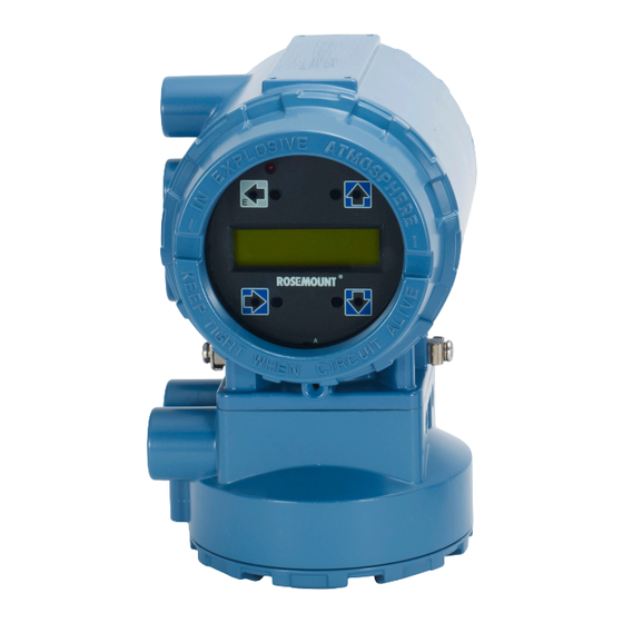
Remote Transmitter Installation Remote Transmitter Installation Topics covered in this chapter: • Pre-installation • Transmitter symbols • Mounting • Wiring This chapter provides instructions for installing and wiring a remotely mounted transmitter. Related information Sensor Installation Pre-installation Before installing the transmitter, there are several pre-installation steps that should be completed to make the installation process easier: •... - Page 32 Remote Transmitter Installation Table 4-1: Hardware switch default settings Setting Factory configuration Alarm mode High Internal/external analog power Internal Internal/external pulse power External Transmitter security The analog power switch and pulse power switches are not available when ordered with intrinsically safe output, ordering code B. In most cases, it is not necessary to change the setting of the hardware switches.
- Page 33 Remote Transmitter Installation Figure 4-1: Rosemount 8732EM Dimensional Drawing 7.49 [190,0] 6.48 1.94 [164,6] [49,0] 3.00 [128] [76,2] 8.81 [224,0] 10.5 [130] 3.07 [78,0] 2.71 [128] [76,2] 11.02 [280.0] 6.48 [164,6] 5.82 [148,0] 2.71 1.97 [68,8] [50,0] Conduit entry ½–14 NPT or M20...
-
Page 34: Transmitter Symbols
Remote Transmitter Installation Table 4-2: Electrical Data (continued) Rosemount 8732EM Flow Transmitter Pulsed circuit Internally powered (Active): Outputs up to 12VDC, 12.1mA, 73mW Externally powered (Passive): Input up to 28VDC, 100mA, 1W 4-20mA output circuit Internally Powered (Active): Outputs up to 25mA, 24VDC,... -
Page 35: Wiring
Remote Transmitter Installation Attach the mounting bracket to the instrument pole and securely tighten the fasteners. Figure 4-2: Mounting bracket A. U-bolt B. Mounting bracket C. Transmitter D. Fasteners (example configuration) To enable correct orientation, the LOI can be rotated in 90 degree increments up to 180 degrees. - Page 36 Remote Transmitter Installation • For installations with non-intrinsically safe electrode circuit, or when using the combination cable, a single dedicated conduit run for the coil drive and electrode cable between the sensor and the remote transmitter may be acceptable. Removal of the barriers for intrinsic safety isolation is permitted for non-intrinsically safe electrode installations.
- Page 37 Remote Transmitter Installation 4.4.3 Sensor to transmitter wiring Integral mount transmitters Integral mount transmitters ordered with a sensor will be shipped assembled and wired at the factory using an interconnecting cable. Use only the factory supplied cable provided with the instrument. For replacement transmitters use the existing interconnecting cable from the original assembly.
- Page 38 Remote Transmitter Installation Table 4-3: Component cable kits - standard temperature (-20°C to 75°C) (continued) Cable kit # Description Individual cable Alpha p/n 08732-0065-0004 Kit, component cables, Coil 2442C (meters) Std temp (includes Coil Instrinsically Safe Blue Not available and I.S. Electrode) Electrode Table 4-4: Component cable kits - extended temperature (-50°C to 125°C)
- Page 39 Remote Transmitter Installation Figure 4-5: Individual component cables 17 18 19 Coil drive Electrode Twisted, stranded, insulated 14 AWG conductors Drain Overlapping foil shield Outer jacket Twisted, stranded, insulated 20 AWG conductors • 1 = Red • 2 = Blue •...
- Page 40 Remote Transmitter Installation Figure 4-6: Combination coil and electrode cable Electrode shield drain Overlapping foil shield Outer jacket • 1 = Red • 2 = Blue • 3 = Drain • 17 = Reference • 18 = Yellow • 19 = White Cable preparation Prepare the ends of the coil drive and electrode cables as shown in Figure...
- Page 41 Remote Transmitter Installation Figure 4-7: Cable ends Coil Electrode Combination Unshielded length WARNING! Shock hazard! Potential shock hazard across remote junction box terminals 1 and 2 (40V). WARNING! Explosion hazard! Electrodes exposed to process. Use only compatible transmitter and approved installation practices.
- Page 42 Remote Transmitter Installation Remote junction box terminal blocks Figure 4-8: Remote junction box views Sensor Transmitter Table 4-6: Sensor/transmitter wiring Wire color Sensor terminal Transmitter terminal Blue Shield 3 or Float Black Yellow White Note For hazardous locations, refer to Appendix 4.4.4 Power and I/O terminal blocks...
- Page 43 Remote Transmitter Installation Figure 4-9: 8732EM Terminal blocks AC version DC version Table 4-7: 8732EM Power and I/O terminals Terminal number AC version DC version Analog (mA output) Analog (mA output) Analog (mA output) Analog (mA output) Pulse (–) Pulse (–) Pulse (+) Pulse (+) Discrete I/O 1 (–)
- Page 44 Remote Transmitter Installation 4.4.5 Powering the transmitter The transmitter is available in three models. The AC powered transmitter is designed to be powered by 90–250VAC (50/60Hz). The DC powered transmitter is designed to be powered by 12–42VDC. The low power transmitter is designed to be powered by 12–30VDC.
- Page 45 Remote Transmitter Installation Figure 4-11: Apparent power Apparent power (VA) Power supply (VAC) DC power supply requirements Standard DC units powered by 12VDC power supply may draw up to 1.2A of current steady state. Low power DC units may draw up to 0.25A of current steady state. Peak inrush is 42A at 42VDC supply, lasting approximately 1ms.
- Page 46 Remote Transmitter Installation Figure 4-13: Low power DC current requirements 0.25 0.15 0.05 Supply current (amps) Power supply (VDC) Supply wire requirements Use 10–18 AWG wire rated for the proper temperature of the application. For wire 10–14 AWG use lugs or other appropriate connectors. For connections in ambient temperatures above 122 °F (50 °C), use a wire rated for 194 °F (90 °C).
-
Page 47: Analog Output
Remote Transmitter Installation Power terminals For AC powered transmitter (90–250VAC, 50/60 Hz): • Connect AC Neutral to terminal 9 (AC N/L2) and AC Line to terminal 10 (AC/L1). For DC powered transmitter: • Connect negative to terminal 9 (DC -) and positive to terminal 10 (DC +). •... - Page 48 Remote Transmitter Installation Internal Power Figure 4-14: Analog output wiring, internal power 4–20 mA (–) to Terminal #2 4–20 mA (+) to Terminal #1 Note Terminal polarity for the analog output is reversed between internally and externally powered. ® Rosemount 8732EM Transmitter with HART Protocol Reference Manual...
- Page 49 Remote Transmitter Installation External power Figure 4-15: Analog output wiring, external power – Power supply • (+) to Terminal #2 • (–) to Terminal #1 Note Terminal polarity for the analog output is reversed between internally and externally powered. Reference manual...
- Page 50 Remote Transmitter Installation Figure 4-16: Analog loop load limitations 10.8 Load (ohms) Power supply (volts) Operating region • = 31.25 (V –10.8) • = power supply voltage (volts) • Rmax = maximum loop resistance (ohms) ® Rosemount 8732EM Transmitter with HART Protocol Reference Manual...
-
Page 51: Chapter 5 Basic Configuration
Basic Configuration Basic Configuration Topics covered in this chapter: • Cover jam screw • Basic Setup • Local operator interface (LOI) • Field Communicator interface • Measurement units Once the magnetic flowmeter is installed and power has been supplied, the transmitter must be configured through the basic setup. -
Page 52: Local Operator Interface (Loi)
Basic Configuration Flow units (PV) The flow units variable specifies the format in which the flow rate will be displayed. Units should be selected to meet your particular metering needs. See Section 5.5. Line size The line size (sensor size) must be set to match the actual sensor connected to the transmitter. -
Page 53: Measurement Units
Basic Configuration Table 5-1: Basic setup menu paths Function Menu path Basic Setup Configure > Manual Setup > Basic Setup Flow Units Configure > Manual Setup > Basic Setup > Flow Units PV Upper Range Value (URV) Configure > Manual Setup > Basic Setup > AO > URV PV Lower Range Value (LRV) Configure >... - Page 54 Basic Configuration Table 5-4: Velocity units ft/sec m/sec ® Rosemount 8732EM Transmitter with HART Protocol Reference Manual...
-
Page 55: Advanced Installation Details
Advanced installation details Advanced installation details Topics covered in this chapter: • Hardware switches • Additional loops • Coil housing configuration Hardware switches The electronics are equipped with four user-selectable hardware switches. These switches set the Alarm Mode, Internal/External Analog Power, Transmitter Security, and Internal/ External Pulse Power. - Page 56 Advanced installation details • When the switch is in the INTERNAL position, the 4–20 mA loop is powered internally by the transmitter. • When the switch is in the EXTERNAL position, a 10-30 VDC external power supply is required. For more information about 4–20 mA external power, see Section 4.4.6.
- Page 57 Advanced installation details Figure 6-1: Rosemount 8732EM Electronics Stack and Hardware Switches Procedure Place the control loop into manual control. Disconnect power to the transmitter Remove the electronics compartment cover. If the cover has a cover jam screw, this must be loosened prior to removal of the cover.
-
Page 58: Additional Loops
Advanced installation details Return the control loop to automatic control. Additional loops There are three additional loop connections available on the Transmitter: • Pulse output - used for external or remote totalization. • Channel 1 can be configured as discrete input or discrete output. •... - Page 59 Advanced installation details Figure 6-2: Output Option Code A—Maximum Frequency vs. Cable Length Frequency (Hz) Cable length (feet) Reference manual...
- Page 60 Advanced installation details Figure 6-3: Output Option Code B—VDC Supply Resistance (Ω) Cable length (feet) At 5000 Hz operation with a 5 VDC supply, pull-up resistances of 200 to 1000 Ohms allow cable lengths up to 660 ft (200 m). ®...
- Page 61 Advanced installation details Figure 6-4: Output Option Code B—2 VDC Supply Resistance (Ω) Cable length (feet) At 5000 Hz operation with a 12 VDC supply, pull-up resistances of 500 to 2500 Ohms allow cable lengths up to 660 ft (200 m). Resistances from 500 to 1000 Ohms allow a cable length of 1000 ft (330 m). Reference manual...
- Page 62 Advanced installation details Figure 6-5: Output Option Code B—24 VDC Supply Resistance (Ω) Cable length (feet) At 5000 Hz operation with a 24 VDC supply, pull-up resistances of 1000 to 10,000 Ohms allow cable lengths up to 660 ft (200 m). Resistances from 1000 to 2500 Ohms allow a cable length of 1000 ft (330 ®...
- Page 63 Advanced installation details Connecting an external power supply Figure 6-6: Connecting an Electromechanical Totalizer/Counter with External Power Supply Schematic showing FET between terminal 3 and 4 5–24 VDC power supply Electro-mechanical counter Note Total loop impedance must be sufficient to keep loop current below maximum rating. A resistor can be added in the loop to raise impedance.
- Page 64 Advanced installation details Figure 6-7: Connecting to an Electronic Totalizer/Counter with External Power Supply Schematic showing FET between terminal 3 and 4 Electronic counter 5–24 VDC power supply Note Total loop impedance must be sufficient to keep loop current below maximum rating. Procedure Ensure the power source and connecting cable meet the requirements outlined previously.
- Page 65 Advanced installation details Figure 6-8: Connecting to an Electronic Totalizer/Counter with Internal Power Supply Schematic showing FET between terminal 3 and 4 Electronic counter Procedure Turn off the transmitter. Connect - DC to terminal 3. Connect + DC to terminal 4. 6.2.2 Connect discrete output The discrete output control function can be configured to drive an external signal to...
- Page 66 Advanced installation details Figure 6-9: Connect Discrete Output to Relay or Control System Input Control relay or input 5–28 VDC power supply Note Total loop impedance must be sufficient to keep loop current below maximum rating. A resistor can be added in the loop to raise impedance. For discrete output control, connect the power source and control relay to the transmitter.
- Page 67 Advanced installation details The following requirements apply: Supply Voltage 5 to 28 VDCControl Current 1.5 - 20mA Input Impedance 2.5 k plus 1.2V Diode drop. See Figure 6-11. Figure 6-10: Connecting Discrete Input Relay contactor control system output 5–28 VDC power supply Figure 6-11: Discrete Input Operating Range С...
-
Page 68: Coil Housing Configuration
Advanced installation details To connect the discrete input, complete the following steps. Procedure Ensure the power source and connecting cable meet the requirements outlined previously. Turn off the transmitter and discrete power sources. Run the power cable to the transmitter. Connect -DC to terminal 5. - Page 69 Advanced installation details Figure 6-12: Standard Housing Configuration (8705 Shown) Conduit connection No relief port (welded shut) 6.3.2 Process leak protection (option M1) The 8705 is available with process leak detection through the use of a threaded connection and pressure relief valve (PRV). This coil housing configuration is a factory sealed all-welded enclosure.
- Page 70 Advanced installation details Figure 6-13: 8705 with M1 Coil Housing Configuration and PRV С Conduit connection M6 threaded pressure relief port with removable cap screw Optional: Use relief port to plumb to safe area (supplied by user). 6.3.3 Process leak containment (Option M2 or M4) The 8705 is available with process leak containment.
- Page 71 Advanced installation details Figure 6-14: 8705 with M2 Coil Housing Configuration 2x fused glass seal 2x sealed electrode compartment Figure 6-15: 8705 with M4 Coil Housing Configuration С 2x fused glass seal 2x sealed electrode compartment M6 threaded pressure relief port with removable cap screw Optional: Use relief port to plumb to safe area (supplied by user).
- Page 72 Advanced installation details 6.3.4 Process leak containment with electrode access (option The 8705 is available with Process Leak Containment and Electrode Access. The coil housing configuration is a factory sealed, all-welded enclosure with the addition of sealed electrode compartments that include access covers. The M3 configuration is available on the 8705 only.
- Page 73 Advanced installation details 6.3.5 Higher temperature applications and sensor insulation best practices Insulation of the magnetic flowmeter sensor is not typically recommended. However, in applications with higher temperature process fluids (above 150°F / 65°C), plant safety, sensor reliability, and sensor longevity can be improved with careful attention to proper insulation.
- Page 74 Advanced installation details Figure 6-17: Insulating a Rosemount Magnetic Flowmeter for Safety/Plant Standards A. Process piping B. Coil housing C. Insulation ® Rosemount 8732EM Transmitter with HART Protocol Reference Manual...
-
Page 75: Chapter 7 Operation
Operation Operation Topics covered in this chapter: • Introduction • Local operator interface (LOI) • Field Communicator interface Introduction The transmitter features a full range of software functions, transmitter configurations, and diagnostic settings. These features can be accessed through the Local Operator Interface ®... -
Page 76: Data Entry
Operation Figure 7-1: Local Operator Interface Keypad and Character Display LEFT (E) key UP key DOWN key RIGHT key Display window To access the LOI, press the DOWN arrow one time. Use the UP, DOWN, LEFT, and RIGHT arrows to navigate the menu structure. A map of the LOI menu structure is shown in Section 7.2.11. - Page 77 Operation Press when all changes are complete to save the entered values. Press again to navigate back to the menu tree. 7.2.3 Data entry examples Parameter values are classified as table values or select values. • Table values are available from a predefined list for parameters such as line size or flow units.
- Page 78 Operation 7.2.4 Dynamic variable display pause To make dynamically changing variables easier to read and record, a pause feature has been built into the LOI. When viewing a dynamic variable (such as a totalizer value) from the view variable screen, press to pause the display value.
- Page 79 Operation Auto display lock The transmitter can be configured to automatically lock the LOI. Follow the instructions below to access configuration. Procedure Press to access the menu. See Section 7.2.11. Scroll to and select LOI Config from the Detailed Setup menu. Press to highlight Disp Auto Lock and press to enter the menu.
-
Page 80: Display Symbols
Operation 7.2.10 Display symbols When certain transmitter functions are active, a symbol will appear in the lower-right corner of the display. The possible symbols include the following: Display Lock Totalizer Reverse flow Continuous meter verification ® Rosemount 8732EM Transmitter with HART Protocol Reference Manual... - Page 81 Operation 7.2.11 LOI Menu trees Figure 7-2: LOI menu tree for HART rev 5.4, part 1 Reference manual...
- Page 82 Operation Figure 7-3: LOI menu tree for HART rev 5.4, part 2 ® Rosemount 8732EM Transmitter with HART Protocol Reference Manual...
- Page 83 Operation Figure 7-4: LOI menu tree for HART rev 5.5 and HART rev 7.1, part 1 Reference manual...
- Page 84 Operation Figure 7-5: LOI menu tree for HART rev 5.5 and HART rev 7.1, part 2 ® Rosemount 8732EM Transmitter with HART Protocol Reference Manual...
-
Page 85: Field Communicator Interface
Operation Field Communicator interface ® The transmitter can be configured with a Field Communicator using HART Protocol gaining access to the software functions, transmitter configurations, and diagnostic settings. Refer to the Field Communicator Manual for detailed instructions on how to connect to the device. - Page 86 Operation 7.3.2 Field Communicator menu trees Figure 7-7: Field Communicator Dashboard Menu Tree (HART v5.4, part 1) ® Rosemount 8732EM Transmitter with HART Protocol Reference Manual...
- Page 87 Operation Figure 7-8: Field Communicator Dashboard Menu Tree (HART v5.4, part 2) Reference manual...
- Page 88 Operation Figure 7-9: Field Communicator Dashboard Menu Tree (HART v5.5, part 1) 1 Analog Output 1 Overview 1 Identification 1 Tag 1 Device Status 2 Pulse Output 2 Revisions 1 Basic Setup 2 Model 2 Flow Rate 3 Discrete Input/ 3 Sensor 2 Configure Display 3 Final Asmbly...
- Page 89 Operation Figure 7-10: Field Communicator Dashboard Menu Tree (HART v5.5, part 2) 1 Flow Limit 1 1 Status Alert 1 Overview 2 Flow Limit 2 2 Config Flow Limit 1 3 Totalizer Limit 1 High Limit 1 1 Status Alert 2 Low Limit 1 2 Config Flow Limit 2 3 Limit 1 Control...
- Page 90 Operation Figure 7-11: Field Communicator Dashboard Menu Tree (HART v7.1, part 1) 1 Tag 1 Analog Output 1 Overview 1 Identification 2 Long Tag 2 Pulse Output 1 Device Status 2 Revisions 1 Basic Setup 3 Model 3 Discrete Input/ 2 Comm Status 3 Sensor 2 Configure Display...
- Page 91 Operation Figure 7-12: Field Communicator Dashboard Menu Tree (HART v7.1, part 2) 1 Flow Limit 1 1 Status Alert 1 Overview 2 Flow Limit 2 2 Config Flow Limit 1 3 Totalizer Limit 1 High Limit 1 1 Status Alert 2 Low Limit 1 2 Config Flow Limit 2 3 Limit 1 Control...
- Page 92 Operation ® Rosemount 8732EM Transmitter with HART Protocol Reference Manual...
-
Page 93: Advanced Configuration Functionality
Advanced Configuration Functionality Advanced Configuration Functionality Topics covered in this chapter: • Introduction • Configure outputs • Configure HART • Configure LOI • Additional parameters • Configure special units Introduction This section contains information for advanced configuration parameters. ® The software configuration settings for the transmitter can be accessed through a HART based communicator, Local Operator Interface (LOI), AMS, or through a control system. - Page 94 Advanced Configuration Functionality The upper range value (URV) sets the 20 mA point for the analog output. This value is typically set to full-scale flow. The units that appear will be the same as those selected under the units parameter. The URV may be set between –39.3 ft/s to 39.3 ft/s (–12 m/s to 12 m/s) or the equivalent range based on the selected flow units.
- Page 95 Advanced Configuration Functionality Table 8-2: NAMUR Values (continued) 3.8 mA 3.5 mA High 20.5 mA 22.6 mA AO diagnostic alarm LOI menu path Detailed Setup > Output Config > Analog > AO Diag Alarm There are diagnostics that, when under active conditions, do not drive the analog output to alarm level.
-
Page 96: Pulse Output
Advanced Configuration Functionality Table 8-3: Analog Alarm Diagnostic Options (continued) Diagnostic Description Continuous Meter Verification Drive to an alarm state when the continuous meter verification diagnostic detects a failure of one of the tests (1) See Chapter 12 for more details on each of the diagnostics 8.2.2 Pulse output LOI menu path... - Page 97 Advanced Configuration Functionality 10,000 gal 1 min 1 pulse = 16,666.7 Hz × × 1 min (60 sec) 0.01 gal The best choice for this parameter depends upon the required resolution, the number of digits in the totalizer, the extent of range required, and the maximum frequency limit of the external counter.
- Page 98 Advanced Configuration Functionality If pulse width is set to 100 ms, the maximum output is 5Hz; for a pulse width of 0.5 ms, the maximum output would be 1000Hz (at the maximum frequency output there is a 50% duty cycle). Minimum period (50% duty Pulse width cycle)
- Page 99 Advanced Configuration Functionality Flow Rate (gpm) Frequency = × ) ( pulse scaling pulse 3,000 gpm Pulse Scaling = × 10,000 Hz Pulse Scaling = 0.005 pulse 1 pulse = 0.005 gal Pulse mode LOI menu path Detailed Setup > Output Config > Pulse > Pulse Mode The pulse mode configures the frequency output of the pulse.
- Page 100 Advanced Configuration Functionality Configure totalizers LOI menu path Totalizers > Config/Control Start, stop, and reset all totalizers, configure the independent totalizers, and security controls for write protecting and resetting the individual totalizers. Note If an individual totalizer is configured as non-resettable, the global totalizer reset command will not affect that totalizer.
- Page 101 Advanced Configuration Functionality Table 8-4: Totalizer units (continued) Volume units Mass units Other units LOI abbreviation Units LOI abbreviation Units LOI abbreviation Units Igal Imperial gallons Pounds Special Special Units Cubic meters Ston Short tons Barrels (42 gal- lonsJ) Cubic feet Cubic centimeters Barrels (31 gal- lons)
- Page 102 Advanced Configuration Functionality Totalizer security LOI menu path Totalizers > Config/Control > Security Configure totalizer security capabilities for the Local Operator Interface and write protection. LOI control LOI menu path Totalizers > Config/Control > Security > LOI Control Configure the ability to start, stop, and reset the totalizers through the LOI. LOI totalizer start/stop LOI menu path Totalizers >...
- Page 103 Advanced Configuration Functionality Reset write protect LOI menu path Totalizers > Config/Control > Security > Write Protect > WP Reset Configure write protection on the ability to reset the totalizers. This is a global command and applies to all totalizers. 8.2.4 Discrete input/output This configuration option is only available if the auxiliary output suite (option code AX) was...
- Page 104 Advanced Configuration Functionality Diagnostic Status The output will activate when the transmitter detects a condition that meets the configured criteria of the diagnostic status alert. Alert Total Limit The output will activate when the transmitter Totalizer A value meets the conditions established for the total limit alert. Channel 1 Channel 1 can be configured as either a discrete input (DI) or as a discrete output (DO).
- Page 105 Advanced Configuration Functionality Flow limit (1 and 2) There are two configurable flow limits. Configure the parameters that will determine the criteria for activation of a HART alert if the measured flow rate falls within a set of configured criteria. This functionality can be used for operating simple batching operations or generating alerts when certain flow conditions are met.
- Page 106 Advanced Configuration Functionality High limit LOI menu path Flow 1: Detailed Setup > Output Config > DI/DO Config > Flow Limit 1 > High Limit 1 Flow 2: Detailed Setup > Output Config > DI/DO Config > Flow Limit 2 > High Limit 2 Set the flow rate value that corresponds to the high limit set point for the flow limit alert.
- Page 107 Advanced Configuration Functionality The transmitter will generate a HART alert when the defined conditions are met. OFF The transmitter will not generate a HART alert for the total limit. Total mode LOI menu path Detailed Setup > Output Config > DI/DO Config > Total Limit > Total Mode The total mode parameter sets the conditions under which the total limit HART alert will activate.
-
Page 108: Configure Hart
Advanced Configuration Functionality Diagnostic status alert LOI menu path Detailed Setup > Output Config > DI/DO Config > Diag Alert The diagnostic status alert is used to turn on or off the diagnostics that will cause this alert to activate. ON The diagnostic status alert will activate when a transmitter detects a diagnostic designated as ON. - Page 109 Advanced Configuration Functionality Secondary variable (SV) The secondary variable maps the second variable of the transmitter. This variable is a HART only variable and can be read from the HART signal with a HART enabled input card, or can be burst for use with a HART Tri-Loop to convert the HART signal to an analog output. Options available for mapping to this variable can be found in Table 8-5.
-
Page 110: Burst Mode
Advanced Configuration Functionality 8.3.3 Loop current mode Available on HART 7 through the LOI only. When loop current mode is set to ON, the analog output current tracks with changes in PV. When loop current mode is OFF, the analog output current is fixed at 4mA. 8.3.4 HART revision Transmitter electronics supporting software revision v5.4 have a fixed HART 5 menu... - Page 111 Advanced Configuration Functionality Request preambles Request preambles is the number of preambles required by the transmitter for HART communications. Response preambles Response preambles is the number of preambles sent by the transmitter in response to any host request. 8.3.6 Configure LOI The LOI configuration contains functionality to configure the display of the transmitter.
-
Page 112: Configure Loi
Advanced Configuration Functionality • 10 Minutes (default) LOI backlight control To conserve power, the LOI backlight can be configured to automatically turn off after a set amount of time without keypad activity. Configure the timeout control for the LOI backlight using the following options: •... -
Page 113: Additional Parameters
Advanced Configuration Functionality 8.4.4 LOI display lock LOI menu path Detailed Setup > LOI Config > Disp Auto Lock The transmitter has display lock functionality to prevent unintentional configuration changes. The display can be locked manually or configured to automatically lock after a set period of time. - Page 114 Advanced Configuration Functionality 8.5.3 Reverse flow LOI menu path Detailed Setup > Output Config > Reverse Flow Use reverse flow to enable or disable the transmitter's ability to read flow in the opposite direction of the flow direction arrow (see Section 3.2.3).
-
Page 115: Configure Special Units
Advanced Configuration Functionality Configure special units Special units are used when the application requires units that are not included in the flow units available from the device. Refer to Section 5.5 for a complete list of the available units. 8.6.1 Base volume unit LOI menu path Basic Setup >... - Page 116 Advanced Configuration Functionality 8.6.5 Special flow rate unit LOI menu path Basic Setup > Flow Units > Special Units > Rate Unit Flow rate unit is a format variable that provides a record of the units to which you are converting.
-
Page 117: Advanced Diagnostics Configuration
Advanced Diagnostics Configuration Advanced Diagnostics Configuration Topics covered in this chapter: • Introduction • Licensing and enabling • Tunable empty pipe detection • Electronics temperature • Ground/wiring fault detection • High process noise detection • Coated electrode detection • 4-20 mA loop verification ™... -
Page 118: Licensing And Enabling
Advanced Diagnostics Configuration Table 9-2: Advanced diagnostics availability Diagnostic name Diagnostic category Product capability High Process Noise Process Suite 1 (DA1) Grounding and Wiring Fault Installation Suite 1 (DA1) Coated Electrode Detection Process Suite 1 (DA1) Commanded Meter Verifica- Meter Health Suite 2 (DA2) tion Continuous Meter Verification... -
Page 119: Tunable Empty Pipe Detection
Advanced Diagnostics Configuration Determine the Device ID. LOI menu path Detailed Setup > Device Info > Device ID Obtain a license key from a local Rosemount representative. Enter license key. LOI menu path Diagnostics > Advanced Diag > Licensing > License Key > Li- cense Key Enable Diagnostics. - Page 120 Advanced Diagnostics Configuration Empty pipe (EP) trigger level LOI menu path Diagnostics > Basic Diag > Empty Pipe > EP Trig Level Limits: 3 to 2000 Empty pipe trigger level is the threshold limit that the empty pipe value must exceed before the empty pipe diagnostic alert activates.
-
Page 121: Electronics Temperature
Advanced Diagnostics Configuration For applications with entrained air or potential air slugs, less sensitivity may be desired. Example: Set the counts to 10 Electronics temperature The transmitter continuously monitors the temperature of the internal electronics. If the measured electronics temperature exceeds the operating limits of –40 to 140 °F (–40 to 60 °C) the transmitter will go into alarm and generate an alert. -
Page 122: High Process Noise Detection
Advanced Diagnostics Configuration 9.5.1 Turning ground/wiring fault on/off LOI menu path Diagnostics > Diag Controls > Ground/Wiring The ground/wiring fault detection diagnostic can be turned on or off as required by the application. If the advanced diagnostics suite 1 (DA1 Option) was ordered, then the ground/wiring fault detection diagnostic will be turned on. -
Page 123: Coated Electrode Detection
Advanced Diagnostics Configuration 9.6.2 High process noise parameters The high process noise diagnostic has two read-only parameters. It does not have any configurable parameters. This diagnostic requires that flow be present in the pipe and the velocity be greater than1 ft/s (0.3 m/s). 5 Hz signal to noise ratio (SNR) LOI menu path Diagnostics >... - Page 124 Advanced Diagnostics Configuration The coated electrode detection diagnostic can be turned on or off as required by the application. If the advanced diagnostics suite 1 (DA1 option) was ordered, then the coated electrode detection diagnostic will be turned on. If DA1 was not ordered or licensed, this diagnostic is not available.
-
Page 125: 4-20 Ma Loop Verification
Advanced Diagnostics Configuration Use this method to reset the maximum electrode coating value. 4-20 mA loop verification The 4-20 mA loop verification diagnostic provides a means of verifying the analog output loop is functioning properly. This is a manually initiated diagnostic test. This diagnostic checks the integrity of the analog loop and provides a health status of the circuit. -
Page 126: Smart ™ Meter Verification
Advanced Diagnostics Configuration Shows the measured value of the 4 mA loop verification test. 12 mA measurement LOI menu path Shows the measured value of the 12 mA loop verification test. 20 mA measurement LOI menu path Shows the measured value of the 20 mA loop verification test. Low alarm measurement LOI menu path Shows the measured value of the low alarm verification test. - Page 127 Advanced Diagnostics Configuration The sensor signature describes the magnetic behavior of the sensor. Based on Faraday's law, the induced voltage measured on the electrodes is proportional to the magnetic field strength. Thus, any changes in the magnetic field will result in a calibration shift of the sensor.
- Page 128 Advanced Diagnostics Configuration with a full line, and ideally with no flow in the line. Running the sensor signature procedure when there is flow in the line is permissible, but this may introduce some noise into the electrode circuit resistance measurement. If an empty pipe condition exists, then the sensor signature should only be run for the coils.
-
Page 129: Run Manual Smart Meter Verification
Advanced Diagnostics Configuration Set the test criteria for the empty pipe condition. The factory default for this value is set to five percent with limits configurable between one and ten percent. This parameter applies to manually initiated test only. Continuous limit LOI menu path Diagnostics >... -
Page 130: Continuous Smart Meter Verification
Advanced Diagnostics Configuration Empty pipe Run the SMART Meter Verification test with an empty pipe. Running the SMART Meter Verification test under this condition provides the ability to verify the magnetic flowmeter health with an empty pipe. Running the verification diagnostic under empty pipe conditions will not check the electrode circuit health. -
Page 131: Smart Meter Verification Test Results
Advanced Diagnostics Configuration 9.11.1 Test scope Continuous SMART Meter Verification can be configured to monitor the sensor coils, electrodes, analog output, and transmitter calibration, All of these parameters can be individually enabled or disabled. These parameters apply to continuous SMART Meter Verification only. - Page 132 Advanced Diagnostics Configuration Depending on the method used to view the results, they will be displayed in either a menu ® structure, as a method, or in the report format. When using the HART Field Communicator, each individual parameter can be viewed as a menu item. When using the LOI, the parameters are viewed as a method using the left arrow key to cycle through the results.
-
Page 133: Smart Meter Verification Measurements
Advanced Diagnostics Configuration Table 9-4: Continuous SMART Meter Verification Test Parameters (continued) LOI menu path ( Diagnostics > Varia- Parameter bles > MV Results > Continual Res ) Electrode Resistance Electrode Res mA Expected 4–20 mA Expect mA Actual 4–20 mA Actual mA Deviation AO FB Dev 9.13... - Page 134 Advanced Diagnostics Configuration Electrode circuit resistance LOI menu path Manual: Diagnostics > Advanced Diag > Meter Verif > Measure- ments > Manual Measure > Electrode Res Continuous: Diagnostics > Advanced Diag > Meter Verif > Meas- urements > Continual Meas > Electrode Res The electrode circuit resistance is a measurement of the electrode circuit health.
-
Page 135: Optimizing The Smart Meter Verification
Advanced Diagnostics Configuration The 4-20 mA expected value is the simulated analog signal used for the 4-20 mA meter verification test. This value is compared to the actual analog signal to determine analog output deviation. This value can be continuously monitored using continuous SMART Meter Verification. - Page 136 Advanced Diagnostics Configuration verification with the line full and with no flow. Since the SMART Meter Verification test can be run under no flow conditions, set the test criteria for no flow to two percent to comply with the necessary plant standards. A food and beverage company requires an annual calibration of a meter on a product line.
- Page 137 Advanced Diagnostics Configuration Manual Calibration Verification Results Report parameters Calibration Conditions: ❑ Internal ❑ External User Name: _____________________________ ________________ Test Conditions: ❑ Flowing ❑ No Flow, Full Pipe Tag #:__________________________________ ❑ Empty Pipe ________________ Flowmeter information and configuration Software Tag: PV URV (20 mA scale):_____________________ _______________ Calibration Number:...
- Page 138 Advanced Diagnostics Configuration ® Rosemount 8732EM Transmitter with HART Protocol Reference Manual...
-
Page 139: Digital Signal Processing
Digital Signal Processing Digital Signal Processing Topics covered in this chapter: • Introduction • Safety messages • Process noise profiles • High process noise diagnostic • Optimizing flow reading in noisy applications • Explanation of signal processing algorithm 10.1 Introduction Magmeters are used in applications that can create noisy flow readings. -
Page 140: Process Noise Profiles
Digital Signal Processing WARNING! Explosions could result in death or serious injury. • Verify the operating atmosphere of the sensor and transmitter is consistent with the appropriate hazardous locations certifications. • Do not remove the transmitter cover in explosive atmospheres when the circuit is live. •... -
Page 141: High Process Noise Diagnostic
Digital Signal Processing 10.4 High process noise diagnostic The transmitter continuously monitors signal amplitudes over a wide range of frequencies. For the high process noise diagnostic, the transmitter specifically looks at the signal amplitude at frequencies of 2.5 Hz, 7.5 Hz, 32.5 Hz, and 42.5 Hz. The transmitter uses the values from 2.5 and 7.5 Hz and calculates an average noise level. - Page 142 Digital Signal Processing 10.5.2 Auto zero LOI menu path Diagnostics > Trims > Auto Zero To ensure optimum accuracy when using 37 Hz coil drive mode, there is an auto zero function that should be initiated. When using 37 Hz coil drive mode it is important to zero the system for the specific application and installation.
- Page 143 Digital Signal Processing The operating mode should be used only when the signal is noisy and gives an unstable output. Filter mode automatically uses 37 Hz coil drive mode and activates signal processing at the factory set default values. When using filter mode, perform an auto zero with no flow and a full sensor.
-
Page 144: Explanation Of Signal Processing Algorithm
Digital Signal Processing Time limit LOI menu path Detailed Setup > Signal Processing > Main Config DSP > Time Limit The time limit parameter forces the output and running average values to the new value of an actual flow rate change that is outside the percent limit boundaries. It thereby limits response time to flow changes to the time limit value rather than the length of the running average. - Page 145 Digital Signal Processing Figure 10-1: Signal Processing Functionality Flow rate Time (10 samples = 1 second) Upper value Lower value Tolerance band Maximum percent limit Minimum percent limit Time limit • X = Input flow signal from sensor • O = Average flow signals and transmitter output, determined by the number of samples parameter •...
- Page 146 Digital Signal Processing To avoid waiting for the slowly incrementing average value to catch up to the new level input, an algorithm is provided. This is the “time limit” parameter. The user can set this parameter to eliminate the slow ramping of the output toward the new input level.
-
Page 147: Chapter 11 Maintenance
Maintenance Maintenance Topics covered in this chapter: • Introduction • Safety information • Installing a Local Operator Interface (LOI) • Replacing 8732EM electronics stack • Replacing a socket module/terminal block • Trims • Review 11.1 Introduction This section covers basic transmitter maintenance. Instructions and procedures in this section may require special precautions to ensure the safety of the personnel performing the operations. -
Page 148: Installing A Local Operator Interface (Loi)
Maintenance 11.3 Installing a Local Operator Interface (LOI) Figure 11-1: Installing a Local Operator Interface (LOI) Procedure If the transmitter is installed in a control loop, secure the loop. Remove power from the transmitter. Remove the cover on the electronics compartment of the transmitter housing. If the cover has a cover jam screw, loosen it before removing the cover. -
Page 149: Replacing 8732Em Electronics Stack
Maintenance 11.4 Replacing 8732EM electronics stack Figure 11-2: Transmitter Nameplate Location ASSEMB LED IN: MADE IN: 8732EM XXXXXXXXXXXX X XXX XXX XXXX XXXXXXXX X SUPPL Y OUTPUT 32-L100-0041 AC MFG D ATE Verify model numbers Figure 11-3: Transmitter Housing Electronics Board Identification Key indicators 8732EM housing (correct) 8732ES housing (incorrect) - Page 150 Maintenance Figure 11-4: Electronics Stack Identification 8732EM stack board 8732ES electronics stack Follow the steps below to confirm the transmitter housing is compatible with this electronics kit. Prerequisites Prior to installing the replacement electronics stack, it is important to verify that the transmitter housing you have is of the correct design to accept the Revision 4 electronics.
-
Page 151: Replacing A Socket Module/Terminal Block
Maintenance 11.5 Replacing a socket module/terminal block The socket module connects the sensor adapter to the transmitter. There are two versions of the socket module - one for integral mount transmitters and one for remote mount transmitters. The socket module is a replaceable component. To remove the socket module, loosen the two mounting screws and pull up on the socket module from the base. - Page 152 Maintenance Figure 11-6: Socket Module—Integral Mount Removing an integral mount socket module Disconnect power. Remove electronics cover to gain access to the coil and electrode cables. If the transmitter has an LOI, it will need to be removed to gain access to the coil and electrode cables.
- Page 153 Maintenance 11.5.2 Replacing a terminal block socket module Prerequisites The terminal block socket module is shown in Figure 11-7. To gain access to the socket module, remove the junction box from the sensor adapter. Figure 11-7: Socket Module—Terminal Block Mounting screws: •...
- Page 154 Maintenance Connect the terminal block to the junction box housing by tightening the two mounting screws. Install the divider with the two mounting screws if applicable. Reconnect remote cabling and power and replace junction box cover. 11.5.3 Replacing a terminal block with amp clips Figure 11-8: Terminal block with amp clips Mounting screws:...
-
Page 155: Trims
Maintenance Reconnect remote cabling, replace the junction box cover on the sensor, and connect power. 11.6 Trims Trims are used to calibrate the analog loop, calibrate the transmitter, re-zero the transmitter, and calibrate the transmitter with another manufacturer's sensor. Proceed with caution whenever performing a trim function. - Page 156 Maintenance 11.6.3 Digital trim LOI menu path Diagnostics > Trims > Digital Trim Digital trim is the function by which the factory calibrates the transmitter. This procedure is rarely needed by users. It is only necessary if the transmitter is suspected to be no longer accurate.
-
Page 157: Review
Maintenance The flow rate reading after warm-up should be between 29.97 (9.1 m/s) and 30.03 ft/s (9.2 m/s). If the reading is within the range, return the transmitter to the original configuration parameters. If the reading is not within this range, initiate a digital trim with the LOI or Handheld Communicator. - Page 158 Maintenance ® Rosemount 8732EM Transmitter with HART Protocol Reference Manual...
-
Page 159: Chapter 12 Troubleshooting
Consider all sources when identifying a problem in the system. If the problem persists, consult the local Rosemount representative to determine if the material should be returned to the factory. Emerson offers several diagnostics that aid in the troubleshooting process. Instructions and procedures in this section may require special precautions to ensure the safety of the personnel performing the operations. -
Page 160: Safety Information
Troubleshooting 12.2 Safety information WARNING! Failure to follow these troubleshotting guidelines could result in death or serious injury. • Installation and servicing instructions should be performed by qualified personnel only. • Do not perform any servicing other than that contained in the operating instructions. •... - Page 161 Troubleshooting Procedure Check for an active error message or status alert. Refer to Section 12.4. Verify the correct sensor calibration number is entered in the transmitter. The calibration number is listed on the sensor nameplate. Verify the correct sensor line size is entered in the transmitter. The line size value is listed on the sensor nameplate.
-
Page 162: Diagnostic Messages
Troubleshooting Section 4.4.3. Appendix B regarding wiring installation requirements. Appendix C for component and/or combination cable wiring. Verify there is minimal exposed wiring and shielding. Less than 1 inch (25 mm) is recommended. Verify that the single conduit that houses both the electrode signal and coil drive cables do not contain any other wires, including wires from other magmeters. - Page 163 Troubleshooting Table 12-1: Basic Diagnostic Messages (continued) Error message Potential cause Corrective action Intermittent diagnostic Adjust tuning of empty pipe parameters - see Section 12.4.1 Coil Open Circuit Improper wiring Check coil drive wiring and sensor coils. Perform sensor tests - see Section 12.7 Other manufacturer’s sensor Change coil current to 75 mA - set calibration num-...
- Page 164 Troubleshooting Table 12-1: Basic Diagnostic Messages (continued) Error message Potential cause Corrective action Intrinsically safe pulse - Increase pulse scaling to prevent pulse output from exceeding 5,500 Hz Pulse output is in fixed pulse mode and is trying to generate a frequency greater than the pulse width can support - see Section 8.2.2 Verify the sensor calibration number and line size...
- Page 165 Troubleshooting Table 12-1: Basic Diagnostic Messages (continued) Error message Potential cause Corrective action Disable message using LOI Error Mask parameter Transmitter failure Replace the electronics stack Electrode Saturation Improper wiring Section 4.4 Improper process reference Section 3.4 Improper earth grounding Verify earth ground connections - see Section 4.4 Application requires special transmit-...
- Page 166 Troubleshooting Table 12-2: Advanced Process Diagnostic Messages (continued) Error message Potential cause Corrective action Use integral mount transmitter Set coil drive frequency to 37Hz Electrode Coating Level Coating is starting to buildup on elec- Schedule maintenance to clean electrode trode and interfering with measure- Use bullet nose electrodes ment signal Downsize sensor to increase flow rate above 3ft/s...
- Page 167 Troubleshooting Table 12-3: Advanced Meter Verification Messages (continued) Error message Potential cause Corrective action Check for parallel paths in the current loop Transmitter failure Perform transmitter self test Perform manual analog loop test and D/A trim if necessary Replace the electronics board Continuous Meter Verifi- Transmitter calibration verification Verify pass/fail criteria...
- Page 168 Troubleshooting Table 12-3: Advanced Meter Verification Messages (continued) Error message Potential cause Corrective action Electrode coating Enable coated electrode detection diagnostic Use bullet-nose electrodes Downsize sensor to increases flowrate above 3 ft/s (1 m/s) Periodically clean sensor Shorted electrodes Perform sensor tests - see Section 12.7 If the problem persists, replace the sensor Analog Output Out of...
- Page 169 Troubleshooting Connect ground rings, grounding electrode, lining protector, or grounding straps. Grounding diagrams can be found in Section 3.4. Verify the sensor is full. Verify wiring between sensor and transmitter is prepared properly. Shielding should be stripped back less than 1 inch (25 mm). Use separate shielded twisted pairs for wiring between sensor and transmitter.
- Page 170 Troubleshooting Procedure Increase transmitter coil drive frequency to 37 Hz (refer to Section 10.5.1 and, if possible, perform auto zero function Section 10.5.2). Verify sensor is electrically connected to the process with process reference electrode, grounding rings with grounding straps, or lining protector with grounding straps.
- Page 171 Troubleshooting Table 12-4: Troubleshooting the Electrode Coating Diagnostic Error message Potential causes of error Steps to correct Electrode Coating • Insulating coating is start- • Verify process fluid conductivity Level 1 ing to build up on the elec- • Schedule maintenance to clean the trode and may interfere electrodes with the flow measurement...
-
Page 172: Basic Troubleshooting
Troubleshooting 12.4.6 Troubleshooting the SMART Meter Verification test If the SMART Meter Verification test fails, use the following table to determine the appropriate course of action. Begin by reviewing the SMART Meter Verification results to determine the specific test that failed. Table 12-6: Troubleshooting the SMART Meter Verification Diagnostic Test... - Page 173 Troubleshooting Table 12-7: Common Magmeter Issue (continued) Symptom Potential cause Corrective action Electronics failure Verify transmitter operation with an 8714D Calibra- tion Standard or replace the electronic stack Blown fuse Check the fuse and replace with an appropriately rated fuse, if necessary Output at 4 mA Transmitter in multidrop mode Configure Poll Address to 0 to take transmitter out...
- Page 174 Troubleshooting Table 12-7: Common Magmeter Issue (continued) Symptom Potential cause Corrective action No power to transmitter Check pulse output wiring at terminals 3 and 4. Re- fer to wiring diagram for pulse counter and pulse output. Power the transmitter Reverse flow Enable Reverse Flow function Electronics failure Verify transmitter operation with an 8714D Calibra-...
- Page 175 Troubleshooting Table 12-7: Common Magmeter Issue (continued) Symptom Potential cause Corrective action Gas/air in line Move the sensor to another location in the process line to ensure it is full under all conditions Moisture problem Perform the sensor tests - see Section 12.7 Insufficient upstream/downstream Move sensor to a new location with 5 pipe diame-...
-
Page 176: Sensor Troubleshooting
Troubleshooting Table 12-7: Common Magmeter Issue (continued) Symptom Potential cause Corrective action Meter output is unstable Medium to low conductivity fluids Eliminate cable vibration (10–25 microsiemens/cm) combined Move cable to lower vibration run with cable vibration or 60 Hz interfer- Tie down cable mechanically ence Use an integral mount... - Page 177 Troubleshooting Figure 12-1: Sensor Circuit Diagram (Simplified) Electrodes Coils Sensor housing 12.6.1 Sensor adapter feed through pins The sensor adapter is the part of the sensor that provides the internal connection feed- through wiring from the internal sensor components to the socket module connections. The top of the adapter has 10 pins - four pins for the coils, four pins for the electrodes, and two pins for the process reference.
- Page 178 Troubleshooting Figure 12-2: Sensor Adapter Feed-through Pins Electrode side Coil side Process reference Orientation key 12.6.2 Socket module The socket module connects the sensor adapter to the transmitter. There are two versions of the socket module—one for integral mount transmitters and one for remote mount transmitters.
-
Page 179: Installed Sensor Tests
Troubleshooting Figure 12-4: Remote Mount Socket Module 12.7 Installed sensor tests If a problem with an installed sensor is identified, refer to Table 12-8 through Table 12-12 assist in troubleshooting the sensor. Disconnect or turn off power to the transmitter before performing any of the sensor tests. - Page 180 Troubleshooting Table 12-9: Test B: Shields to case Expected Test conditions value Potential cause Corrective action • Location: installed or unin- <0.3Ω • Moisture in terminal block • Clean terminal block stalled • Leaky electrode • Remove sensor • Required equipment: multi- •...
-
Page 181: Uninstalled Sensor Tests
Troubleshooting Table 12-12: Test E. Electrode to Electrode Expected Test conditions value Potential cause Corrective action • Location: installed Should be sta- • Unstable R or R values con- • Remove coating from sensor • Required equipment: LCR ble and same firm coated electrode wall (Set to Resistance and 120... - Page 182 Troubleshooting Table 12-13: Test A. Terminal to front electrode Expected Test conditions value Potential cause Corrective action ≤ 1 Ω • Location: uninstalled • Shorted electrode • Replace sensor • Required equipment: Multi- • Open electrode • Remove coating from sensor meter •...
-
Page 183: Technical Support
Clean terminal block meter • Replace terminal block • 17 and 1 12.9 Technical support Email addresses: Worldwide: flow.support@emerson.com Asia-Pacific: APflow.support@emerson.com Middle East and Africa: FlowTechnicalSupport@emerson.com North and South America Europe and Middle East Asia Pacific United States 800-522-6277 U.K. -
Page 184: Service
Troubleshooting North and South America Europe and Middle East Asia Pacific Kuwait 663 299 01 South Africa 800 991 390 Saudi Arabia 800 844 9564 800 0444 0684 12.10 Service To expedite the return process outside the United States, contact the nearest Rosemount representative. -
Page 185: Appendix A Product Specifications
The tables below outline some of the basic performance, physical, and functional specifications of the Rosemount 8700M Magnetic Flowmeter Platform. • Table A-1 provides an overview of the Rosemount 8732EM Transmitter. • Table A-2 provides an overview of the Rosemount 8700M Sensor products. - Page 186 Product Specifications Table A-1: Rosemount 8732EM Transmitter Specifications (continued) Ordering information Product Data Sheet (1) For complete accuracy specifications, please refer to Section A.2.1. Table A-2: Rosemount Sensor Specifications Model 8705 Style Flanged Base accuracy 0.25% Standard 0.15% High Accuracy Op-...
- Page 187 Product Specifications Table A-3: Lining Material Selection (continued) Liner material General characteristics PTFE Highly chemical resistant Excellent high temperature capabilities Process temperature: -58 to 350 °F (-50 to 177 °C) ETFE Excellent chemical resistance Better abrasion resistance than PTFE Process temperature: -58 to 300 °F (-50 to 149 °C) Polyurethane Limited chemical resistance Excellent abrasion resistance for slurries with small and medium particles...
- Page 188 Product Specifications Table A-4: Electrode Material Electrode ma- terial General characteristics 316L Stainless Good corrosion resistance Steel Good abrasion resistance Not recommended for sulfuric or hydrochloric acids Nickel Alloy Better corrosion resistance High strength (UNS N10276) Good in slurry applications Effective in oxidizing fluids Tantalum Excellent corrosion resistance...
- Page 189 Product Specifications Table A-5: Electrode Type (continued) Electrode type General characteristics Flat Head Low profile head Best option for abrasive slurries Table A-6: Process Reference Options Grounding op- tions General characteristics No Grounding Acceptable for conductive unlined pipe Options Grounding straps provided at no cost (grounding straps) Reference Elec-...
-
Page 190: Transmitter Specifications
Product Specifications Transmitter specifications A.2.1 Transmitter functional specifications Sensor compatibility Compatible with Rosemount 8705, 8711, and 8721 sensors. Compatible with AC and DC powered sensors of other manufacturers. Transmitter coil drive current 500mA Flow rate range Capable of processing signals from fluids with velocities between 0.04 and 39 ft/s (0.01 to 12 m/s) for both forward and reverse flow in all sensor sizes. - Page 191 Product Specifications • At 30VDC: Maximum 42A (< 5ms) AC power supply requirements Units powered by 90 - 250VAC have the following power requirements. Peak inrush is 35.7A at 250VAC supply, lasting approximately 1ms. Inrush for other supply voltages can be estimated with: Inrush (Amps) = Supply (Volts) / 7.0 Figure A-1: AC current requirements...
- Page 192 Product Specifications Figure A-3: DC current requirements Supply current (amps) Power supply (VDC) DC low power supply requirements Figure A-4: Low power DC current requirements 0.25 0.15 0.05 Supply current (amps) Power supply (VDC) Low power software option This software option lowers the coil current from 500 mA to 75 mA in order to conserve power for applications in remote locations where power is scarce.
- Page 193 Product Specifications Table A-8: F0875 Low power consumption Output code Power consumption Flow accuracy Measurement range Output Code B 2 Watts Maximum 1% of Rate 0.04 fps to 39 fps Utilize Pulse Output 0.01 m/s to 12 m/s Only Output Code B 3 Watts Maximum 1% of Rate 0.04 fps to 39 fps...
- Page 194 Product Specifications Start-up time 50ms from zero flow Low flow cut-off Adjustable between 0.01 and 38.37 ft/s (0.003 and 11.7 m/s). Below selected value, output is driven to the zero flow rate signal level. Overrange capability Signal output will remain linear until 110% of upper range value or 44 ft/s (13 m/s). The signal output will remain constant above these values.
- Page 195 Product Specifications A.2.3 Output signals Analog output adjustment 4–20mA, switch-selectable as internally or externally powered. Analog loop load limitations • Internally powered 24VDC max, 500 ohms max loop resistance • Externally powered 10.8 - 30VDC max. • Loop resistance is determined by the voltage level of the external power supply at the transmitter terminals: Figure A-5: Analog loop load limitations...
- Page 196 Product Specifications the Alarm switch on the front of the electronics. NAMUR-compliant alarm limits are software configurable and can be preset via CDS (C1). Individual diagnostic alarms are also software configurable. Alarms will drive the analog signal to the following mA values. 3.75 mA Requires CDS (C1) High...
- Page 197 Product Specifications Optional discrete input function (AX option) Externally powered at 5 - 28VDC, 1.4 - 20mA to activate switch closure to indicate either: Reset Totalizer A (or B or C) Resets Totalizer A (or B or C) value to zero. Reset All Totals Resets all totalizer values to zero.
- Page 198 Product Specifications • Optional high accuracy: ±0.15% of rate ±1.0 mm/sec from 0.04 to 13 ft/s (0.01 to 4 m/s) ±0.18% of rate above 13 ft/s (4 m/s) 0.25% 0.15% (10) (12) A. Percentage of rate B. Velocity in ft/s (m/s) Rosemount 8711-M/L Sensor •...
- Page 199 Product Specifications ±0.5% of rate from 1 to 39 ft/s (0.3 to 12 m/s) ±0.005 ft/s (0.0015 m/s) between 0.04 and 1.0 ft/s (0.01 and 0.3 m/s) • Optional high accuracy: ±0.25% of rate from 3 to 39 ft/s (1 to 12 m/s): 0.25% 0.15% (10)
-
Page 200: 8705-M Flanged Sensor Specifications
2G per IEC 61298 Remote mount 5G per IEC 61298 Dimensions See Product Data Sheet. Weight Rosemount 8732EM Aluminum Approximately 7 lbs. (3.2 kg) 316 stainless steel Approximately 23 lbs. (10.5 kg) Add 1 pound (0.5 kg) for local operator interface. - Page 201 Product Specifications A.3.1 Functional specifications Service Conductive liquids and slurries Line sizes ½ –in. to 36-in. (15 mm to 900 mm) Sensor coil resistance 7 - 16 Ω Interchangeability Rosemount 8705-M sensors are interchangeable with 8712EM and 8732EM transmitters. Rosemount 8750W sensors are interchangeable with 8750W transmitters. System accuracy is maintained regardless of line size or optional features.
- Page 202 Product Specifications Conductivity limits Process liquid must have a minimum conductivity of 5 microSiemens/cm (5 micromhos/cm) or greater. Process temperature limits PTFE lining –58 to 350 °F (–50 to 177 °C) ETFE lining –58 to 300 °F (–50 to 149 °C) PFA and PFA+ lining -58 to 350 °F (–50 to 177 °C) Polyurethane lining...
- Page 203 Product Specifications Table A-10: Temperature vs. Pressure Limits for AS2129 Table D and E flanges Sensor temperature vs. pressure limits for AS2129 Table D and E flanges (4-in. to 24-in. line sizes) Pressure @ -29 to 50 °C Flange Material Flange Rating (-20 to 122 °F) @ 100 °C (212 °F)
- Page 204 Product Specifications Process-wetted materials Lining PTFE, ETFE, PFA, Polyurethane, Neoprene, Linatex, Adiprene, PFA+ Electrodes 316L SST, Nickel Alloy 276 (UNS N10276), Tantalum, 80% Platinum-20% Iridium, Titanium Flat-faced flanges Sensors ordered with flat-faced flanges and Neoprene or Linatex liners are manufactured with the liner extending to the outer dimension of the flange.
-
Page 205: 8711-M/L Wafer Sensor Specifications
Product Specifications Process reference electrode (optional) A process reference electrode can be installed similarly to the measurement electrodes through the sensor lining on 8705 sensors. It will be made of the same material as the measurement electrodes. Grounding rings (optional) Grounding rings can be installed between the flange and the sensor face on both ends of the sensor. - Page 206 Product Specifications Sensor coil resistance 10 - 18 Ω Interchangeability Rosemount 8711-M/L Sensors are interchangeable with 8712EM and 8732EM Transmitters. System accuracy is maintained regardless of line size or optional features. Each sensor nameplate has a sixteen-digit calibration number that can be entered into a transmitter through the Local Operator Interface (LOI) or the Field Communicator.
- Page 207 Product Specifications A.4.2 Physical specifications Non-wetted materials Sensor body • 303 SST • CF3M or CF8M • Type 304/304L Coil housing Rolled carbon steel Paint Polyurethane coat (2.6 mils or greater) Process-wetted materials Lining PTFE, ETFE Electrodes 316L SST, Nickel Alloy 276 (UNS N10276), Tantalum, 80% Platinum—20% Iridium, Tita- nium Electrical connections Conduit entries...
-
Page 208: 8721 Hygienic (Sanitary) Sensor Specifications
Product Specifications Process connections—Mounts between these flange configurations ASME B16.5 Class 150, 300 EN 1092-1 PN10, PN16, PN25, PN40 JIS B2220 10K, 20K AS4087 PN16, PN21, PN35 Studs, nuts, and washers—MK2-carbon steel Component ASME B16.5 EN1092-1 Studs, full thread CS, ASTM A193, Grade B7 CS, ASTM A193, Grade B7 Hex nuts ASTM A194 Grade 2H... - Page 209 Product Specifications A.5.1 Functional specifications Service Conductive liquids and slurries Line sizes 1/2 -in. to 4-in. (15 mm to100 mm) Sensor coil resistance 5 -10 Ω Interchangeability The Rosemount 8721 sensors are interchangeable with Rosemount 8712EM and 8732EM transmitters. System accuracy is maintained regardless of line size or optional features. Each sensor label has a 16 digit calibration number that can be entered into the transmitter through the Local Operator Interface (LOI) or the Field Communicator.
- Page 210 Product Specifications Table A-12: Pressure limits (continued) CE mark max. working pres- Line size Max working pressure sure 4-in. (100 mm) 210 psi (14.5 bar) 148 psi (10.2 bar) Vacuum limits Full vacuum at maximum lining material temperature; consult Technical Support. Submergence protection IP68 The remote mount 8721 sensor is rated IP68 for submergence to a depth of 33 ft (10 m) for a period of 48 hours.
- Page 211 Product Specifications Process connections The Rosemount 8721 Sanitary Sensor is designed using a standard IDF fitting as the basis for providing a flexible, hygienic interface for a variety of process connections. The Rosemount 8721 Sensor has the threaded or “male” end of the IDF fitting on the ends of the base sensor.
- Page 212 Product Specifications Weight Table A-13: 8721 Sensor Weight 008721-0350 Tri Clamp fit- Line size Sensor only ting (Each) 1/2 -in. (15 mm) 4.84 lbs (2.20 kg) 0.58 lbs (0.263 kg) 1-in. (25 mm) 4.52 lbs (2.05 kg) 0.68 lbs (0.309 kg) 1 1/2 -in.
-
Page 213: Appendix B Product Certifications
Product Certifications Appendix B Product Certifications For detailed approval certification information, please see the appropriate document listed below: • Document number 00825-MA00-0001: Rosemount 8700M Approval Document - IECEx and ATEX • Document number 00825-MA00-0002: Rosemount 8700M Approval Document – Class Division •... - Page 214 Product Certifications ® Rosemount 8732EM Transmitter with HART Protocol Reference Manual...
-
Page 215: Appendix C Wiring Diagrams
Wiring Diagrams Appendix C Wiring Diagrams Topics covered in this appendix: • Wiring sensor to transmitter ™ • 775 Smart Wireless THUM Adapter wiring diagrams • 475 Field Communicator wiring diagrams Reference manual... -
Page 216: Wiring Sensor To Transmitter
Wiring Diagrams Wiring sensor to transmitter Figure C-1: Wiring 8732EM using component cable ® Rosemount 8732EM Transmitter with HART Protocol Reference Manual... - Page 217 Wiring Diagrams Figure C-2: Wiring 8732EM using combination cable Reference manual...
-
Page 218: Smart Wireless Thum Adapter Wiring Diagrams
Wiring Diagrams ™ 775 Smart Wireless THUM Adapter wiring diagrams Figure C-3: Wiring Diagram—775 Smart Wireless THUM Adapter with 8732EM Internal Analog Power ® Rosemount 8732EM Transmitter with HART Protocol Reference Manual... - Page 219 Wiring Diagrams Figure C-4: Wiring Diagram—775 Smart Wireless THUM Adapter with 8732EM External Analog Power Reference manual...
-
Page 220: 475 Field Communicator Wiring Diagrams
Wiring Diagrams 475 Field Communicator wiring diagrams Figure C-5: Wiring Diagram—475 Field Communicator with 8732EM Internal Analog Power ® Rosemount 8732EM Transmitter with HART Protocol Reference Manual... - Page 221 Wiring Diagrams Figure C-6: Wiring Diagram—475 Field Communicator with 8732EM External Analog Power Reference manual...
- Page 222 Wiring Diagrams ® Rosemount 8732EM Transmitter with HART Protocol Reference Manual...
-
Page 223: Appendix D Implementing A Universal Transmitter
Implementing a Universal Transmitter Appendix D Implementing a Universal Transmitter Topics covered in this appendix: • Safety messages • Universal capability • Three step process • Wiring the universal transmitter • Rosemount sensors • Brooks sensors • Endress and Hauser sensors •... -
Page 224: Universal Capability
Implementing a Universal Transmitter Universal capability The transmitter has the ability to drive other manufacturers' sensors. In addition to providing a flow measurement, all diagnostic functionality is available. This capability can provide additional information about the installation, the process, and the health of the sensor. -
Page 225: Wiring The Universal Transmitter
Implementing a Universal Transmitter Method 2: Involves the conversion of the existing sensor calibration number / meter factors to an equivalent Rosemount 16-digit calibration number. Accuracy of the meter using this methodology is estimated to be in the range of 2-3%. Contact the Rosemount technical support for more information on this method or to determine a calibration number for the existing sensor. - Page 226 Rosemount 8732 Transmitters Rosemount 8705/8707/8711/8721 Sensors D.5.2 8705 M and 8711 M/L Sensors to 8732EM Transmitter To connect a Rosemount 8705 M or 8711 M/L Sensor to a Rosemount 8732EM Transmitter, connect coil drive and electrode cables as shown in Figure D-2.
- Page 227 Implementing a Universal Transmitter Figure D-2: Wiring Diagram for a Rosemount 8732EM Transmitter Rosemount 8732 transmitter Table D-2: Rosemount 8705/8711 Sensor Wiring Connections Rosemount 8732 Transmitters Rosemount 8705/8711 Sensors 1 / + 2 / – 3 / SC 17 / SE 18 / –...
- Page 228 Implementing a Universal Transmitter Figure D-3: Wiring Diagram for Rosemount 8701 Sensor and Rosemount 8732 Transmitter Rosemount 8701 sensor Rosemount 8732 transmitter Note Refer to Figure D-1 for actual terminal block configuration drawing. Table D-3: Rosemount 8701 Sensor Wiring Connections Rosemount 8732 Rosemount 8701 sensors D.5.4...
-
Page 229: Brooks Sensors
Implementing a Universal Transmitter Procedure Turn off the AC power to the sensor and transmitter. CAUTION! Failure to do so could result in electrical shock or damage to the transmitter. Verify the coil drive cables between the sensor and the transmitter are not connected to any other equipment. - Page 230 Implementing a Universal Transmitter CAUTION! Do not connect mains or line power to the magnetic flowtube sensor or to the transmitter coil excitation circuit. Figure D-4: Wiring Diagram for Brooks Sensor Model 5000 and Rosemount 8732 COILS ELECTRODES Brooks Model 5000 Rosemount 8732 transmitter Note Refer to...
-
Page 231: Endress And Hauser Sensors
Implementing a Universal Transmitter CAUTION! Do not connect mains or line power to the magnetic flowtube sensor or to the transmitter coil excitation circuit. Figure D-5: Wiring Diagram for Brooks Sensor Model 7400 and Rosemount 8732 Brooks Model 7400 Rosemount 8732 transmitter Note Refer to Figure D-1... -
Page 232: Fischer And Porter Sensors
Implementing a Universal Transmitter CAUTION! Do not connect mains or line power to the magnetic flowtube sensor or to the transmitter coil excitation circuit. Figure D-6: Wiring Diagram for Endress and Hauser Sensors and Rosemount 8732 Endress and Hauser sensors Rosemount 8732 transmitter Coils Electrodes... - Page 233 Implementing a Universal Transmitter CAUTION! Do not connect mains or line power to the magnetic flowtube sensor or to the transmitter coil excitation circuit. Figure D-7: Wiring Diagram for Fischer and Porter Sensor Model 10D1418 and Rosemount 8732 Electrode connections Coil connections Rosemount 8732 transmitter Note...
- Page 234 Implementing a Universal Transmitter CAUTION! Do not connect mains or line power to the magnetic flowtube sensor or to the transmitter coil excitation circuit. Figure D-8: Wiring Diagram for Fischer and Porter Sensor Model 10D1419 and Rosemount 8732 Electrode connections Coil connections Rosemount 8732 transmitter Note...
- Page 235 Implementing a Universal Transmitter CAUTION! Do not connect mains or line power to the magnetic flowtube sensor or to the transmitter coil excitation circuit. Figure D-9: Wiring Diagram for Fischer and Porter Sensor Model 10D1430 (Remote) and Rosemount 8732 Electrode connections Coil connections Rosemount 8732 transmitter Note...
- Page 236 Implementing a Universal Transmitter Figure D-10: Wiring Diagram for Fischer and Porter Sensor Model 10D1430 (Integral) and Rosemount 8732 Electrode connections Coil connections Blue To calibration device Note Refer to Figure D-1 for actual terminal block configuration drawing. Table D-10: Fischer and Porter Model 10D1430 (integral) Sensor Wiring Connections Fischer and Porter Model 10D1430 (Integral) Rosemount 8732...
- Page 237 Implementing a Universal Transmitter CAUTION! Do not connect mains or line power to the magnetic flowtube sensor or to the transmitter coil excitation circuit. Figure D-11: Wiring Diagram for Fischer and Porter Sensor Model 10D1465 and Model 10D1475 (integral) and Rosemount 8732 Electrode connections Disconnect Coil connections...
- Page 238 Implementing a Universal Transmitter CAUTION! Do not connect mains or line power to the magnetic flowtube sensor or to the transmitter coil excitation circuit. Figure D-12: Generic Wiring Diagram for Fischer and Porter Sensors and Rosemount 8732 Fischer and Porter sensors Rosemount 8732 transmitter Electrode connections Coil connections...
-
Page 239: Foxboro Sensors
Implementing a Universal Transmitter Foxboro sensors D.9.1 Series 1800 sensor to 8732 Transmitter To connect a Series 1800 sensor to a Rosemount 8732 Transmitter, connect coil drive and electrode cables as shown in Figure D-13. CAUTION! Do not connect mains or line power to the magnetic flowtube sensor or to the transmitter coil excitation circuit. - Page 240 Implementing a Universal Transmitter Table D-13: Foxboro Series1800 Sensor Wiring Connections (continued) Rosemount 8732 Foxboro Series 1800 sensors Chassis ground Any shield Black White D.9.2 Series 1800 (version 2) sensor to 8732 Transmitter To connect a Series 1800 (version 2) sensor to a Rosemount 8732 Transmitter, connect coil drive and electrode cables as shown in Figure D-14.
- Page 241 Implementing a Universal Transmitter Table D-14: Foxboro Series 1800 (Version 2) Sensor Wiring Connections Rosemount 8732 Foxboro Series 1800 sensors Chassis Ground Any Shield Black White D.9.3 Series 2800 Sensor to 8732 Transmitter To connect a Series 2800 Sensor to a Rosemount 8732 Transmitter, connect coil drive and electrode cables as shown in Figure D-15.
- Page 242 Implementing a Universal Transmitter Figure D-15: Wiring Diagram for Foxboro Series 2800 and Rosemount 8732 Electrode connections Coil connections White lead Black lead Inner shield Black shield Outer shield Chassis ground Note Refer to Figure D-1 for actual terminal block configuration drawing. Table D-15: Foxboro Series 2800 Sensor Wiring Connections Rosemount 8732...
-
Page 243: Kent Veriflux Vtc Sensor
Implementing a Universal Transmitter CAUTION! Do not connect mains or line power to the magnetic flowtube sensor or to the transmitter coil excitation circuit. Figure D-16: Generic Wiring Diagram for Foxboro Sensors and Rosemount 8732 Electrode connections Coil connections White Black Any shield Chassis ground... - Page 244 Implementing a Universal Transmitter CAUTION! Do not connect mains or line power to the magnetic flowtube sensor or to the transmitter coil excitation circuit. Figure D-17: Wiring Diagram for Kent Veriflux VTC Sensor and Rosemount 8732 Electrode connections Coil connections Note Refer to Figure D-1...
-
Page 245: Kent Sensors
Implementing a Universal Transmitter D.11 Kent sensors D.11.1 Kent sensor to 8732 Transmitter To connect a Kent sensor to a Rosemount 8732 Transmitter, connect coil drive and electrode cables as shown in Figure D-18. CAUTION! Do not connect mains or line power to the magnetic flowtube sensor or to the transmitter coil excitation circuit. -
Page 246: Krohne Sensors
Implementing a Universal Transmitter D.12 Krohne sensors D.12.1 Krohne sensor to 8732 Transmitter To connect a Krohne sensor to a Rosemount 8732 Transmitter, connect coil drive and electrode cables as shown in Figure D-19. CAUTION! Do not connect mains or line power to the magnetic flowtube sensor or to the transmitter coil excitation circuit. -
Page 247: Taylor Sensors
Implementing a Universal Transmitter D.13 Taylor sensors D.13.1 Series 1100 sensor to 8732 Transmitter To connect a Series 1100 sensor to a Rosemount 8732 Transmitter, connect coil drive and electrode cables as shown in Figure D-20. CAUTION! Do not connect mains or line power to the magnetic flowtube sensor or to the transmitter coil excitation circuit. - Page 248 Implementing a Universal Transmitter Table D-20: Taylor Series 1100 Sensor Wiring Connections (continued) Rosemount 8732 Taylor Series 1100 sensors D.13.2 Taylor sensor to 8732 Transmitter To connect a Taylor sensor to a Rosemount 8732 Transmitter, connect coil drive and electrode cables as shown in Figure D-21.
-
Page 249: Yamatake Honeywell Sensors
Implementing a Universal Transmitter Table D-21: Taylor Sensor Wiring Connections (continued) Rosemount 8732 Taylor sensors S1 and S2 D.14 Yamatake Honeywell sensors D.14.1 Yamatake Honeywell sensor to 8732 Transmitter To connect a Yamatake Honeywell sensor to a Rosemount 8732 Transmitter, connect coil drive and electrode cables as shown in Figure D-22. -
Page 250: Yokogawa Sensors
Implementing a Universal Transmitter Figure D-22: Generic Wiring Diagram for Yamatake Honeywell Sensors and Rosemount 8732 Yamatake Honeywell sensors Rosemount 8732 transmitter Electrode connections Coil connections Terminal A Terminal B Terminal C Chassis ground Terminal Y Terminal X Note Refer to Figure D-1 for actual terminal block configuration drawing. - Page 251 Implementing a Universal Transmitter CAUTION! Do not connect mains or line power to the magnetic flowtube sensor or to the transmitter coil excitation circuit. Figure D-23: Generic Wiring Diagram for Yokogawa Sensors and Rosemount 8732 Ex 2 Ex 1 Yokogawa sensors Rosemount 8732 transmitter Electrode connections Terminal A...
-
Page 252: Generic Manufacturer Sensor To 8732 Transmitter
Implementing a Universal Transmitter D.16 Generic manufacturer sensor to 8732 Transmitter D.16.1 Identify the terminals Prerequisites First check the sensor manufacturer’s manual to identify the appropriate terminals. Otherwise, perform the following procedure. Identify coil and electrode terminals Select a terminal and touch an ohmmeter probe to it. Touch the second probe to each of the other terminals and record the results for each terminal. - Page 253 Implementing a Universal Transmitter Reference manual...
- Page 254 © 2017 Rosemount, Inc. All rights reserved. The Emerson logo is a trademark and service mark of Emerson Electric Co. Rosemount, 8600, 8700, 8800 marks are marks of one of the Emerson Automation Solutions family of companies. All other marks are property of their respective owners.
Need help?
Do you have a question about the Rosemount 8732EM and is the answer not in the manual?
Questions and answers