Sign In
Upload
Download
Table of Contents
Contents
Add to my manuals
Delete from my manuals
Share
URL of this page:
HTML Link:
Bookmark this page
Add
Manual will be automatically added to "My Manuals"
Print this page
×
Bookmark added
×
Added to my manuals
Manuals
Brands
Thermal Arc Manuals
Welding System
201 TS
Service manual
Thermal Arc 201 TS Service Manual
Inverter arc welde
Hide thumbs
Also See for 201 TS
:
Operating manual
(48 pages)
1
2
3
Table Of Contents
4
5
6
7
8
9
10
11
12
13
14
15
16
17
18
19
20
21
22
23
24
25
26
27
28
29
30
31
32
33
34
35
36
37
38
39
40
41
42
43
44
45
46
47
48
49
50
51
52
53
54
55
56
57
58
59
60
61
62
63
64
65
66
67
68
69
70
71
72
73
74
75
76
77
78
79
80
81
82
83
84
85
86
87
88
89
90
91
92
93
94
95
96
page
of
96
Go
/
96
Contents
Table of Contents
Troubleshooting
Bookmarks
Table of Contents
Table of Contents
Safety Instructions and Warnings
Arc Welding Hazards
General Safety Information for Victor CS Regulator
Principal Safety Standards
Symbol Chart
Servicing Hazards
EMF Information
Introduction
How to Use this Manual
Equipment Identification
Receipt of Equipment
Description
Transportation Methods
Safety and Installation
Duty Cycle
Specifications - 161STL
Specifications -201TS
Environment
Location
Electrical Input Connections
Electromagnetic Compatibility
Volt-Ampere Curves
Operation
Front Panel
Setup for Welding
Stick (SMAW) Setup
LIFT TIG (GTAW) Setup
HF TIG (GTAW) Setup (201TS Only)
Welding Current Control Explanation
Victor Regulator
Leak Testing the System
Lift Start TIG with the Thermal Arc 161STL
Theory of Operation
Inverter Design
Section 6
Troubleshooting
Basic Troubleshooting
Checking Unit before Applying Power
Tools Needed for Troubleshooting and Servicing
Case Removal
Clear Cover Sheet Removal
Pre-Power Check
Measurement
DC Bus Voltage Check
Installing Clear Cover Sheet
Waveforms for Section 6-10
Troubleshooting Circuit Diagram - 161STL
161STL Connector Diagram
Troubleshooting Circuit Diagram - 201TS
201TS Connector Diagram
Section 7
Disassembly Procedure
Safety Precautions for Disassembly
Control Board Removal
Front Panel Assembly Removal
Front Panel (Operator Interface) Circuit Board PC2 Removal
Back Panel Removal
Power Switch S1 and Power Cord Removal
Base Panel Removal
Section 8
Assembly Procedures
Installing Base Board
Installing Back Panel
Installing Front Panel
Installing Main Control Panel and Clear Cover Sheet
Installing Case
Section 9
Replacement Parts
Hardware List
Replacement Part List - 161STL
Replacement Part List - 201TS
Section 10
Accessories
Limited Warranty
Advertisement
Quick Links
1
Hf Tig (Gtaw) Setup (201Ts Only)
2
Basic Troubleshooting
3
Replacement Part List - 161Stl
4
Replacement Part List - 201Ts
Download this manual
See also:
Operating Manual
161 STL
201 TS
Service Manual
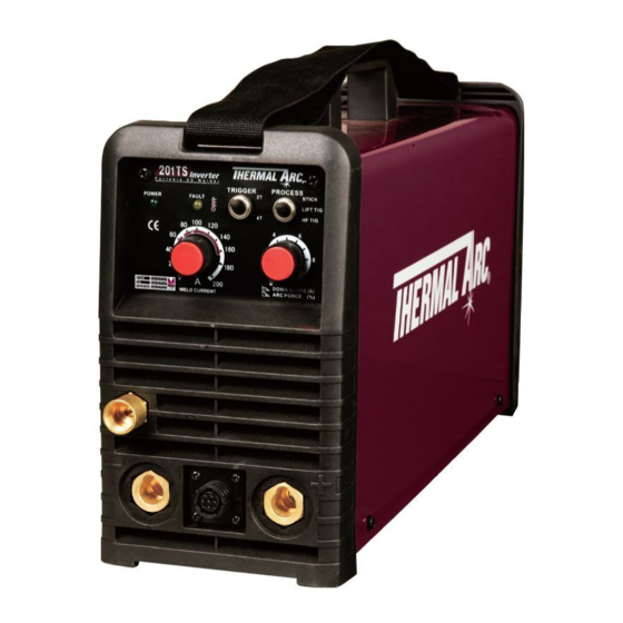
THERMAL ARC
InvERTER ARC WELdER
Revision: AC
Operating Features:
Issue Date: Dec. 03, 2012
®
Art # A-10144
Manual No.: 0-5148
50
Hz
60
50
Hz
60
Table of
Contents
Previous
Page
Next
Page
1
2
3
4
5
Advertisement
Table of Contents
Troubleshooting
TROUBLESHOOTING
43
Checking Unit Before Applying Power
44
Troubleshooting Circuit Diagram - 161STL
55
Troubleshooting Circuit Diagram - 201TS
57
Need help?
Do you have a question about the 201 TS and is the answer not in the manual?
Ask a question
Questions and answers
Related Manuals for Thermal Arc 201 TS
Welding System Thermal Arc 201 TS Operating Manual
Inverter arc welder (48 pages)
Welding System Thermal Arc ARCMASTER 200 TS Service Manual
Inverter arc welder (96 pages)
Welding System Thermal Arc 185 AC Service Manual
Inverter arc welders (122 pages)
Welding System Thermal Arc 200 AC Service Manual
Inverter arc welders (122 pages)
Welding System Thermal Arc 200 DC Service Manual
Inverter arc welders (122 pages)
Welding System Thermal Arc 202 AC/DC Operating Manual
Inverter welding machine (60 pages)
Welding System Thermal Arc ARCMASTER 200 S Service Manual
Inverter arc welder (88 pages)
Welding System Thermal Arc fabricator 210 Service Manual
Mig welding machine (98 pages)
Welding System Thermal Arc 211i Fabricator Operating Manual
(96 pages)
Welding System Thermal Arc 251 FABRICATOR Service Manual
Mig welding machine (106 pages)
Welding System Thermal Arc FABRICATOR 251 Operator's Manual
Mig welding machine (72 pages)
Welding System Thermal Arc Fabricator 251 Operating Manual
Mig welding machine (72 pages)
Welding System Thermal Arc 6045 EXCEL-ARC Operating Manual
Transformer-rectifier dc welder (20 pages)
Welding System Thermal Arc 281 FABRICATOR Service Manual
Mig welding machine (108 pages)
Welding System Thermal Arc Fabricator 281 Service Manual
Mig welding machine (108 pages)
Welding System Thermal Arc 250GTSWSE Operating Manual
Ac/dc cc/tig with sloper and repeat functions (35 pages)
This manual is also suitable for:
161 stl
Table of Contents
Save PDF
Print
Rename the bookmark
Delete bookmark?
Delete from my manuals?
Login
Sign In
OR
Sign in with Facebook
Sign in with Google
Upload manual
Upload from disk
Upload from URL


Need help?
Do you have a question about the 201 TS and is the answer not in the manual?
Questions and answers