
Related Manuals for Thermal Arc Fabricator 251


Summary of Contents for Thermal Arc Fabricator 251
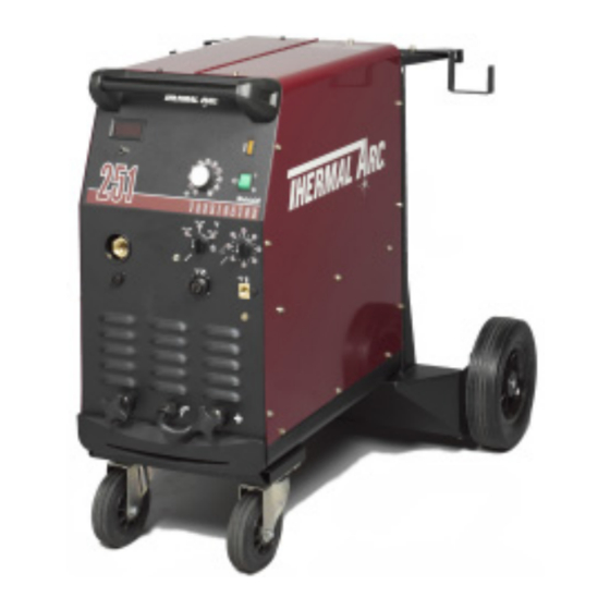
- Page 1 ® FABRICATOR MIG WELDING MACHINE Operating Manual Version No: AD.01 Issue Date: April 28, 2006 Manual No.: 0-4847 Operating Features: 60 60...
- Page 2 WE APPRECIATE YOUR BUSINESS! Congratulations on your new Thermal Arc product. We are proud to have you as our customer and will strive to provide you with the best service and reliability in the industry. This product is backed by our extensive warranty and world-wide service network.
- Page 3 While the information contained in this Manual represents the Manufacturer's best judgement, the Manufacturer assumes no liability for its use. Fabricator 251 MIG Welding Machine Instruction Manual Number 0-4847 for: Package System Part Number 100048D-002...
-
Page 4: Table Of Contents
TABLE OF CONTENTS SECTION 1: SAFETY INSTRUCTIONS AND WARNINGS ............1-1 1.01 Arc Welding Hazards ..................1-1 1.02 Principal Safety Standards ................1-4 1.03 Symbol Chart ....................1-5 1.04 Precautions De Securite En Soudage à L’arc ..........1-6 1.05 Dangers Relatifs au Soudage à L’arc .............. 1-6 1.06 Principales Normes De Securite .............. - Page 5 TABLE OF CONTENTS (continued) TABLE OF CONTENTS SECTION 4: OPERATION ................... 4-1 4.01 Power Supply Controls, Indicators and Features ..........4-1 4.02 Weld Mode Selector ..................4-6 4.03 TWECO Weldskill 300 AMP Weld Gun ............4-8 4.04 Installing A New Wire Conduit ................ 4-8 4.05 MIG Gun Maintenance ..................
-
Page 7: Safety Instructions And Warnings
FABRICATOR 251 SECTION 1: SAFETY INSTRUCTIONS AND WARNINGS WARNING PROTECT YOURSELF AND OTHERS FROM POSSIBLE SERIOUS INJURY OR DEATH. KEEP CHILDREN AWAY. PACEMAKER WEARERS KEEP AWAY UNTIL CONSULTING YOUR DOCTOR. DO NOT LOSE THESE INSTRUCTIONS. READ OPERATING/INSTRUCTION MANUAL BEFORE INSTALLING, OPERATING OR SERVICING THIS EQUIPMENT. - Page 8 FABRICATOR 251 3. Use protective screens or barriers to protect others from flash and glare; warn others not to watch the arc. WARNING 4. Wear protective clothing made from durable, flame-resistant material (wool and leather) and foot protection. WELDING can cause fire or explosion.
- Page 9 FABRICATOR 251 2. If used in a closed area, vent engine exhaust outside and away from any building air intakes. WARNING WARNING FLYING SPARKS AND HOT METAL can cause injury. Chipping and grinding cause flying metal. As welds cool, they can throw off slag.
-
Page 10: Principal Safety Standards
FABRICATOR 251 1.02 Principal Safety Standards Safety in Welding and Cutting, ANSI Standard Z49.1, from American WARNING Welding Society, 550 N.W. LeJeune Rd., Miami, FL 33126. Safety and Health Standards, OSHA 29 CFR 1910, from Superintendent STEAM AND PRESSURIZED HOT COOLANT can burn of Documents, U.S. -
Page 11: Symbol Chart
FABRICATOR 251 1.03 Symbol Chart Note that only some of these symbols will appear on your model. Wire Feed Function Single Phase Wire Feed Towards Workpiece With Three Phase Output Voltage Off. Three Phase Static Frequency Converter- Welding Gun Dangerous Voltage... -
Page 12: Precautions De Securite En Soudage À L'arc
FABRICATOR 251 1.04 Precautions De Securite En Soudage A L’arc MISE EN GARDE LE SOUDAGE A L’ARC EST DANGEREUX PROTEGEZ-VOUS, AINSI QUE LES AUTRES, CONTRE LES BLESSURES GRAVES POSSIBLES OU LA MORT. NE LAISSEZ PAS LES ENFANTS S’APPROCHER, NI LES PORTEURS DE STIMULATEUR CARDIAQUE (A MOINS QU’ILS N’AIENT CONSULTE UN MEDECIN). CONSERVEZ CES INSTRUCTIONS. - Page 13 FABRICATOR 251 AVERTISSEMENT AVERTISSEMENT LES VAPEURS ET LES FUMEES SONT DANGEREUSES LE RAYONNEMENT DE L’ARC PEUT BRÛLER LES YEUX POUR LA SANTE. ET LA PEAU; LE BRUIT PEUT ENDOMMAGER L’OUIE. Le soudage dégage des vapeurs et des fumées L’arc de soudage produit une chaleur et des rayons dangereuses à...
- Page 14 FABRICATOR 251 7. Ne soudez des tôles galvanisées ou plaquées au plomb ou au cadmium que si les zones à souder ont été grattées à fond, que si AVERTISSEMENT l’espace est bien ventilé; si nécessaire portez un respirateur à ad- duction d’air.
-
Page 15: Principales Normes De Securite
FABRICATOR 251 Les accumulateurs contiennent de l’électrolyte acide et 1. Utilisez l’équipement à l’extérieur dans des aires ouvertes et bien ventilées. dégagent des vapeurs explosives. 2. Si vous utilisez ces équipements dans un endroit confiné, les 1. Portez toujours un écran facial en travaillant sur un accumu-lateur. -
Page 16: Graphique De Symbole
FABRICATOR 251 1.07 Graphique de Symbole Seulement certains de ces symboles apparaîtront sur votre modèle. Déroulement du Fil Sous Tension Mono Phasé Alimentation du Fil Vers la Pièce de Fabrication Hors Tension Trois Phasé Hors Tension Tri-Phase Statique Soudage Torch de Tension dangereuse Fréquence Convertisseur... -
Page 17: Introduction
Include the Owner’s Manual number and equipment identification numbers. Electronic copies of this manual can also be downloaded at no charge in Acrobat PDF format by going to the Thermal Arc web site listed below and clicking on the Literature Library link: http://www.thermalarc.com April 28, 2006... -
Page 18: General Information
FABRICATOR 251 2.04 General Information 2.06 Protective Filter Lenses The Fabricator 251 is a semiautomatic Gas Metal Arc Protective filter lenses are provided to reduce the intensity Welder (GMAW-commonly MIG) with an integrated wire of radiation entering the eye thus filtering out harmful feed unit. -
Page 19: Duty Cycle
FABRICATOR 251 2.08 Duty Cycle The rated duty cycle of a welding Power Supply is the operating time it may be used at its rated output current without exceeding the temperature limits of the insulation of the component parts. To explain the ten minute duty cycle period the following example is used. - Page 20 FABRICATOR 251 Fabricator 251 Package System Part Number 100048D-002 Power Source Part Number 707237 Power Source Weight 227lb (103kg) 32” x 27-3/16” x 36-3/4” Power Source Dimensions HxWxD (813 x 691 x 933mm) (including wheels and cylinder carrier) Nominal Input Voltage...
-
Page 21: Included Items
FABRICATOR 251 2.10 Included Items Fabricator 251 Package System Contents Factory Fitted Wheeling Kit Factory Fitted Dual Cylinder Rack Factory Fitted Primary Power Cable 8AWG, 10ft (3m) with Plug NEMA 6-50P Work Lead 10ft (3m) Cable Stowage Hooks Regulator/Flow Meter – Argon Mix Gases Tweco Weldskill MIG Gun 300 Amp, 15ft (4.5m) - Page 22 FABRICATOR 251 April 28, 2006...
-
Page 23: Installation
In areas, free from moisture and dust. 3.01 Environment In areas, free from oil, steam and corrosive gases. The Fabricator 251 is NOT designed for use in In areas, not subjected to abnormal vibration or shock. environments with increased hazard of electric shock. -
Page 24: Mains Supply Voltage Requirements
3.05 Alternative Mains Supply Voltages WARNING The Fabricator 251 input power supply lead should be replaced with leads as specified in Table 3-2 when the Fabricators input power supply voltage is changed. The Power Supply is suitable for use on the following input power supply voltages:... - Page 25 3. Remove the blue wires from the current location and Insert them into the new voltage location. Secure by tighten- ing the set screw onto the uninsulated portion of the wires. Secure the other voltage set screw as well. 208V connection 230V connection Art # A-07332 Figure 3-1: Voltage Selections for Fabricator 251 (Wired for 230V) April 28, 2006...
-
Page 26: Quick Setup
FABRICATOR 251 7. Fit the electrode wire spool to the wire reel hub 3.06 Quick Setup located behind the electrode wire compartment door. CAUTION 8. Fit the TWECO Weldskill MIG gun and trigger wires through/to the front of the unit. - Page 27 FABRICATOR 251 Shielding Regulator and Flow Meter “Cracking” Shielding Shielding Shielding Art # A-07278 Stowage Hook Gas Hose Figure 3-2 Gas Cylinder Installation April 28, 2006...
- Page 28 FABRICATOR 251 Adjusting Regulator Adjust control knob of regulator to the required flow rate, indicated on gauge dial. (Refer to Figure 3-3) The gas flow rate should be adequate to cover the weld zone to stop weld porosity. Excessive gas flow rates may cause turbulence and weld porosity.
-
Page 29: Attaching The Gun And Cable Assembly To The Power Source
Assembly to the Power Source The Fabricator 251 is supplied with a Tweco Weldskill 300 AMP air-cooled gun. The Weldskill gun is designed with an ergonomic handle and fewer parts to cause performance problems. The Weldskill gun uses standard readily available Tweco Weldskill consumable parts. - Page 30 FABRICATOR 251 Front Panel Access Hole Art # 0-7148 Trigger Receptacle Figure 3-5: Route Gun Cable Through Front Panel Access Hole and Connect Trigger Loosen Thumbscrew Art # A-07149 Tighten Thumbscrew Figure 3-6: Mount Gun Cable to Adapter Socket April 28, 2006...
-
Page 31: Input And Output Wire Guide Installation
Input Wire Guide Output Wire Guide Figure 3-7: Wire Guide Installation Installation of all styles of feed rolls for the Fabricator 251 are identical. 3.10 Selection and Installation of Feedrolls WARNING A Feedroll consists of two different sized grooves. As... -
Page 32: Installing Wire Spool
FABRICATOR 251 3.11 Installing Wire Spool As delivered from the factory, the unit is set for a 33/44 lb. or 12" (300mm) spool. Installation of wire spool 1. Remove Wire Spool Hub Nut by turning counter clock wise (to the left). -
Page 33: Inserting Wire Into The Feedhead
FABRICATOR 251 3.12 Inserting Wire into the Feedhead WARNING ELECTRIC SHOCK CAN KILL! Make certain the input power is disconnected from the power supply before proceeding. Do not reattach the input power until told to do so in these instructions. -
Page 34: Wirefeeder Drive Roller Pressure Adjustment
FABRICATOR 251 Wheel Brake Hex Head Bolt Pressure Adjustment Device Art # A-07162 Spool Hub Nut Figure 3-12: Wire Installed 3.13 Wirefeeder Drive Roller Pressure Adjustment The roller on the swing arm applies pressure to the grooved roller via an adjustable tension devise. The Tension Adjuster should be set to a minimum pressure that will provide satisfactory wire feed without slippage. -
Page 35: Spool Gun Attachment
FABRICATOR 251 3.15 Spool Gun Attachment A spool gun can readily be used with the Fabricator 251 power supply. 1. Attach appropriate input gas to the Spool Gun input gas connection on the rear of the unit. (Refer to Figure. 3- 2. -
Page 36: Polarity Changeover
FABRICATOR 251 3.16 Polarity Changeover WARNING ELECTRIC SHOCK CAN KILL! Make certain the input power is disconnected from the power supply before proceeding. Do not reattach the input power until told to do so in these instructions. The output terminals are located on the front panel of the welding power source. - Page 37 FABRICATOR 251 Work Lead Connected for D.C. Electrode Negative (DCEN) Welding Art # A-07164 Figure 3-15: Polarity Connections for DCEN Changing polarity process. a. Locate the two terminal knobs at the front of the machine. Refer to Figures 3-14 and 3-15.
- Page 38 FABRICATOR 251 NOTES: 3-16 April 28, 2006...
-
Page 39: Operation
FABRICATOR 251 SECTION 4: OPERATION WARNING DO NOT TOUCH the electrode wire while it is being fed through the system. The electrode wire will be at welding voltage potential. 4.01 Power Supply Controls, Indicators and Features Thermal Overload Indicator Digital Display... - Page 40 On / Standby Power Switch The indicator light is provided to indicate when the Fabricator 251 is connected to the Input Power Supply Voltage. With the switch in the Standby position, the auxiliary power and the fan are turned off and the switch is illuminated.
- Page 41 FABRICATOR 251 Digital AMP Reading to IPM Conversion STEEL Current (Amps) Art # A-07451 Figure 4-3: Steel - AMP to IPM Conversion STAINLESS STEEL Current (Amps) Art # A-07452 Figure 4-4: Stainless Steel - AMP to IPM Conversion April 28, 2006...
- Page 42 FABRICATOR 251 ALUMINUM Current (Amps) Art # A-07453 Figure 4-5: Aluminum - AMP to IPM Conversion Thermal Overload The critical components for thermal protection are the rectifier stack and the transformer, which are fitted with thermal overload cut out devices. If the overload is activated then the machine should be left to cool for approxi- mately 15 minutes before resuming welding.
- Page 43 The Spool Gun Interface 10 pin connector is used to the bottom of the unit are shown without the terminal connect a spool gun to the Fabricator 251 (refer to knob. Both knobs must be firmly secured before at- Figure 4-4 and Table 4-1).
-
Page 44: Weld Mode Selector
FABRICATOR 251 4.02 Weld Mode Selector The Weld Mode Selector switch selects the method of welding mode. WELD WELD DWELL DWELL WELD MODE WELD MODE (STITCH) (STITCH) (SPOT / STITCH) (SPOT / STITCH) STITCH STITCH SPOT SPOT 4T 4T 2T 2T... - Page 45 FABRICATOR 251 STITCH: Dwell Stitch This mode of welding is used to weld two or more DWELL (STITCH) CONTROL KNOB components together with a stitch weld. The WELD When the Weld Mode control is in the Stitch position, the (Spot/Stitch) shaft controls the welding or ‘ON’ time Dwell (Stitch) knob controls the length of the non-weld and the "DWELL (Stitch)"...
-
Page 46: Tweco Weldskill 300 Amp Weld Gun
4.03 TWECO Weldskill 300 AMP Weld Gun The TWECO Weldskill 300 AMP gun fitted to the FABRICATOR 251 offers robust construction, unparalleled reliability and easy replacement of consumable parts. The TWECO Weldskill gun has an operating capacity in excess of the capacity of the FABRICATOR and can be expected to give trouble free service. -
Page 47: Mig Gun Maintenance
FABRICATOR 251 When the conduit stop meets the end of the connector plug and the new raw end extends through the end of the conductor tube on the welding gun, tighten the Allen screw in the connector plug onto the conduit to prevent its backward movement. -
Page 48: Basic Welding Technique
Setting of the Power Supply The setting of the Fabricator 251 requires some practice by the operator, the welding Power Supply having two control settings that have to balance. These are the Wire Speed control and the Voltage Control switches. The welding current is determined by the Wire Speed control, the current will increase with increased Wire Speed, resulting in a shorter arc. - Page 49 FABRICATOR 251 Distance from the MIG Gun Nozzle to the Work Piece The electrode stick out from the MIG gun nozzle should be between 5/64" (2.0mm) to 13/64" (5.0mm). This distance may vary depending on the type of joint that is being welded.
-
Page 50: Stitch Welding Operation
SPOT WELDING NOZZLES for consistent spot welding operations. Refer to the TYPE NO.4 400 AMP Spot Welding Nozzle table. The Fabricator 251 will operate effectively using .030” (0.8mm) electrode wire when spot welding. Penetration depth is limited Flat Arc Spot 24A-62-FAS 1240-1520 (5/8"... -
Page 51: Gas Selection For Gas Metal Arc Welding
FABRICATOR 251 4.09 Gas Selection for Gas Metal Arc Welding Suggested Base Plate Filler Transfer Welding Metal Type Shielding Comments Thickness Metal Mode Positions Carbon Greater than 22 ER70S-X Short High welding speeds. Good 100% CO Steel gauge (.030”) Circuit Position penetration and pool control. -
Page 52: Welding Setting Selection Guide
FABRICATOR 251 4.10 Welding Setting Selection Guide Shielding Gas Wire Size Material Type Wire Type (Diameter) and Flow Rate .035” (0.9mm) 100% CO 25cfh .045” (1.2mm) .023” (0.6mm) .030” (0.8mm) 75% Ar 25% ,25cfh Solid .035” (0.9mm) (or hard) Steel .045”... - Page 53 FABRICATOR 251 Coarse Voltage THICKNESS Fine Voltage Step Wire Coarse Fine Speed Voltage Voltage 22 ga. (0.8mm) 18 ga. (1.2mm) 16 ga. (1.6mm) 1/8” (3.2mm) 1/4” (6.4mm) 3/8” (9.5mm) 1/2” (12.7mm) 5/8” (15.9mm) 7.25 1.75 4.25 2.25 5.25 8.25 3.25 5.75...
- Page 54 FABRICATOR 251 NOTES 4-16 April 28, 2006...
-
Page 55: Maintenance & Troubleshooting
SECTION 5: MAINTENANCE & TROUBLESHOOTING 5.01 Routine Maintenance & Inspection The only routine maintenance required for the Fabricator 251 is a thorough cleaning and inspection, with the fre- quency depending on the usage and the operating environment. WARNING Disconnect the Fabricator from the Input power supply voltage before disassembling. - Page 56 FABRICATOR 251 Maintain more often Warning! if used under severe Disconnect input power before maintaining. conditions Each Use Visual check of torch Visual check of Consumable parts regulator and pressure Weekly Visually inspect the torch Visually inspect the body and consumables cables and leads.
-
Page 57: Basic Troubleshooting
The basic level of troubleshooting is that which can be performed without special equipment or knowledge, and without removing the covers from the Power Supply. If major components are faulty, then the Power Supply should be returned to an Accredited Thermal Arc Service Agent for repair. - Page 58 FABRICATOR 251 WARNING Disengage the drive roll when testing for gas flow by ear. 2. Inconsistent wire feed FAULT CAUSE REMEDY 1. Wire spool brake is a. Feed roller driven by motor in the cabinet will slip. too tight. 2. Wire spool brake is a.
-
Page 59: Welding Problems
FABRICATOR 251 5.04 Welding Problems FAULT CAUSE REMEDY 1. Welding arc voltage a. Reduce voltage by reducing the voltage too high. selection switch position or increase the wire feed speed. A. Undercut 2. Incorrect torch a. Adjust angle angle 3. Excessive heat a. - Page 60 6. Weld speed too fast a. Reduce weld speed. 1. Faulty rectifier unit a. Have an Accredited THERMAL ARC Service Agent to test then replace the faulty component. B. Cold weld puddle 2. Loose welding cable a.
-
Page 61: Power Supply Problems
B. Mains supply voltage is ON. 1. Primary fuse is blown. a. Replace primary fuse. Indicator light is not lit and 2. Broken connection in a. Have an Accredited Thermal Arc welding arc can not be primary circuit. Service Agent check primary established. - Page 62 FABRICATOR 251 NOTES April 28, 2006...
-
Page 63: Appendix 1: Optional Accessories And Consumables
FABRICATOR 251 APPENDIX 1: OPTIONAL ACCESSORIES AND CONSUMABLES For Tweco/Victor Inquiries and Orders: Call 1-800-318-6819 Consumable Parts Management Group GUNS Tweco® WeldSkill 15ft 43340 Gun assembly with 15ft cable (supplied with package), 300 Amp @ 30% Tweco® No. 4 12ft... -
Page 64: Appendix 2: Power Supply Circuit Diagram
FABRICATOR 251 APPENDIX 2: POWER SUPPLY CIRCUIT DIAGRAM • Note the model and part number shown on the equipment nameplate 4 BLUE COARSE 4A BLUE 8&8A BRN FABRICATOR 251 (10) 8 BRN 9&9A BLK (12) (11) 9 BLK 10&10A RED... - Page 65 FABRICATOR 251 SWITCH 2 COARSE SWITCH 3 FI NE SWI TCH POSITI ON POSITI ON 10 12 10 12 Bridge Recti fier POSITIVE OUTPUT Induct or TERMINAL PLUGSOCKET 21 ORN X1/6 PCB 4 22 VIO Varis tor X1/5 + C1-C4...
-
Page 66: Appendix 3: Feedroll Kits
FABRICATOR 251 APPENDIX 3: FEEDROLL KITS DRIVE ROLL KITS (#375980-Series) 2 ROLL Style 1 Style 2 Style 3 Style 4 Style 5 Style 6 Double Smooth Double Flat Flat Knurled Double Cog Double "U" "V" Knurled "V" Double Double Double Smooth... -
Page 68: Limited Warranty
No employee, agent, or representative of Thermal Arc is authorized to change this warranty in any way or grant any other warranty, and Thermal Arc shall not be bound by any such attempt. -
Page 69: Warranty Schedule
WARRANTY SCHEDULE This information applies to Thermal Arc products that were purchased in the USA and Canada. April 2006 ENGINE DRIVEN WELDERS ARRANTY ERIOD ABOR Scout, Raider, Explorer Original Main Power Stators and Inductors .................. 3 years 3 years Original Main Power Rectifiers, Control P.C. Boards ..............3 years... -
Page 71: Global Customer Service Contact Information
GLOBAL CUSTOMER SERVICE CONTACT INFORMATION Thermadyne USA Thermadyne Asia Sdn Bhd 2800 Airport Road Lot 151, Jalan Industri 3/5A Denton, Tx 76207 USA Rawang Integrated Industrial Park - Jln Batu Arang Telephone: (940) 566-2000 48000 Rawang Selangor Darul Ehsan West Malaysia 800-426-1888 Telephone: 603+ 6092 2988 Fax: 800-535-0557... - Page 72 World Headquarters Thermadyne Holdings Corporation Suite 300, 16052 Swingley Ridge Road St. Louis, MO 63017 Telephone: (636) 728-3000 Fascimile: (636) 728-3010 Email: sales@thermalarc.com www.thermalarc.com...
Need help?
Do you have a question about the Fabricator 251 and is the answer not in the manual?
Questions and answers