
Related Manuals for Thermal Arc ARCMASTER 200 S


Summary of Contents for Thermal Arc ARCMASTER 200 S
-
Page 1: Service Manual
200 S ® ARCMASTER INVERTER ARC WELDER Art # A-06795 Service Manual Version No: AA.01 Issue Date: May 22, 2006 Manual No.: 0-4940B Operating Features:... - Page 3 While the information contained in this Manual represents the Manufacturer's best judgement, the Manufacturer assumes no liability for its use. ArcMaster 200 S Inverter Arc Welder Service Manual Number 0-4940B for: Part Number 10-3084 Published by: Thermadyne Industries, Inc.
-
Page 4: Table Of Contents
CONTENTS 1 SAFETY INSTRUCTIONS AND WARNINGS 1 Arc Welding Hazards................1–1 2 PRINCIPAL SAFETY STANDARDS . - Page 5 11 ADVANCED TROUBLESHOOTING 1 System-Level Fault Isolation ..............11–1 1.
-
Page 7: Safety Instructions And Warnings
ARCMASTER 200 S SECTION 1: SAFETY INSTRUCTIONS AND WARNINGS WARNING PROTECT YOURSELF AND OTHERS FROM POSSIBLE SERIOUS INJURY OR DEATH. KEEP CHILDREN AWAY. PACEMAKER WEARERS KEEP AWAY UNTIL CONSULTING YOUR DOCTOR. DO NOT LOSE THESE INSTRUCTIONS. READ OPERATING/INSTRUCTION MANUAL BEFORE INSTALLING, OPERATING OR SERVICING THIS EQUIPMENT. - Page 8 ARCMASTER 200 S 3. Use protective screens or barriers to protect others from flash and glare; warn others not to watch the arc. WARNING 4. Wear protective clothing made from durable, flame-resistant material (wool and leather) and foot protection. WELDING can cause fire or explosion.
- Page 9 ARCMASTER 200 S 2. If used in a closed area, vent engine exhaust outside and away from any building air intakes. WARNING WARNING FLYING SPARKS AND HOT METAL can cause injury. Chipping and grinding cause flying metal. As welds cool, they can throw off slag.
-
Page 10: Principal Safety Standards
ARCMASTER 200 S 1.02 Principal Safety Standards Safety in Welding and Cutting, ANSI Standard Z49.1, from American WARNING Welding Society, 550 N.W. LeJeune Rd., Miami, FL 33126. Safety and Health Standards, OSHA 29 CFR 1910, from Superintendent STEAM AND PRESSURIZED HOT COOLANT can burn of Documents, U.S. -
Page 11: Precautions De Securite En Soundage A L'arc
ARCMASTER 200 S 1.03 Precautions de Securite en Soudage à l’Arc MISE EN GARDE LE SOUDAGE A L’ARC EST DANGEREUX PROTEGEZ-VOUS, AINSI QUE LES AUTRES, CONTRE LES BLESSURES GRAVES POSSIBLES OU LA MORT. NE LAISSEZ PAS LES ENFANTS S’APPROCHER, NI LES PORTEURS DE STIMULATEUR CARDIAQUE (A MOINS QU’ILS N’AIENT CONSULTE UN MEDECIN). CONSERVEZ CES INSTRUCTIONS. - Page 12 ARCMASTER 200 S AVERTISSEMENT AVERTISSEMENT LES VAPEURS ET LES FUMEES SONT DANGEREUSES LE RAYONNEMENT DE L’ARC PEUT BRÛLER LES YEUX POUR LA SANTE. ET LA PEAU; LE BRUIT PEUT ENDOMMAGER L’OUIE. Le soudage dégage des vapeurs et des fumées L’arc de soudage produit une chaleur et des rayons dangereuses à...
- Page 13 ARCMASTER 200 S 7. Ne soudez des tôles galvanisées ou plaquées au plomb ou au cadmium que si les zones à souder ont été grattées à fond, que si AVERTISSEMENT l’espace est bien ventilé; si nécessaire portez un respirateur à ad- duction d’air.
-
Page 14: Principales Normes De Securite
ARCMASTER 200 S Les accumulateurs contiennent de l’électrolyte acide et 1. Utilisez l’équipement à l’extérieur dans des aires ouvertes et bien ventilées. dégagent des vapeurs explosives. 2. Si vous utilisez ces équipements dans un endroit confiné, les 1. Portez toujours un écran facial en travaillant sur un accumu-lateur. -
Page 15: Declaration Of Conformity
ARCMASTER 200 S 1.06 Declaration Of Conformity Manufacturer: Thermadyne Corporation Address: 82 Benning Street West Lebanon, New Hampshire 03784 The equipment described in this manual conforms to all applicable aspects and regulations of the ‘Low Voltage Directive’ (European Council Directive 73/23/EEC as amended by Council Directive 93/68/EEC) and to the National legislation for the enforcement of this Directive. - Page 16 ARCMASTER 200 S 1-10 May 22, 2006...
-
Page 17: Introduction
Electronic copies of this manual can also be down- loaded at no charge in Acrobat PDF format by going to the Thermal Arc web site listed below and clicking on the Literature Library link: http://www.thermalarc.com Equipment Identification The unit’s identification number (specification or... -
Page 18: Symbol Chart
200S INTRODUCTION Symbol Chart Note that only some of these symbols will appear on your model. STICK Amperage (Shielded Metal Arc SMAW) Pulse Current Function Voltage Spot Time (GTAW) Hertz (frequency) Remote Control Seconds (Panel/Remote) Remote Function Percent Arc Control (SMAW) DC (Direct Current) Gas Post-Flow AC (Alternating Current) -
Page 19: Description
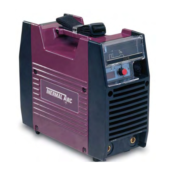
200S INTRODUCTION Description The Thermal Arc Model 200S is a self contained single-phase DC arc welding power sources with Con- stant Current (CC) output characteristics. This unit is equipped with a Digital Volt/Amperage Meter and lift arc starter, for use with Gas Tungsten Arc Welding (GTAW) and Shielded Metal Arc Welding (SMAW) pro- cesses. -
Page 20: Transporting Methods
200S INTRODUCTION Transporting Methods These units are equipped with a handle for carrying purposes. WARNING ELECTRIC SHOCK can kill. DO NOT TOUCH live electrical parts. Disconnect input power conductors from de-energized supply line before moving the welding power source. WARNING FALLING EQUIPMENT can cause serious per- sonal injury and equipment damage. -
Page 21: Installation
WARNING Thermal Arc advises that this equipment be electri- Do not connect an input (BROWN or BLUE) con- cally connected by a qualified electrician. ductor to the ground terminal. -
Page 22: Input Power
The ARC MASTER 200S is designed for use with a generator as an input power source. Contact an source (Based on Article 630, National Electrical accredited Thermal Arc service agent for the Code). proper sizing and set-up recommendations of a generator power source system. -
Page 23: Specifications
200S INSTALLATION Thermal Arc continuously strives to produce the NOTE best product possible and therefore reserves the Due to variations that can occur in manufactured right to change, improve or revise the specifica- products, claimed performance, voltages, ratings, tions or design of this or any product without prior all capacities, measurements, dimensions and notice. - Page 24 200S INSTALLATION PAGE LEFT INTENTIONALLY BLANK 3 – 4...
-
Page 25: Operator Control
OPERATOR CONTROL 1. Control Knob: OPERATOR CONTROL ARC MASTER 200S This control sets the selected weld parameter, Controls rotating it clockwise increases the parameter that is indicated on the digital meter. Pushing the knob inward displays the actual welding voltage. 2. -
Page 26: Weld Parameter Descriptions For Arc Master 200S
200S OPERATOR CONTROL Weld Parameter Descriptions 3. Positive Terminal: Welding current flows from the Power Source for ARC MASTER 200S via heavy duty Dinse type terminal (Size 50mm) It is essential, however, that the male plug is inserted and turned securely to achieve a sound electrical connection. -
Page 27: Weld Parameters For Arc Master 200S
200S OPERATOR CONTROL Weld Parameters for ARC Feature Description MASTER 200S Reduces the OCV when the power supply is not in use. Eliminates the need for add on voltage reducers and 3.1 Weld Parameters Voltage has no effect on arc starting. ... - Page 28 200S OPERATOR CONTROL 4 – 4...
-
Page 29: Set-Up For Smaw (Stick) And Gtaw (Tig)
SET-UP FOR SMAW (STICK) AND GTAW (TIG) SET-UP FOR SMAW (STICK) AND GTAW (TIG) Conventional operating procedures apply when using the Welding Power Source, i.e. connect work lead directly to work piece and electrode lead is used to hold electrode. Wide safety margins pro- vided by the coil design ensure that the Welding Power Source will withstand short-term overload without adverse effects. -
Page 30: Sequence Of Operation
SEQUENCE OF OPERATION Stick Welding NOTE SEQUENCE OF OPERATION Scroll Buttons are used to select the parameters to be set. The LED’s show which function is being Connect work lead to negative terminal. adjusted on the weld sequence graph. Refer to the ... -
Page 31: Routine Maintenance
ROUTINE MAINTENANCE The only routine maintenance required for the ROUTINE MAINTENANCE power supply is a thorough cleaning and inspec- tion, with the frequency depending on the usage and the operating environment. WARNING Disconnect primary power at the source before opening the enclosure. Wait at least two minutes before opening the enclosure to allow the primary capacitors to discharge. - Page 32 6 Months Bring the unit to an authorized Thermal Arc Service Center to remove any accumulated dirt and dust from the interior. This may need to be done more frequently under exceptionally dirty conditions.
-
Page 33: Basic Troubleshooting
WARNING There are extremely dangerous voltages and power levels present inside this product. Do not attempt to open or repair unless you are an Accredited Thermal Arc Service Agent and you have had training in power measurements and troubleshooting techniques. -
Page 34: Stick Welding Problems
200S BASIC TROUBLESHOOTING Description Possible Cause Remedy Inadequate shielding gas. Increase gas flow or check gas line for gas 9 Poor weld finish. flow problems. 10 Arc flutters during TIG A Tungsten electrode is too large for the A Select the right size electrode. Refer to welding. - Page 35 200S BASIC TROUBLESHOOTING Description Possible Cause Remedy 4 Portions of the weld run A Small electrodes used on heavy cold A Use larger electrodes and pre-heat the do not fuse to the plate. plate. surface of the metal or B Welding current is too low. B Increase welding current.
-
Page 36: Power Source Problems
A Switch ON the Primary supply voltage. be established. switched ON. B Switch ON the Welding Power Source. B The Welding Power Source switch is C Have an Accredited Thermal Arc Service switched OFF. Agent repair the connection. C Loose connections internally. Defective control circuit. -
Page 37: Voltage Reduction Device (Vrd)
In addition to the above tests and specifically in relation to the VRD fitted to this machine, the fol- lowing periodic tests should also be conducted by an accredited Thermal Arc service agent. Description IEC 60974-1 Requirements VRD Open Circuit Voltage Less than 20V; at Vin=230V... -
Page 38: Switching Vrd On/Off
200S VOLTAGE REDUCTION DEVICE (VRD) Switching VRD On/Off CAUTION Do not pull back the front panel with excessive Switch the machine Off. force as this will unplug control PCB. Plugging the control PCB back into the front panel controls can A) Remove the clear plastic cover from the control only be achieved by removing the side covers. -
Page 39: Power Source Error Code
Fan operates at max B Fan ceases to operate. B Have an Accredited about 1 second. speed.E01 resets when Thermal Arc Service Agent TH1 decreases to 70oC investigate. for about 30 seconds. C Air flow is restricted by C Unblock vents then let vents being blocked. - Page 40 200S POWER SOURCE ERROR CODE PAGE LEFT INTENTIONALLY BLANK 10 – 2...
-
Page 41: Advanced Troubleshooting
CAUTION faulty subassembly should then be returned to The capacitors inside the power supply will slowly Thermal Arc through established procedures. discharged after you turn off the switch of the power supply or the switch at the breaker box (dis- tribution panel). - Page 42 200S ADVANCED TROUBLESHOOTING 3) Loosen the screws on the front panel and the 5) Remove the side panel. rear panel by turning them approximately two turns CCW. NOTE DO NOT remove the screws completely. Figure 11-5: Remove side panel 6) Remove protection cover sheet by removing the plastic tabs.
-
Page 43: Verification And Remedy To The Indicated Error Codes
200S ADVANCED TROUBLESHOOTING Verification and Remedy to c) Verify the operation of the cooling fan, FAN1, and replace it if necessary. the Indicated Error Codes Verify the condition of FAN1. Verify that there are no broken or cracked fan blades and that NOTE FAN1 is not producing any abnormal sounds. -
Page 44: E03 "Primary Over-Current Failure
200S ADVANCED TROUBLESHOOTING c) Verify the operation of the cooling fan, FAN1, 2.4 E94 “Thermistor malfunction” and replace it if necessary. Verify the condition of FAN1. Verify that there Cause are no broken or cracked fan blades and that Thermistors for detecting temperature of internal FAN1 is not producing any abnormal sounds. -
Page 45: Verification And Remedy To Failures Without Indication Codes
200S ADVANCED TROUBLESHOOTING Verification and Remedy to 3.2 “No weld output” Failures without Indication Cause Codes Occurs when the remote connector (CON1) or associated circuitry is defective, damaged, or the Refer to Note on Section 11.02. TIG torch cable is defective. 3.1 “Cooling Fan (FAN1) Failure”... -
Page 46: Operating Panel Failure" (Led's Do Not Light Properly Or Welding Setting Cannot Be Establish.)
200S ADVANCED TROUBLESHOOTING Fault Isolation Tests below. Replace any defective components found. 1) Secondary diode (D2-D3) 4.1 Preparation Verification. Refer to the page 11-12. The following initial conditions must be met prior to Replacement. Refer to the page 12-15. starting any of the procedures in this section. -
Page 47: Verification Of The Power Input Circuitry
200S ADVANCED TROUBLESHOOTING Using an AC voltmeter, measure between the Verification of the Power points U2 and V2 on the input switch, S1. Input Circuitry The location of points U2 and V2 on switch S1are indicated in Figure 11-7. CAUTION 4) If this voltage is out of the operating range, Before performing any portion of the procedure... -
Page 48: Verification Of The Power Supply Voltage
200S ADVANCED TROUBLESHOOTING PCB4 (WK-5449) Figure 11-9: The check points TB1(P) and TB2(N) Figure 11-10: Checkpoints TP0-TP3 on PCB6 7) After the replacement of D1, if the above voltage is still abnormal, replace PCB1 (WK-5713). Test Point Reference ACCEPTABLE PCB6 PCB6 VALUE 5.2 Verification of the Power Sup-... - Page 49 200S ADVANCED TROUBLESHOOTING below, make certain the unit is placed in the initial Voltage set up condition as described in section 11.4.1 FAN1 measurement. Remedy "Preparation" on page 11-6. Status (1PIN-2PIN of CN2 on PCB1) Replace the Case 4 Inactive DC 18 ~ 25V FAN1.Refer to the 1) Verify the condition of the cooling fan, FAN1,...
-
Page 50: Verification Of The Primary Diode (D1)
200S ADVANCED TROUBLESHOOTING 5.4 Verification of the primary Diode (D1) CAUTION Before performing any portion of the procedure below, make certain the unit is placed in the initial set up condition as described in section 11.4.1 "Preparation" on page 11-6. 1) Verify the characteristic of the primary diode, D1, using a diode tester. -
Page 51: Verification Of The Secondary Diode (D2, D3)
200S ADVANCED TROUBLESHOOTING 5.5 Verification of the secondary 5.6 Verification of the primary Diode (D2, D3) IGBT (Q1A-Q4C) CAUTION CAUTION Before performing any portion of the procedure Before performing any portion of the procedure below, make certain the unit is placed in the initial below, make certain the unit is placed in the initial set up condition as described in section 11.4.1 set up condition as described in section 11.4.1... -
Page 52: Verification Of No-Load Voltage (Ocv)
200S ADVANCED TROUBLESHOOTING 5.7 Verification of No-load Volt- age (OCV) CAUTION Before performing any portion of the procedure below, make certain the unit is placed in the initial set up condition as described at the beginning of an above section “1.Preparation”. Refer to section 11.4-1. -
Page 53: Maintenance
MAINTENANCE MAINTENANCE Subsystem Test and Replacement Procedures 1.1 Preparation This section provides specific procedures for verifying the operation and replacement of each subsystem within the power supply. Before undertaking any of these procedures, eliminate the obvious first-visually inspect the suspect sub- system for physical damage, overheating, and loose connections. - Page 54 200S MAINTENANCE REFERENCE DWG NO. PARTS NAME PART NO. PAGE Capacitor 12-8 10-6510 C101-C102 Capacitor 12-17 W7001622 C103 Capacitor 12-20 W7001621 Capacitor 12-21 W7001620 FCH1 Reactor 12-14 W7001502 L101 Ring Core 12-20 10-5230 L102 Reactor 12-20 W7001625 L103 Reactor 12-20 W7001624 Resistor 12-21...
- Page 55 200S MAINTENANCE REFERENCE DWG NO. PARTS NAME PART NO. PAGE 12-18 10-6627 CON1 Remote Receptacle 12-15 10-5003 Hall Current Trans 12-5 W7001481 Primary Diode 12-14 10-6629 Secondary Diode 12-14 10-6629 Secondary Diode 12-16 10-5227 FAN1 Cooling Fan 12-16 W7001453 Switch 12-19 10-5228 Primary Thermistor...
-
Page 56: Service Tools
200S MAINTENANCE Service Tools 2.1 Tools and parts The tools and parts to be used for maintenance are shown by icons. Philips Head Long Nose Soldering Copper Silicon Spanner Snap Band Compound Screwdriver (solder) Pliers 2.2 Notes of disassembly and assembly NOTE When removing the locking type connectors and board supporters, disengage the locking mechanism first and then disconnect them. -
Page 57: Replacement Procedure
200S MAINTENANCE Replacement Procedure 3.1 PCB1 (WK-5713) and Primary Diode D1 1) Remove the Side Panel. [See section “11.1-1”] 2) Remove the L102. [See section “12.3-16“] 3) Remove the screw and three cables. Cut the snap band. 4) Remove the terminal and Disconnect the three connectors CN1 (PCB4), CN101, 103 (PCB1). CN103 CN101 5) Remove the one terminal. - Page 58 200S MAINTENANCE 6) Remove the four screws and the Front Panel. 7) Remove the four screws and the Rear Panel. 8) Remove the four screws and the two cables. Disconnect the eight connectors CN1-8 on the PCB1. CN4 CN5 CN6 CN8 CN7 12 –...
- Page 59 200S MAINTENANCE 9) Remove the four screws and Remove the PCB1 unit. 10) Remove the Primary Diode D1 with the soldering iron from the PCB1. Before installing a new diode, apply a uniform coat of silicone compound (Shinetsu Silicone G-747 or equivalent) on the base.
-
Page 60: Pcb2 (Wk-5714), Capacitor C1 And Resistor R1
200S MAINTENANCE 3.2 PCB2 (WK-5714), Capacitor C1 and Resistor R1 1) Remove the Side Panel. [See section “11.1-1”] 2) Remove the PCB1 and D1. [See section “12.3-1”] 3) Remove the PCB6 and PCB7. [See section “12.3-6, 3-7”] 4) Remove the screw and the cable. 5) Remove the eight screws and the PCB2 unit. -
Page 61: Pcb3 (Wk-5609) And T1 "Transformer
200S MAINTENANCE 3.3 PCB3 (WK-5609) and T1 “Transformer” 1) Remove the Side Panel. [See section”11.1-1”] 2) Remove the CT1. [See section “12.3-10”] 3) Cut the snap band and Remove the cables. Disconnect the three connectors CN1-3 on the PCB3. Remove the three screws and the three cables. Remove the terminal. 4) Remove the 11 screws and PCB3 unit. -
Page 62: Pcb4 (Wk-5449)
200S MAINTENANCE 3.4 PCB4 (WK-5449) 1) Remove the Side Panel. [See section “11.1-1”] 2) Remove the Protection Cover. 3) Remove the Knob Cap. Holding the Knob down, loosen the screw and remove the Knob. 4) Disconnect the two connectors CN1,3 on the PCB4. Remove the four screws. Pull out the operation panel and bring it down. -
Page 63: Pcb5 (Wk-5448)
200S MAINTENANCE 5) Remove the four screws. Remove the PCB4. 3.5 PCB5 (WK-5448) 1) Remove the Side Panel. [See section “11.1-1”] 2) Remove the PCB4. [See section “12.3-4”] 3) Remove the three latches of Front Control Cover and then remove the PCB5. ... -
Page 64: Pcb6 (Wk-5460) And Q1A-Q2C "Primary Igbt
200S MAINTENANCE 3.6 PCB6 (WK-5460) and Q1A-Q2C “Primary IGBT” 1) Remove the Side Panel. [See section “11.1-1”] 2) Remove the four screws and two IGBT Spring Clips. Remove the cables from edge holder. 3) Disconnect the connector CN1 on the PCB6. Cut the lead of the Q1A-Q2C. ... -
Page 65: Pcb7 (Wk-5460) And Q3A-Q4C "Primary Igbt
200S MAINTENANCE 3.7 PCB7 (WK-5460) and Q3A-Q4C “Primary IGBT” 1) Remove the Side Panel. [See section “11.1-1”] 2) Remove the four screws and two IGBT Spring Clips. Remove the cables from edge holder. 3) Disconnect the connector CN1 on the PCB6. Cut the lead of the Q3-Q4C. ... -
Page 66: D2 And D3 "Secondary Diode
200S MAINTENANCE 3.8 D2 and D3 “Secondary Diode” 1) Remove the Side Panel. [See section “11.1-1”] 2) Remove PCB3 (WK-5569) and T1. [See section “12.3-3”] 3) Remove six screws and then detach the D2 and D3. Do not have the wrong direction of the diodes when reinstalling. ... -
Page 67: Ct1 "Hole Current Trans
200S MAINTENANCE 3) Remove the FCH1. 3.10 CT1 “Hole Current Trans” 1) Remove the Side Panel. [See section “11.1-1”] 2) Remove the bolts, the spring, and the washer. Remove the three screws and then remove the Output Bus Bar. 3) Remove the CT1. -
Page 68: Fan1 "Cooling Fan
200S MAINTENANCE 3.11 FAN1 “Cooling Fan” 1) Remove the Side Panel. [See section “11.1-1”] 2) Disconnect the connector CN2 on the PCB1 and Cut the snap band. 3) Remove the four screws and then open the Rear Panel. 4) Remove the FAN1. ... -
Page 69: C101-C102 "Capacitor", L101 "Ring Core" And S1 "Switch
200S MAINTENANCE 3.12 C101-C102 “Capacitor”, L101 “Ring Core” and S1 “Switch” 1) Remove the Side Panel. [See section “11.1-1”] 2) Remove the four screws and the six cables. Remove the one nut and one terminal. Remove the C101- C102. 3) Cut off the snap band. -
Page 70: Con1 "Remote Receptacle
200S MAINTENANCE 3.13 CON1 “Remote Receptacle” 1) Remove the Side Panel. [See section “11.1-1”] 2) Remove the screw and then three ground cables. Cut the two snap bands. 3) Cut the snap band and disconnect connector CN1 on the PCB1. 4) Open the Panel Protects. -
Page 71: Th1 "Primary Thermistor
200S MAINTENANCE 3.14 TH1 “Primary Thermistor” 1) Remove the Side Panel. [See section “11.1-1”] 2) Remove the snap band. Disconnect the connector CN5 on the PCB1. Remove the screw and then detach the TH1. Before installing a new Thermistor, apply a uniform coat of silicone compound (Shinetsu Silicone G-747 or equivalent) on the base. -
Page 72: C103 "Capacitor" And L102 "Reactor
200S MAINTENANCE 3.16 C103 “Capacitor” and L102 “Reactor” 1) Remove the Side Panel. [See section “11.1-1”] 2) Remove four screws, six terminals. Remove the C103 and L102. 3.17 L103 “Reactor” 1) Remove the Side Panel. [See section “11.1-1”] 2) Remove the L102. -
Page 73: C2 "Capacitor" And R2 "Resistor
200S MAINTENANCE 4) Remove four screws and open the Rear Control Cover. 5) Remove one nut, one washer and two terminals. Remove the L103. 3.18 C2 “Capacitor” and R2 “Resistor” 1) Remove the Side Panel. [See section “11.1-1”] 2) Remove the four screws and open the Rear Panel. 12 –... - Page 74 200S MAINTENANCE 3) Remove the CT1. [See section “12.3-10”] 4) Cut the snap band and remove the cables. Disconnect the three connectors CN1-3 on the PCB3. Remove the three screws and the three cables. Remove the terminal. 5) Remove the 11 screws and PCB3 unit. ...
- Page 75 200S MAINTENANCE 7. Remove the C2 with the soldering iron from the R2. 12 – 23...
-
Page 76: Appendix 1 Parts List
APPENDIX 1 PARTS LIST Equipment Identification All identification numbers as described in the Introduction chapter must be furnished when ordering parts or making inquiries. This information is usually found on the nameplate attached to the equipment. Be sure to include any dash numbers following the Part or Assembly numbers. How To Use This Parts List The Parts List is a combination of an illustration and a corresponding list of parts which contains a break- down of the equipment into assemblies, subassemblies, and detail parts. - Page 77 200S PARTS LIST DWG No. Part No. Description Additonal Information QTY. W7001453 Switch, gen 3.1, IPS DCP-52SR50C-480V 2P-480V W7001501 Transformer, gen 3.1, IPS F3A013701 200A MTR TH1, TH2 10-5228 Thermistor, gen 3.1, IPS ERTA53D203 20KΩ/25°C B=3950K W7001458 Panel, Front, gen 3.1, IPS E0D004501 W7001459 Panel, Rear, gen 3.1, IPS...
- Page 78 200S PARTS LIST...
- Page 79 200S PARTS LIST...
-
Page 80: Appendix 2 Connection Wiring Guide
APPENDIX 2 CONNECTION WIRING GUIDE APPENDIX 2 Connection Wiring Guide CONNECTION WIRING GUIDE Destination Destination ↔ PCB1 CON1 ↔ PCB1 FAN1 ↔ PCB1 PCB3 ↔ PCB1 ↔ PCB1 ↔ PCB1 ↔ PCB1 PCB6 ↔ PCB1 PCB7 ↔ PCB1 CN101 PCB4 ↔... - Page 81 200S CONNECTION WIRING GUIDE CN101 FAN1 PCB4 CN103 CON1 PCB1 PCB7 PCB6 PCB3 APPENDIX 3 Interconnect Diagram...
-
Page 82: Appendix 3 Interconnect Diagram
APPENDIX 3 INTERCONNECT DIAGRAM INTERCONNECT DIAGRAM PCB2 Main Circuit Board [WK-5467] Line1 PCB6 PCB7 TB10 IGBT Gate IGBT Gate Circuit Board Circuit Board TB11 [WK-5460] [WK-5460] Line2 TB12 Ground SIDE CHASSIS 1 FAN1 2 3 4 5 2 3 4 5 2 3 4 5 2 3 4 5 PCB1... - Page 83 200S INTERCONNECT DIAGRAM PCB3 2nd Diode Circuit Board [WK-5609] +Output Terminal 1 2 3 SIDE CHASSIS 2 FCH1 -Output Terminal 2 3 4 5 PCB4 Control Circuit Board [WK-5449] PCB5 Panel Circuit Board [WK-5448]...
-
Page 84: Appendix 4 Diode Testing Basics
APPENDIX 4 DIODE TESTING BASICS DIODE Testing Basic APPENDIX 4 DIODE Testing Basic Testing of diode modules requires a digital Volt/ Ohmmeter that has a diode test scale. 1. Locate the diode module to be tested. 2. Remove cables from mounting studs on diodes to isolate them within the module. - Page 86 LIMITED WARRANTY AND SCHEDULE This information applies to Thermadyne products that were purchased in the United Kingdom April 2006 Thermadyne guarantees the proposed product to be free from defects in material or workmanship when operated in accordance with the written instructions as defined in the owner’s manual supplied with the machine. Thermadyne welding products are manufactured for use by commercial and industrial users and trained personnel with experience in the use and maintenance of electrical welding and cutting equipment.
-
Page 87: Global Customer Service Contact Information
GLOBAL CUSTOMER SERVICE CONTACT INFORMATION Thermadyne Asia Sdn Bhd Thermadyne USA Lot 151, Jalan Industri 3/5A 2800 Airport Road Rawang Integrated Industrial Park - Jln Batu Arang Denton, Tx 76207 USA 48000 Rawang Selangor Darul Ehsan Telephone: (940) 566-2000 West Malaysia 800-426-1888 Telephone: 603+ 6092 2988 Fax: 800-535-0557... - Page 88 World Headquarters Thermadyne Holdings Corporation Suite 300, 16052 Swingley Ridge Road St. Louis, MO 63017 Telephone: (636) 728-3000 Fascimile: (636) 728-3010 Email: sales@thermalarc.com www.thermalarc.com...
Need help?
Do you have a question about the ARCMASTER 200 S and is the answer not in the manual?
Questions and answers