Sign In
Upload
Download
Table of Contents
Contents
Add to my manuals
Delete from my manuals
Share
URL of this page:
HTML Link:
Bookmark this page
Add
Manual will be automatically added to "My Manuals"
Print this page
×
Bookmark added
×
Added to my manuals
Manuals
Brands
Thermal Arc Manuals
Welding System
185 AC
Service manual
Thermal Arc 185 AC Service Manual
Inverter arc welders
Hide thumbs
1
2
3
Table Of Contents
4
5
6
7
8
9
10
11
12
13
14
15
16
17
18
19
20
21
22
23
24
25
26
27
28
29
30
31
32
33
34
35
36
37
38
39
40
41
42
43
44
45
46
47
48
49
50
51
52
53
54
55
56
57
58
59
60
61
62
63
64
65
66
67
68
69
70
71
72
73
74
75
76
77
78
79
80
81
82
83
84
85
86
87
88
89
90
91
92
93
94
95
96
97
98
99
100
101
102
103
104
105
106
107
108
109
110
111
112
113
114
115
116
117
118
119
120
121
122
page
of
122
Go
/
122
Contents
Table of Contents
Troubleshooting
Bookmarks
Table of Contents
Service Manual
Table of Contents
Section
Principal Safety Standards
Precautions de Securite en Soudage À L'arc
Dangers Relatifs Au Soudage À L'arc
Principales Normes de Securite
Safety Instructions and Warnings
Arc Welding Hazards
Introduction
How to Use this Manual
Equipment Identification
Symbol Chart
Description
Functional Block Diagrams
Transporting Methods
Section
Electrical Input Connections
Electrical Input Requirement
Input Power
High Frequency Introduction
High Frequency Interference
Duty Cycle
Specifications
Arcmaster 185/200 ACDC Controls
Installation
Environment
Location
Operator Controls
Weld Process Selection
Weld Parameter Descriptions for ARC MASTER 185/200 ACDC
Weld Parameters for ARC MASTER 185/200 ACDC
Power Source Features
Set-Up for Smaw (Stick) and Gtaw (Tig)
Sequence of Operation
Stick Welding
AC or DC HF TIG Welding
Slope Mode Sequence
Slope Mode with Repeat Sequence
Pulse Controls
Routine Maintenance
Section 8
Basic Troubleshooting
General Troubleshooting
Common Welding Operation Faults
TIG Welding Problems
Stick Welding Problems
Power Source Problems
Error Codes
Voltage Reduction Device (Vrd)
VRD Specification
VRD Maintenance
Switching VRD On/Off
Section 10
Advanced Troubleshooting
System-Level Fault Isolation
Opening the Enclosure
Verification and Remedy to the Indicated Error Codes
Verification and Remedy to Failures Without Indication Codes
Fault Isolation Tests
Verification of the Power Input Circuitry
Verification of Power Supply Voltage
Section 11
Repair Procedures
Maintenance List
Service Tools
Tools and Parts
Notes of Disassembly and Assembly
Replacement Procedure
Pcb1 (Wk-5477)
PCB2 (WK-5596) 185ACDC Only
PCB2 (WK-5482) 200ACDC Only
Pcb3 (Wk-5548), Pcb5 (Wk-5551)
Pcb4 (Wk-4819)
Pcb6 (Wk-5549)
Pcb7 (Wk-5550)
Pcb8 (Wk-5479) (Igbt (Q1~Q6)
Pcb9 (Wk-5479) (Igbt (Q7~Q12)
Pcb10 (Wk-5527)
Pcb11 (Wk-5528)
PCB12 (WK-5615), Transformer (T1), Current Trans (CT2)
Pcb13 (Wk-5569)
Pcb16 (Wk-5499)
Pcb14 (Wk-5570)
Pcb17
Discharge Resistor (R3)
Current Limiting Resistor (R4, R5)
Resistor on High Frequency Unit (R6)
Coupling Coil (CC1)
Reactor (FCH1)
Primary Thermistor (TH1)
Secondary Thermistor (TH2)
Cooling Fan (FAN1)
Solenoid Valve (SOL1)
Main ON/OFF Switch (S1)
Input Voltage Switch (S2)
Remote Connector (CON1)
High Freguency Unit (HF.UNIT1)
Hall C.T. (HCT1)
Primary Diode (D1)
Secondary Diode (D2, D4, D5)
Secondary IGBT (Q13) (PCB15 (WK-3367)
Appendix 1: Parts List
Equipment Identification
How to Use this Parts List
Appendix 2 Connection Wiring Guide
Appendix 3: 200 Acdc Interconnect Diagram
Appendix 3: 185 Acdc Interconnect Diagram
Appendix 3: 200 Acdc Interconnect Diagram
Appendix 4 Diode Testing Basics
Limited Warranty
Warranty Schedule
Global Customer Service Contact Information
Advertisement
Quick Links
1
Service Manual
2
Electrical Input Connections
3
Weld Process Selection
4
Ac or DC Hf Tig Welding
Download this manual
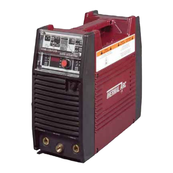
185 AC/DC
200 AC/DC
Service Manual
ARCMASTER
INVERTER ARC WELDERS
Revision No: AE.04
Operating Features:
GTAW
®
Art # A-07227
Issue Date: May 22, 2006
50
INVERTER
Hz
60
SMAW
Manual No.: 0-4884B
AC
CC
DC
Table of
Contents
Previous
Page
Next
Page
1
2
3
4
5
Advertisement
Table of Contents
Troubleshooting
BASIC TROUBLESHOOTING
39
ADVANCED TROUBLESHOOTING
51
Need help?
Do you have a question about the 185 AC and is the answer not in the manual?
Ask a question
Questions and answers
Related Manuals for Thermal Arc 185 AC
Welding System Thermal Arc ARCMASTER 200 TS Service Manual
Inverter arc welder (96 pages)
Welding System Thermal Arc ARCMASTER 185 AC/DC Operating Manual
Inverter arc welder (74 pages)
Welding System Thermal Arc 181i Fabricator Service Manual
3 in 1 multi-process welding system (106 pages)
Welding System Thermal Arc Fabricator 181i Operating Manual
3 in 1 multi-process welding systems (100 pages)
Welding System Thermal Arc FABRICATOR 181i Operating Manual
Multi process welding inverter (80 pages)
Welding System Thermal Arc 161 S Operating Manual
Inverter arc welder (56 pages)
Welding System Thermal Arc ARC MASTER 175 TE Operating Manual
Arc master inverter arc welder (52 pages)
Welding System Thermal Arc FABRICATOR 190 Operating Manual
Mig welding machine (64 pages)
Welding System Thermal Arc 190 Fabricator Service Manual
Mig welding machine (90 pages)
Welding System Thermal Arc 155 SE User Manual
(22 pages)
Welding System Thermal Arc 175 SE ARC MASTER Operating Manual
Inverter arc welder (44 pages)
Welding System Thermal Arc 160 TS ARCMASTER Service Manual
Inverter arc welder (114 pages)
Welding System Thermal Arc Fabricator 180 Service Manual
Thermal arc fabricator 140; fabricator 180 welding machine (84 pages)
Welding System Thermal Arc 186 AC Setup Manual
(16 pages)
Welding System Thermal Arc 186 DC Setup Manual
(16 pages)
Welding System Thermal Arc Raider 10,000 Pro K Owner's Manual
Thermal arc dc cc/cv welding generator, stick, mig, auxiliary power (33 pages)
This manual is also suitable for:
185 dc
200 ac
200 dc
Arcmaster 200
185 ac/dc arcmaster
200 ac/dc arcmaster
...
Show all
Arcmaster a-07227
Table of Contents
Save PDF
Print
Rename the bookmark
Delete bookmark?
Delete from my manuals?
Login
Sign In
OR
Sign in with Facebook
Sign in with Google
Upload manual
Upload from disk
Upload from URL


Need help?
Do you have a question about the 185 AC and is the answer not in the manual?
Questions and answers