
Related Manuals for Sandstrom S42SWLH13


Summary of Contents for Sandstrom S42SWLH13
- Page 1 Instruction Manual Soundbar with wireless sub-woofer S42SWLH13 S42SWLH13_IB_RC_130531_Michelle.indd 1 31/5/13 5:28 PM...
- Page 2 S42SWLH13_IB_RC_130531_Michelle.indd 2 31/5/13 5:28 PM...
-
Page 3: Table Of Contents
Contents Safety Warnings ........................4 Unpacking ..........................6 Product Overview .........................7 The Main Unit ..............................7 Rear View of Sub-woofer ...........................8 Remote Control ........................9 Remove the Plastic Strip from the Remote Control ............10 Battery Replacement for the Remote Control ..............10 Remote Control Operation Range ..................11 Wall Mounting ........................12 Connections ........................15 Using the HDMI Connection ......................... -
Page 4: Safety Warnings
Safety Warnings • Read all the instructions carefully before Ventilation using the unit and keep them for future • To prevent the risk of electric shock or reference. fire hazard due to overheating, ensure • Retain the manual. If you pass the unit that curtains and other materials do not onto a third party make sure to include this obstruct the ventilation vents. - Page 5 Interference Service • Do not place the unit on or near appliances • To reduce the risk of electric shock, do not which may cause electromagnetic remove screws. The unit does not contain interference. If you do, it may adversely any user-serviceable parts.
-
Page 6: Unpacking
Thank you for purchasing your new Sandstrøm Soundbar. We recommend that you spend some time reading this instruction manual in order that you fully understand all the operational features it offers. You will also find some hints and tips to help you resolve any issues. Read all the safety instructions carefully before use and keep this instruction manual for future reference. -
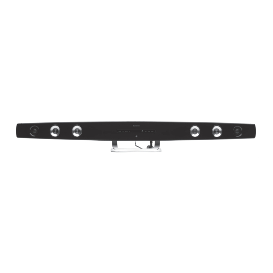
Page 7: Product Overview
Product Overview The Main Unit Front View STANDBY MP3 LINK COAXIAL OPTICAL HDMI1 HDMI2 1. Speakers 3. Status LED Indicators • Lights up red when the unit is in 2. Remote Control Sensor STANDBY mode. Receives signal from the remote • Lights up blue in Bluetooth mode. -
Page 8: Rear View Of Sub-Woofer
Rear View 1 2 3 MP3 LINK COAXIAL OPTICAL DC IN MP3 LINK HDMI IN 1 HDMI IN 2 HDMI OUT 6 7 8 1. AUX (L/R) Sockets 5. DC IN Socket 2. MP3 LINK Socket 6. HDMI IN 1 Socket 3. -
Page 9: Remote Control
Remote Control Button Switches the unit between ON and STANDBY modes. 2. AUX/MP3 Button AUX/ MP3 LINK Switches to AUX or MP3 mode. 3. VOL + Button MUTE S-BASS Increases the volume. – 4. EQ Button COAXIAL OPTICAL Switches between preset equalisers. HDMI 1 HDMI 2 5. -
Page 10: Remove The Plastic Strip From The Remote Control
Remove the Plastic Strip from the Remote Control Remove the plastic strip from the battery if the battery is being used for the first time. It is located at the bottom rear of the remote control. Battery Replacement for the Remote Control The remote control requires a CR2032, 3V Lithium battery (included). -
Page 11: Remote Control Operation Range
Handling the Battery • Improper or incorrect use of batteries may cause corrosion or battery leakage, which could cause fire, personal injury or damage to property. • Install the battery correctly in the battery compartment. Normally the battery’s positive polarity (+) will face up. -
Page 12: Wall Mounting
Wall Mounting Assembly is required. Installation must be carried out by qualified personnel only. Incorrect assembly can result in severe personal injury and property damage (if you intend to install this product yourself, you must check for installations such as electrical wiring and plumbing that may be buried inside the wall). The supplied wall bracket is only for use on vertical walls constructed from solid brick, solid concrete, solid wood, solid wooden battens, drywall, plaster wall and lath wall. - Page 13 Use an electronic stud finder to check the wall type before drilling and mounting. 3. Drill 2 parallel holes (Ø 3-8 mm each according to wall type) in the wall. The distance between the holes should be 110 mm. Solid wall ø8mm 50mm ø3mm...
- Page 14 5. Insert 1 screw into each dowel. Be sure to leave a 5 mm gap between the wall and the screw’s head. 5 mm Screw Dowel Wall (Side view) 6. Lift the unit with the attached wall bracket over the heads of the screws and slot into place.
-
Page 15: Connections
Connections Using the HDMI Connection Use an HDMI cable (not included) to connect an AV device’s HDMI OUT socket to the unit’s HDMI IN 1 or HDMI IN 2 socket. Use another HDMI cable (not included) to connect a visual device’s HDMI IN socket to the unit’s HDMI OUT socket. -
Page 16: Using The Mp3 Link Connection
Using the MP3 LINK Connection Use 3.5mm to 3.5mm stereo audio cable (not included) to connect a mobile device’s earphone socket to the unit’s MP3 LINK (3.5mm stereo audio input) socket. 3.5mm to 3.5mm stereo audio cable (not included) MP3 LINK COAXIAL OPTICAL DC IN... -
Page 17: Connecting To The Mains Supply
Connecting to the Mains Supply • The Soundbar and sub-woofer are designed to operate with the supplied mains adapter and mains cables. • Connecting the Soundbar to any other power source may damage the unit. Unwind the mains adapter and mains cable to their full length. Connect the mains adapter to the DC IN socket of the unit, then connect the mains cable to the mains adapter and into a mains socket. -
Page 18: General Operation
General Operation During STANDBY mode, the STANDBY indicator will light up red. Press STANDBY on • the main unit or on the remote control to turn the unit on. Press STANDBY to switch the unit back to STANDBY mode. • •... -
Page 19: Line In Operation
LINE IN Operation There are AUX, MP3 LINK, COAXIAL, OPTICAL and HDMI (input) sockets located at the rear of the unit. Analogue audio sound signals from other sources can be connected to the unit through these sockets. 1. Before connecting to the mains socket: • Use an optical cable (not included) to connect the audio device’s OPTICAL OUT socket to the unit’s OPTICAL (input) socket. -
Page 20: Nfc (Near Field Communication) Operation
2. Activate your Bluetooth device and select the search mode. 3. “S42SWLH13” will appear on your Bluetooth device. 4. Select “S42SWLH13” and enter “0000” for password if necessary. 5. On successful pairing, the unit will beep and the blue LED will light up solidly. -
Page 21: Hints And Tips
I cannot find • Ensure the Bluetooth function is activated on your “S42SWLH13” on my Bluetooth device. Bluetooth device. • Re-pair the unit with your Bluetooth device. -
Page 22: Specifications
Specifications Model S42SWLH13 Power Supply Input: 100-240V ~ 50/60Hz, 1.35A Output: 27.0V, 2.5A ECO Standby Power < 0.5W Soundbar Output Power 50W x 2 Power Consumption Frequency Response 200Hz - 20kHz Bluetooth Bluetooth 2.0 (A2DP) Signal to Noise Ratio > 70dB AUX Input 1V ±... - Page 23 For general information about this appliance and handy hints and tips, please visit www.knowhow.com/knowledgebank or call 0844 5611234. Visit Partmaster.co.uk today for the easiest way to buy electrical spares and accessories. With over 1 million spares and accessories available we can deliver direct to your door the very next day.
- Page 24 DSG Retail Ltd. (co. no. 504877) Maylands Avenue, Hemel Hempstead, Herts., HP2 7TG, UK IB-S42SWLH13-130531V3 S42SWLH13_IB_RC_130531_Michelle.indd 24 31/5/13 5:28 PM...
Need help?
Do you have a question about the S42SWLH13 and is the answer not in the manual?
Questions and answers