
Related Manuals for XMark Fitness XM-4424


Summary of Contents for XMark Fitness XM-4424
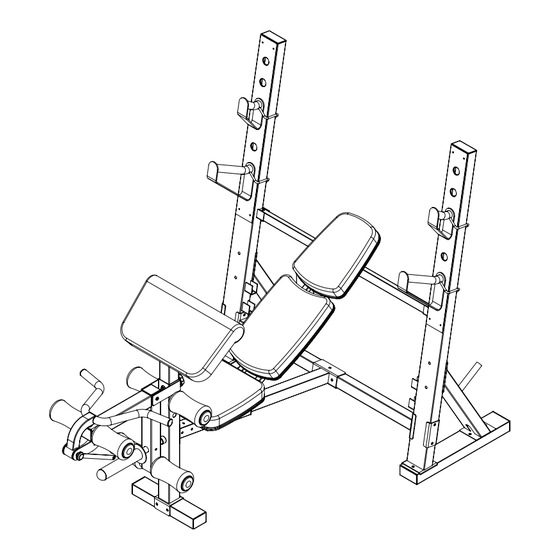
- Page 1 XM-4424 INTERNATIONAL OLYMPIC BENCH with LEG & PREACHER Owner’s Manual Read all precautions and instructions in this manual before using this equipment. 8/09...
-
Page 2: Table Of Contents
Table of Contents Before You Begin Important Safety Information Parts Identifier Assembly 6-15 Adjustments Attachments Parts List Exploded View Warranty Information... -
Page 3: Before You Begin
This manual will guide you through the assembly process. If at any time you are having trouble with the assembly or use of this product, then please contact us at our XMARK Fitness help line. We have trained service technicians on site to take care of you, our valued customer. -
Page 4: Important Safety Information
SAFETY PRECAUTIONS • This unit should only be used on a level surface and is intended for indoor use only. XMARK Fitness recommends an equipment mat be placed under the unit to protect the floor or carpet and for easier cleaning. -
Page 5: Parts Identifier
Parts Identifier Getting Started - The XMARK Fitness International Bench requires some assembly. Unpack the box in a clear area. Remove packing material. Do not dispose of packing material until assembly is complete and unit is working properly. Place the unit on a clean level surface for assembly. -
Page 6: Assembly
Assembly Note: Make sure the recessed areas around the holes on stabilizers are on the bottom. Step 1 Insert four M10X60mm carriage bolts (29) up through the bottom of the right stabilizer (2). Attach the right upright (4) to the right stabilizer (2) with indicated carriage bolts and locknuts (58). - Page 7 Assembly Step 2 Attach the cross bar (5) to the right upright (4) using two M10X120mm bolts (14), an upright plate (15), and two M10 lock nuts (58). Repeat to complete the assembly for the left upright (not shown). Figure 2 Step 3 Attach the right rear support (7) to the right stabilizer (2) using the indicated M10X60mm carriage bolts (29) and two M10 lock nuts (58).
- Page 8 Assembly Step 4 Attach the front leg (12) to the front stabilizer (11) with two M10X95mm bolts (64) and two M10 lock nuts (58). Figure 4 Step 5 Position the frame (8) so that the hexagonal holes are on the bottom. Attach the frame (8) to the crossbar (5) using three M10X70mm bolts (33), two M10 washers (43), and three M10 lock nuts (58).
- Page 9 Assembly Step 6 Pull the Pop Pin (45) out as far as it will go and slide the seat carriage (42) onto the Frame (8). Attach the front leg (12) to the frame (8) using two M8X60mm bolts (59), two M8X65mm bolts (46), six M8 washers (50), and four M8 lock nuts (49).
- Page 10 Assembly Step 8 Attach the tether on the seat adjustment pin (40) to the seat frame (10) using an M4X16mm screw (57). Attach the seat pad (21) to the seat frame (10) with four M6X20mm screws (41). Figure 8 Step 9 (25) Attach the Upper Back Pad (22) and Lower Back Pad...
- Page 11 Assembly Step 10 Apply a small amount of grease (included) to an M10X145mm bolt (53). Attach the seat frame (10) and the backrest frames (17) to the seat carriage (42) using the M10X145mm bolt (53), two M10 washers (43), and an M10 lock nut (58). Note: 1) The seat pad (21) has been removed from the drawing to clarify the installation to the seat carriage (42).
- Page 12 Assembly Step 12 Apply grease to the barrel of the M10X70mm bolt set (55). Next, attach the leg lever (18) to the front leg (12) and secure using the bolt set (55). Make sure the barrel of the bolt set (55) is inserted through both sides of the bracket on the front leg (12).
- Page 13 Assembly Step 14 Insert a weight rest (39) into the right upright (4) and secure by engaging the locking bar around the upright. Insert a safety spotter (27) into the right upright (4) and secure by engaging the locking bar around the upright.
- Page 14 Assembly Step 16 Attach the curl bar (31) to the leg lever (18) and secure with the curl bar pin (28). Next, attach the tether on the curl bar pin (28) to the leg lever (18) using a M4X16mm screw (57). Figure 16 Step 17 Tighten all hardware from the previous steps using the appropriate tools.
- Page 15 Assembly CONGRATULATIONS! You have completed assembly of your XMARK Fitness International Olympic Bench...
-
Page 16: Adjustments
Adjustments Seat Adjustments To move the seat (21), loosen the Pop pin (45) and pull it out as far as it will go. Slide the seat carriage (42) to the desired position and release the pop pin (45) back into the bench frame (8). -
Page 17: Attachments
Attachments Curl Bar Attachment Attach the curl bar (31) to the leg lever (18) and secure by inserting the curl bar pin (28). Note: You will need to remove the curl bar when using the leg extension. Olympic Plate Adapter To use olympic weights, secure the olympic adapter (47) to the weight tube (19) using M8X10mm set screw (60). - Page 18 Attachments Arm Curl Post Remove the 64mm square inner cap (69) from front leg (12). Insert the curl post (13) into the front leg (12) and align the holes. Secure the curl post (13) with the curl post knob (56). Note: Make sure that the knob is fully tightened.
-
Page 19: Parts List
Parts List XM-4424 Parts List Key NO. Part No. DESCRIPTION 204051402503 LEFT STABILIZER, XM - 4424 204051401503 RIGHT STABILIZER, XM - 4424 204051403503 LEFT UPRIGHT, XM - 4424 204051499503 RIGHT UPRIGHT, XM - 4424 204050518503 CROSS BAR, XM-442 204051405503 LEFT REAR SUPPORT, XM - 4424... -
Page 20: Exploded View
Exploded View... - Page 21 Exploded View...
-
Page 22: Warranty Information
Should any product submitted for warranty service be found ineligible, an estimate of repair cost will be furnished and the repair will be made if requested by you upon XMARK Fitness’... - Page 23 XMARK Fitness 7501 Trammel Drive Shreveport, LA 71108 Customer Service: 1-800-719-4605...
Need help?
Do you have a question about the XM-4424 and is the answer not in the manual?
Questions and answers