
Related Manuals for Avalue Technology EMX-A55E


Summary of Contents for Avalue Technology EMX-A55E
- Page 1 EMX-A55E AMD G-Series™ APU with A55E Controller Hub(FCH) Mini-ITX Motherboard User’s Manual Ed –29 June , 2011 Part No. E2047XA5500R...
- Page 2 Disclaimer Avalue Technology Inc. reserves the right to make changes, without notice, to any product, including circuits and/or software described or contained in this manual in order to improve design and/or performance. Avalue Technology assumes no responsibility or liability for the...
-
Page 3: Technical Support
User’s Manual otherwise specified. Applications that are described in this manual are for illustration purposes only. Avalue Technology Inc. makes no representation or warranty that such application will be suitable for the specified use without further testing or modification. Life Support Policy Avalue Technology‟s PRODUCTS ARE NOT FOR USE AS CRITICAL COMPONENTS IN... - Page 4 Avalue Technology Inc. 2F keduka-Bldg, 2-27-3 Taito, Room 805, Building 9,No.99 Tianzhou Rd., Taito-Ku, Tokyo 110-0016 Japan Caohejing Development Area, Tel: +81-3-5807-2321 Xuhui District, Shanghai Fax: +81-3-5807-2322 Tel: +86-21-5169-3609 Fax:+86-21-5445-3266 Information: sales.japan@avalue.com.tw Information: sales.china@avalue.com.cn Service: service@avalue.com.tw Service: service@avalue.com.tw 4 EMX-A55E User‟s Manual...
-
Page 5: Table Of Contents
Serial Port Connector (COM3, COM4) ................... 35 2.4.10 System Panel & Speaker (JFP1 + JFP2)................... 35 2.4.11 Power LED & Keylock (JFP3) ....................36 2.4.12 Inverter PWR (JBL1) ........................36 2.4.13 SPI connector (CN4) ........................37 EMX-A55E User‟s Manual 5... - Page 6 Memory Configuration ........................56 3.2.3.2 North Bridge LVDS Config Select ...................... 57 3.2.3.3 South Bridge ............................58 3.2.3.3.1 SB SATA Configuration ......................... 58 3.2.3.3.2 SB USB Configuration ........................59 3.2.4 Boot ..............................60 3.2.5 Save & Exit ............................. 61 6 EMX-A55E User‟s Manual...
-
Page 7: Getting Started
Before you begin installing your single board, please make sure that the following materials have been shipped: 1 x EMX-A55E Mini ITX Main board 1 x CD-ROM contains the followings: - User‟s manual (this manual in PDF file) -... -
Page 8: Document Amendment History
EMX-A55E 1.3 Document Amendment History Revision Date Comment June 2011 Initial Release 8 EMX-A55E User‟s Manual... -
Page 9: Manual Objectives
We strongly recommend that you study this manual carefully before attempting to interface with EMX-A55E series or change the standard configurations. Whilst all the necessary information is available in this manual we would recommend that unless you are confident, you contact your supplier for guidance. -
Page 10: System Specifications
3D feature DirectX 11, OpenGL 4.0, dedicated hardware (UVD 3.0) LVDS 1, 18bpp (Single link LVDS up to 1400 x 1050) T56N (18W) supports up to 2560 x 1600 T40N (9W) supports up to 1920 x 1200 10 EMX-A55E User‟s Manual... - Page 11 FAN Speed Control by Thermal Sensor Temperature Voltage 3.3V, +5V, 5Vsb, +12V, -12V Buzzer Onboard buzzer Watchdog Timer Programmable 1~255 sec/min Onboard TPM1.1/1.2 By Infineon SLB9635 (Optional) BIOS BIOS Core AMI EFI BIOS Flash BIOS Flash 16Mb SPI EMX-A55E User‟s Manual 11...
- Page 12 Shared Memory up to 2GB Power Play 380, 200MHz, configure Power to 2.7~5.7W SATA Support SATA III(6Gbps) Internal Connector Debug Port HDT header Display LVDS 1, (optional) Inverter LVDS INV 3.3 V Audio Front Panel Amplifier SPDI/F Serial 12 EMX-A55E User‟s Manual...
- Page 13 1 jack connector Power Connector Power Type AT/ATX Power Requirement +3.3V, +5V, +12V, -12V, 5Vsb LED Indicator HDD Status 4; access, flash yellow Power on rear IO 1; Blue Expansion Slot Mini-PCI Express PCIex 4 EMX-A55E User‟s Manual 13...
- Page 14 SATA cable Kit 1 data and 1 power Serial Port I/O Shield Driver CD Startup Manual None FP_Power button, power LED, HDD LED kit None OS Support List Windows XP SP3, Windows 7 Pro, Linux Fedora 14 14 EMX-A55E User‟s Manual...
-
Page 15: Architecture Overview - Block Diagram
User’s Manual 1.6 Architecture Overview – Block Diagram The following block diagram shows the architecture and main components of EMX-A55E. EMX-A55E User‟s Manual 15... -
Page 16: Hardware Configuration
EMX-A55E 2. Hardware Configuration 16 EMX-A55E User‟s Manual... -
Page 17: Product Overview
Place four (4) screws into the holes indicated by circles to secure the motherboard to the chassis. Do not over tighten the screws! Doing so can damage the motherboard. Place this side towards the rear of the chassis EMX-A55E User‟s Manual 17... -
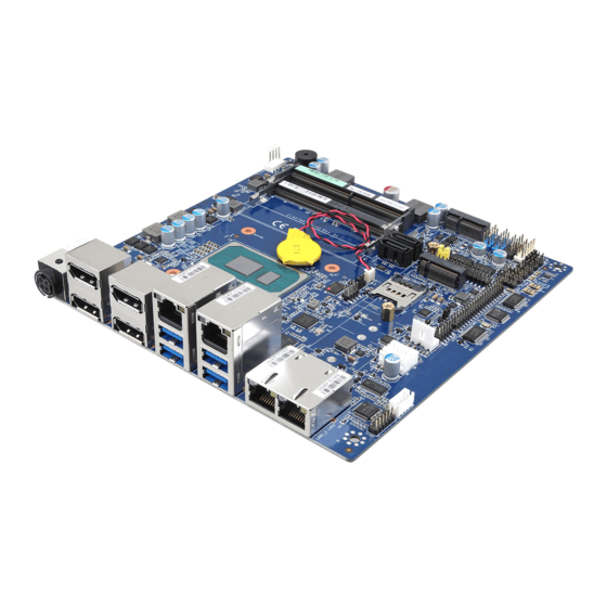
Page 18: Product Layout
EMX-A55E 2.2 Product Layout 18 EMX-A55E User‟s Manual... -
Page 19: Layout Content List
VGA_DVI VGA Connector D-sub 15-pin, female USB3,4,5,6 USB Connector x 4 2 x 5 Header, pitch 2.54mm LAN1,2 RJ-45 Ethernet Connector x 2 AUDIO Line-in Port, Line-out Port, 7.1 Channel Audio I/O (3 jacks) Microphone Port, EMX-A55E User‟s Manual 19... -
Page 20: Installation Procedure
Note: Make sure the heat sink and the CPU top surface are in total contact to avoid CPU overheating problem that would cause the system to hang or unstable 20 EMX-A55E User‟s Manual... -
Page 21: Central Processing Unit (Cpu)
These are not jumpers! DO NOT place jumper caps on the fan connectors. After installation, make sure to plug-in the ATX power cable to the motherboard. EMX-A55E User‟s Manual 21... -
Page 22: System Memory
This motherboard does not support memory modules made up of 128 Mb chips or double-sided x16 memory modules. Make sure that the memory frequency matches the CPU FSB (Front Side Bus). Refer to the Memory frequency/CPU FSB synchronization table. 22 EMX-A55E User‟s Manual... -
Page 23: Installing A Ddr3 Dimm
A DDR3 DIMM is keyed with a notch so that it fits in only one direction. DO NOT force a DIMM into a socket to avoid damaging the DIMM. The DDR3 DIMM sockets do not support DDR DIMMs. DO NOT install DDR DIMMs to the DDR3 DIMM socket. EMX-A55E User‟s Manual 23... -
Page 24: Removing A Ddr3 Dimm
Press the two ejector tabs on the slot outward simultaneously, and then pull out the DIMM module. Notch Key Mounting Notch Support the DIMM lightly with your fingers when pressing the ejector tabs. The DIMM might get damaged when it flips out with extra force. 24 EMX-A55E User‟s Manual... -
Page 25: Expansion Slots
Turn on the system and change the necessary BIOS settings if any. Assign an IRQ to the card if needed. Refer to the tables on the next page. Install the software drivers for the expansion card. EMX-A55E User‟s Manual 25... -
Page 26: Standard Interrupt Assignments
IRQ holder for PCI streeing* IRQ holder for PCI streeing* IRQ holder for PCI streeing* PS/2 Compatible Mouse Port* Numeric Data Processor Primary IDE Channel Secondary IDE Channel * There IRQs are usually available for ISA or PCI device. 26 EMX-A55E User‟s Manual... -
Page 27: Setting Jumpers & Connectors
In addition, the board has a number of jumpers that allow you to configure your system to suit your application. If you have any doubts about the best hardware configuration for your application, contact your local distributor or sales representative before you make any changes. EMX-A55E User‟s Manual 27... -
Page 28: Clear Cmos (Cmos1)
Hold down the <Del> key during the boot process and enter BIOS setup to re-enter data. Except when clearing the CMOS, never remove the cap on CLRTC jumper default position. Removing the cap will cause system boot failure! Normal (Default) Clear CMOS 28 EMX-A55E User‟s Manual... -
Page 29: Com3 Ri/+5V/+12V Selection (Jsetcom3)
User’s Manual 2.4.2 COM3 RI/+5V/+12V Selection (JSETCOM3) +12V Ring +5V (Default) 2.4.3 COM4 RI/+5V/+12V Selection (JSETCOM4) +12V Ring +5V (Default) EMX-A55E User‟s Manual 29... -
Page 30: Rear Panel Connectors
This port connects a tape, CD, DVD player, or other audio sources. AUDIO Line-Out port (Lime) This port connects a headphone or a speaker. In 4-channel, 6-channel, and 8-channel configuration, the function of this port becomes Front Speaker Out. 30 EMX-A55E User‟s Manual... - Page 31 (USB) ports are available for connecting USB 2.0 devices. HDMI This 15-pin port is for a VGA monitor or other VGA_DVI VGA port VGA-compatible devices. KBMS PS/2 KB connector This port is for a PS/2 keyboard EMX-A55E User‟s Manual 31...
-
Page 32: Front Panel Audio Connector (Aafp)
I/O module cable to this connector. For motherboards with the optional HD Audio feature, we recommend that you connect a high-definition front panel audio module to this connector to avail of the motherboard‟s high‑definition audio capability. 32 EMX-A55E User‟s Manual... -
Page 33: Atx Power Connector (Atxpwr)
300W for a fully configured system. The system can become unstable and might experience difficulty powering up if the power supply is inadequate. You must install a PSU with a higher power rating if you intend to install additional devices. EMX-A55E User‟s Manual 33... -
Page 34: At/Atx Mode Select (Pson1)
EMX-A55E 2.4.7 AT/ATX Mode Select (PSON1) ATX MODE (Default) AT MODE 2.4.8 LCD POWER (VDDSAFE) (JBL3) 3.3V (Default) 34 EMX-A55E User‟s Manual... -
Page 35: Serial Port Connector (Com3, Com4)
User’s Manual 2.4.9 Serial Port Connector (COM3, COM4) COM3 COM4 2.4.10 System Panel & Speaker (JFP1 + JFP2) PIN7-10 Internal SPK PIN3-6 POWER BT PIN1-10 External SPK PIN9-12 SYS_RESET EMX-A55E User‟s Manual 35... -
Page 36: Power Led & Keylock (Jfp3)
EMX-A55E 2.4.11 Power LED & Keylock (JFP3) 2.4.12 Inverter PWR (JBL1) 36 EMX-A55E User‟s Manual... -
Page 37: Spi Connector (Cn4)
User’s Manual 2.4.13 SPI connector (CN4) 2.4.14 SPDIF OUT (SPDIF_OUT1) EMX-A55E User‟s Manual 37... -
Page 38: 18-Bit Lvds Connector (Lvds1)
EMX-A55E 2.4.15 18-bit LVDS Connector (LVDS1) 2.4.16 AMP_R+R-/AMP_L+L- (CN10) 38 EMX-A55E User‟s Manual... -
Page 39: Serial Ata Connector (Sata1, Sata2)
Install the Windows® 2000 Service Pack 4 or the Windows® XP Service Pack1 before using Serial ATA. When using the connectors in Standard IDE mode, connect the primary (boot) hard disk drive to the SATA1 connector. EMX-A55E User‟s Manual 39... -
Page 40: Usb 2.0 Connector (Usb56)
These USB connectors comply with USB 2.0 specification that supports up to 480 Mbps connection speed. Never connect a 1394 cable to the USB connectors. Doing so will damage the motherboard! The USB module is purchased separately. 40 EMX-A55E User‟s Manual... -
Page 41: Bios Setup
User’s Manual 3. BIOS Setup EMX-A55E User‟s Manual 41... -
Page 42: Introduction
The BIOS setup screens shown in this section are for reference purposes only, and may not exactly match what you see on your screen. Visit the system builder‟s website to download the latest BIOS file for this motherboard 42 EMX-A55E User‟s Manual... -
Page 43: Legend Box
While moving around through the Setup program, note that explanations appear in the Item Specific Help window located to the right of each menu. This window displays the help text for the currently highlighted field. EMX-A55E User‟s Manual 43... -
Page 44: Bios Setup
This section allows you to record some basic hardware configurations in your computer and set the system clock. Date [Day, xx/ xx/ xxxx] The date format is <week>, <month>, <day>, <year>. Time [xx : xx : xx] The time format is <hour><minute><second>, based on the 24-hour clock. 44 EMX-A55E User‟s Manual... -
Page 45: Advanced
Item Options Description Enabled Enable or Disable Boot Option for Legacy Launch PXE OpROM Disabled Network Devices Enabled Enable or Disable Boot Option for Legacy Launch Storage OpROM Disabled Mass Storage Devices with Option ROM EMX-A55E User‟s Manual 45... -
Page 46: Acpi Setting
S3 Video Repost Enables or Disables S3 Video Repost Disabled Enabled PS2 Keyboard Wake up Enables or Disables PS2 Keyboard Wake up Disabled Enabled PS2 Mouse Wake up Enables or Disables PS2 Mouse Wake up Disabled 46 EMX-A55E User‟s Manual... -
Page 47: Cpu Configuration
Adjust startup P-state level PPC Adjustment PState 0/1/2/3/4/5/6/7 Adjust _PPC object Enabled Enable or Disable No-Execute page NX Mode Disabled protection Function Enabled SVM Mode Enable or Disable CPU Virtualization Disabled Enabled C6 Mode Enable or Disable C6 Disabled EMX-A55E User‟s Manual 47... -
Page 48: Node 0 Information
EMX-A55E 3.2.2.2.1 Node 0 Information 3.2.2.3 IDE Configuration 48 EMX-A55E User‟s Manual... -
Page 49: Usb Configuration
Maximum time the device will take before it properly reports itself to the host Controller. Auto “Auto” uses default value: for a Root port it is Device power-up delay Manual 100ms, for a Hub port the delay is taken from Hub. EMX-A55E User‟s Manual 49... -
Page 50: Second Super Io Configuration
Serial port function Mode IR Mode, Pulse 1,6us, Full Duplex Device Mode IR Mode, Pulse 1,6us, Half Duplex Change the serial Port mode IR Mode, Pulse 3/16 Bit Time, Full Duplex IR Mode, Pulse 3/16 Bit Time, half Duplex 50 EMX-A55E User‟s Manual... -
Page 51: Serial Port 4 Configuration
3.2.2.6.1 Smart Fan Mode Configuration Item Options Description Manual Mode SYS Smart Fan Mode SYS Smart Fan Mode selection Thermal Cruise Mode Manual Mode CPU Smart Fan 0 Mode CPU Smart Fan 0 Mode selection Thermal Cruise Mode EMX-A55E User‟s Manual 51... -
Page 52: Super Io Configuration
Set AC Power Loss function Last State Minute Watchdog Mode Set watchdog Timer Second 0 – 255 Input value (Range: 0 – 255) Watchdog Timer Enabled Case Open warning Enabled or Disable Case Open warning Disabled 52 EMX-A55E User‟s Manual... -
Page 53: Serial Port 0 Configuration
IO=2E8h;IRQ=3,4,5,6,7,10,11,12; 3.2.2.7.1 Serial Port 1 Configuration Item Options Description Enabled Serial Port Enables or Disabled Serial Port (COM) Disabled Auto IO=2F8h; IRQ=3 IO=3F8h;IRQ=3,4,5,6,7,10,11,12; Select an optimal setting for Super IO Change settings IO=2F8h;IRQ=3,4,5,6,7,10,11,12; device. IO=3E8h;IRQ=3,4,5,6,7,10,11,12; IO=2E8h;IRQ=3,4,5,6,7,10,11,12; EMX-A55E User‟s Manual 53... -
Page 54: Chipset
EMX-A55E 3.2.3 Chipset This category displays base memory, extended memory, and total memory detected during POST (Power On Self Test). 3.2.3.1 North Bridge 54 EMX-A55E User‟s Manual... -
Page 55: Node 0 Information
Options Description Disabled 32MB 64MB 128MB IOMMU is supported on LINUX based systems IOMMU Mode 256MB to convert 32bit I/O to 64bit MMIO. 512MB Disabled Memory Clear Memory Clear functionality control Enabled 3.2.3.1.1 Node 0 Information EMX-A55E User‟s Manual 55... -
Page 56: Memory Configuration
EMX-A55E 3.2.3.1.2 Memory Configuration Item Options Description Force Integrated Graphics Enable Integrated Graphics controller Disabled 32MB 64MB 128MB UMA Frame buffer Size 256MB Set UMA FB size 512MB 56 EMX-A55E User‟s Manual... -
Page 57: North Bridge Lvds Config Select
1280x720 1280x800 LVDS Panel Config Select 1280x1024 Select LVDS panel configuration 1366x768 1440x900 1600x900 1920x1024 0 – 255 Input Brightness Value (Range: 0 – 255) Brightness Control Value Enabled EDID Panel Option EDID Panel Option Disabled EMX-A55E User‟s Manual 57... -
Page 58: South Bridge
EMX-A55E 3.2.3.3 South Bridge 3.2.3.3.1 SB SATA Configuration Item Options Description Native IDE Native IDE/n RAID/n AHCI/n Legacy IDE /n Onchip SATA Type RAID IDEAHCI /n HyperFlash. AHCI 58 EMX-A55E User‟s Manual... -
Page 59: Sb Usb Configuration
Enable or Disable USB Port 6 Disabled Enabled USB Port 7 USB Port 7 Enable or Disable Disabled USB Device wakeup From S3 Enabled Enable or Disable USB Device Wake up from Disabled S3 or S4 or S4 EMX-A55E User‟s Manual 59... -
Page 60: Boot
GA20; this option is useful when any RT code is executed above 1MB Force BIOS Option ROM Messages Set display mode for Option ROM Keep current Enabled Interrupt 19 Capture Enabled” allows Option ROMs to trap Int 19 Disabled 60 EMX-A55E User‟s Manual... -
Page 61: Save & Exit
CMOS memory of the chipset. The processor will check this every time you turn your system on and compare this to what it finds as it checks the system. This record is required for the system to operate. EMX-A55E User‟s Manual 61...
Need help?
Do you have a question about the EMX-A55E and is the answer not in the manual?
Questions and answers