
Subscribe to Our Youtube Channel
Related Manuals for Avalue Technology EMX-H110TC


Summary of Contents for Avalue Technology EMX-H110TC
- Page 1 EMX-H110TC Intel® 6th Generation Core™ LGA1151 Socket Processors with Intel® H110 Mini ITX Motherboard User’s Manual Ed – 08 December 2017 Part No. E2047EMTC01R...
- Page 2 Disclaimer Avalue Technology Inc. reserves the right to make changes, without notice, to any product, including circuits and/or software described or contained in this manual in order to improve design and/or performance. Avalue Technology assumes no responsibility or liability for the...
-
Page 3: Technical Support
Applications that are described in this manual are for illustration purposes only. Avalue Technology Inc. makes no representation or warranty that such application will be suitable for the specified use without further testing or modification. -
Page 4: Product Warranty
Write the RMA number visibly on the outside of the package and ship it prepaid to your dealer. Warning: Battery Notice Important! To prolong battery life, please avoid adhering the battery to possible source of heat. 重要! 為了延長電池壽命,請避免電池附著在有可能出現高溫的地方 バッテリ寿命を延長するために、高温の付近にバッテリーを付着することを避けてくださ い。 4 EMX-H110TC User’s Manual... -
Page 5: Table Of Contents
Inverter control connector (IVCN1) .................... 29 2.3.20 LVDS connector (LVDS1) ......................30 2.3.21 LVDS backlight brightness adjustment (BKCL1) ............... 30 2.3.22 VGA connector (JVGA1) ......................31 2.3.23 Battery connector (BAT1) ......................31 3.BIOS Setup ........................32 Introduction ......................33 EMX-H110TC User’s Manual... - Page 6 4. Drivers Installation....................... 55 Install Chipset Driver ....................56 Install VGA Driver ....................57 Install ME Driver ...................... 59 Install Audio Driver (For Realtek ALC662 HD Audio) ..........60 Install LAN Driver ....................61 Install RST Driver ....................62 6 EMX-H110TC User’s Manual...
- Page 7 User’s Manual 5. Mechanical Drawing ....................64 EMX-H110TC User’s Manual...
-
Page 8: Getting Started
1.2 Packing List Before you begin installing your single board, please make sure that the following materials have been shipped: 1 x EMX-H110TC motherboard 1 x SATA Cable 1 x SATA Power Cable ... -
Page 9: Document Amendment History
User’s Manual 1.3 Document Amendment History Revision Date Comment October 2017 Avalue Initial Release December 2017 Avalue Increase Battery Notice EMX-H110TC User’s Manual... -
Page 10: Manual Objectives
We strongly recommend that you study this manual carefully before attempting to set up EMX-H110TC or change the standard configurations. Whilst all the necessary information is available in this manual we would recommend that unless you are confident, you contact your supplier for guidance. -
Page 11: System Specifications
Interface Internal I/O Connectors 1 x 1 x 4 pin, pitch 2.54mm CPU fan connector with smart fan function supported 1 x 1 x 4 pin, pitch 2.54mm System fan connector with smart fan function supported EMX-H110TC User’s Manual 11... - Page 12 1 x 1 x 4 pin, pitch 2.54mm CPU fan connector with smart fan function supported 1 x 1 x 4 pin, pitch 2.54mm System fan connector with smart fan function supported 1 x 1 x 12 pin, pitch 2.00mm connector for VGA 12 EMX-H110TC User’s Manual...
- Page 13 Windows 7 / Windows 10/ Linux with Intel document) Note: 1. Specifications are subject to change without notice. 2. LAN LED Behavior 1000M/1G Green 100 M LAN LED Green Data transmit Orange (Flashes) AT/ATX mode AT/ATX LCD Interface LVDSl EMX-H110TC User’s Manual 13...
- Page 14 Due to the different firmware version of chip CH7511, the brightness function of motherboards will have different behaviors. Motherboard: EMX-H110TC couldn’t use the hardware method (button) to keep the brightness value. After the motherboard wakes up from S3/S4/S5 modes, the brightness value of motherboard will change back to the default value (brightest).
-
Page 15: Architecture Overview-Block Diagram
User’s Manual 1.6 Architecture Overview—Block Diagram The following block diagram shows the architecture and main components of EMX-H110TC. EMX-H110TC User’s Manual 15... -
Page 16: Hardware Configuration
EMX-H110TC User’s Manual 2. Hardware Configuration 16 EMX-H110TC User’s Manual... -
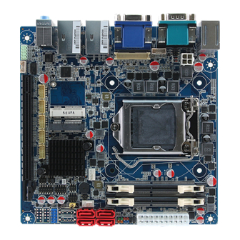
Page 17: Product Overview
User’s Manual 2.1 Product Overview EMX-H110TC User’s Manual 17... -
Page 18: Jumper And Connector List
3 x 1 header, pitch 2.00mm JPWR_LVDS1 LVDS power selection 3 x 2 header, pitch 2.54mm Connectors Label Function Note 4 x 1 wafer, pitch 2.54mm CFAN1 CPU fan connector 4 x 1 wafer, pitch 2.54mm SFAN1 System fan connector 18 EMX-H110TC User’s Manual... - Page 19 BAT1 Battery connector 1 x 4 wafer, pitch 2.00mm BKCL1 LVDS backlight brightness adjustment 6 x 1 wafer, pitch 2.00mm IVCN1 Inverter control connector VGA1 VGA connector 12 x 1 wafer, pitch 2.00mm JVGA1 VGA connector EMX-H110TC User’s Manual 19...
-
Page 20: Setting Jumpers & Connectors
EMX-H110TC User’s Manual 2.3 Setting Jumpers & Connectors 2.3.1 Serial port 1/2 pin9 signal select (JC11/21) JC21 +12V JC11 * Default 2.3.2 Serial port 2 RS-232/422/485 mode selector (JC22) RS-232* RS-485 RS-422 * Default 20 EMX-H110TC User’s Manual... -
Page 21: Panel Type Control Selector (J1/2/3/4)
VCC3 2-3 pin J2/J4 Default: VCC3(1-2 pin) Resolution 1024x768 24/1 800x600 18/1 1024x768 18/1 1366x768 18/1 1024x600 18/1 1280x800 18/1 1920x1200 24/2 1920x1080 18/2 1280x1024 24/2 1440x900 18/2 1600x1200 24/2 1366x768 24/1 1920x1080 24/2 1680x1050 24/2 EMX-H110TC User’s Manual 21... -
Page 22: At/Atx Input Power Select (At)
EMX-H110TC User’s Manual 2.3.4 AT/ATX Input power select (AT) * Default 2.3.5 Clear CMOS (CLR_CMOS1) Normal* Clear CMOS * Default 22 EMX-H110TC User’s Manual... -
Page 23: Flash Bios Me Connector (Jme)
User’s Manual 2.3.6 Flash BIOS ME connector (JME) Normal* Override * Default 2.3.7 LVDS power selection (JPWR_LVDS1) 3.3V* +12V * Default EMX-H110TC User’s Manual 23... -
Page 24: Speaker Connector (Jspk1)
EMX-H110TC User’s Manual 2.3.8 Speaker connector (JSPK1) Signal INTSPR+ INTSPR- INTSPL- INTSPL+ 2.3.9 Serial port 1/2 connector (JCOM1/2) JCOM2 JCOM1 Signal PIN PIN Signal 24 EMX-H110TC User’s Manual... -
Page 25: Front Panel Connector (F_Panel1)
User’s Manual 2.3.10 Front Panel connector (F_PANEL1) Signal PIN PIN Signal PBTNJ_SIO SYS_RST_N SATA_LED_N POWER_LED+ HDLED+ 2.3.11 USB 3.0 connector (F_USB1) Signal Signal POWER_FUSB POWER_FUSB USB3_RXN3 USB3_RXN4 USB3_RXP3 USB3_RXP4 USB3_TXN3 USB3_TXN4 USB3_TXP3 USB3_TXP4 USB_D3- USB_D4- USB_D3+ USB_D4+ EMX-H110TC User’s Manual 25... -
Page 26: Usb 2.0 Connector (F_Usb2)
EMX-H110TC User’s Manual 2.3.12 USB 2.0 connector (F_USB2) Signal PIN PIN Signal POWER_JUSB2 POWER_JUSB2 USBH_TN1 USBH_TN2 USBH_TP1 USBH_TP2 2.3.13 Front Audio connector (F_AUDIO1) Signal PIN PIN Signal MIC2_L MIC2_R LINE2_R SENSE_B LINE2_L SENSE_B 26 EMX-H110TC User’s Manual... -
Page 27: System Fan Connector (Sfan1)
User’s Manual 2.3.14 System fan connector (SFAN1) Signal +12V FAN_TAC2 FAN_CTL2 2.3.15 CPU fan connector (CFAN1) Signal +12V FAN_TAC1 FAN_CTL1 EMX-H110TC User’s Manual 27... -
Page 28: Sata Power Connector 1(Jsata_Pwr1)
EMX-H110TC User’s Manual 2.3.16 SATA power connector 1(JSATA_PWR1) Signal VCC12 2.3.17 SATA power connector 2 (JSATA_PWR2) Signal VCC12 28 EMX-H110TC User’s Manual... -
Page 29: Power Connector (Dc12V1)
User’s Manual 2.3.18 Power connector (DC12V1) Signal Signal AC_IN AC_IN 2.3.19 Inverter control connector (IVCN1) Signal +12V +12V CHENBKLT BKLTCTL EMX-H110TC User’s Manual 29... -
Page 30: Lvds Connector (Lvds1)
12 CHLVDS_DATA2P CHLVDS_CLK1N CHLVDS_CLK1P CHLVDS_DATA3N 17 18 CHLVDS_DATA3P CHLVDS_DATA4N 19 20 CHLVDS_DATA4P CHLVDS_DATA5N 21 22 CHLVDS_DATA5P CHLVDS_DATA6N 23 24 CHLVDS_DATA6P CHLVDS_CLK2N CHLVDS_CLK2P CHLVDS_DATA7N 29 30 CHLVDS_DATA7P 2.3.21 LVDS backlight brightness adjustment (BKCL1) Signal CH_BLUP CH_BLDN CH_PWRDN 30 EMX-H110TC User’s Manual... -
Page 31: Vga Connector (Jvga1)
User’s Manual 2.3.22 VGA connector (JVGA1) Signal VSYNC_C HSYNC_C C_VGA_RED C_VGA_GREEN C_VGA_BLUE VGA_5VDDA VGA_5VDDCLK 2.3.23 Battery connector (BAT1) Signal +3.3VSB EMX-H110TC User’s Manual 31... -
Page 32: Bios Setup
EMX-H110TC User’s Manual 3.BIOS Setup 32 EMX-H110TC User’s Manual... -
Page 33: Introduction
If the message disappears before you respond and you still wish to enter Setup, restart the system to try again by turning it OFF then ON or pressing the "RESET" button on the system case. You may also restart by simultaneously pressing <Ctrl>, <Alt>, and <Delete> keys. EMX-H110TC User’s Manual 33... -
Page 34: Using Setup
Note: Some of the navigation keys differ from one screen to another. To Display a Sub Menu Use the arrow keys to move the cursor to the sub menu you want. Then press <Enter>. A “” pointer marks all sub menus. 34 EMX-H110TC User’s Manual... -
Page 35: Getting Help
BIOS Vendor and your systems manufacturer to provide the absolute maximum performance and reliability. Even a seemingly small change to the chipset setup has the potential for causing you to use the override. EMX-H110TC User’s Manual 35... -
Page 36: Bios Setup
<Enter> to accept and enter the sub-menu. 3.6.1 Main Menu This section allows you to record some basic hardware configurations in your computer and set the system clock. 36 EMX-H110TC User’s Manual... -
Page 37: System Language
Visit the Avalue website (www.avalue.com.tw) to download the latest product and BIOS information. 3.6.2 Advanced Menu This section allows you to configure your CPU and other system devices for basic operation through the following sub-menus. EMX-H110TC User’s Manual 37... -
Page 38: Apci Settings
ACPI Sleep State system will enter when the SUSPEDN S3 (Suspend to RAM)[Default] button is pressed. Disabled[Default] 30 sec 40 sec 50 sec Watch dog Timer Select WatchDog. 1 min 2 min 10 min 30 min 38 EMX-H110TC User’s Manual... -
Page 39: It8784 Super Io Configuration
Please refer to 3.6.2.2.1~ 3.6.2.2.2 for more information. Item Description Serial Port 1 Configuration Set Parameters of Serial Port 1 (COMA). Serial Port 2 Configuration Set Parameters of Serial Port 2 (COMB). 3.6.2.2.1 Serial Port 1 Configuration EMX-H110TC User’s Manual 39... -
Page 40: Serial Port 2 Configuration
EMX-H110TC User’s Manual Item Option Description Disabled Serial Port Enable or Disable Serial Port (COM). Enabled[Default] 3.6.2.2.2 Serial Port 2 Configuration Item Option Description Disabled Serial Port Enable or Disable Serial Port (COM). Enabled[Default] 3.6.2.3 Hardware Monitor 40 EMX-H110TC User’s Manual... -
Page 41: Cpu Configuration
Item Option Description Full on Mode Smart Fan 1 Mode Automatic Mode[Default] Smart Fan 1 Mode Select. Manual Mode 3.6.2.4 CPU Configuration Use the CPU configuration menu to view detailed CPU specification and configure the CPU. EMX-H110TC User’s Manual 41... -
Page 42: Sata Configuration
Determines how SATA controller(s) operate. Enabled[Default] Port 1/2/3 Enable or Disable SATA Port. Disabled Hard Disk Drive[Default] Identify the SATA port is connected to Solid SATA Device Type Solid State Drive State Drive or Hard Disk Drive. 42 EMX-H110TC User’s Manual... -
Page 43: Network Stack Configuration
User’s Manual 3.6.2.6 Network Stack Configuration Item Options Description Disabled[Default] Network Stack Enable/Disable UEFI Network Stack. Enabled 3.6.2.7 CSM Configuration Item Options Description Enabled CSM Support Enable/Disable CSM Support. Disabled[Default] EMX-H110TC User’s Manual 43... -
Page 44: Usb Configuration
Root port it is 100ms, for a Hub port the delay is taken form Hub descriptor. Mass storage device emulation type. ‘AUTO’ Auto[Default] Mass Storage Devices Floppy enumerates devices according to their media 44 EMX-H110TC User’s Manual... -
Page 45: Chipset
User’s Manual format. Optical drives are emulated as ‘CDROM’, Forced FDD Hard Disk drives with no media will be emulated according CD-ROM to a drive type. 3.6.3 Chipset 3.6.3.1 System Agent (SA) Configuration EMX-H110TC User’s Manual 45... -
Page 46: Memory Configuration
Description Maximum Memory Auto[Default]/1067/1333/1600/1867 Maximum Memory Frequency Selections Frequency /2133/2400/2667/2933/3200 in Mhz. Maximum Value of TOLUD. Dynamic Dynamic/1GB/1.25GB/1.5GB/1.75GB assignment would adjust TOLUD Max TOLUD /2GB/2.25GB/2.5GB/2.75GB automatically based on largest MMIO /3GB/3.25GB/3.5GB[Default] length of installed graphic controller. 46 EMX-H110TC User’s Manual... -
Page 47: Pch-Io Configuration
Specify what state to go to when power is Restore AC Power Loss Power On re-applied after a power failure (G3 state). Last State Disabled[Default] Wake On LAN From S5 Enable Or Disable Wake On LAN From S5. Enabled 3.6.3.2.1 PCI Express Configuration EMX-H110TC User’s Manual 47... - Page 48 EMX-H110TC User’s Manual 3.6.3.2.1.1 PCI Express Root Port 5 Item Option Description Enabled[Default], Realtek LAN 1 Contrller Control the PCI Express Root Port. Disabled 3.6.3.2.1.2 PCI Express Root Port 6 48 EMX-H110TC User’s Manual...
- Page 49 L0s State AUTO – BIOS auto ASPM Support configure DISABLE – Disables ASPM. L0sL1 Auto Disabled L1.1 L1 Substates PCI Express L1 Substates settings. L1.2 L1.1 & L1.2[Default], Auto[Default] PCIe Speed Gen1 Select PCI Express port speed. Gen2 EMX-H110TC User’s Manual 49...
- Page 50 L0s State AUTO – BIOS auto ASPM Support configure DISABLE – Disables ASPM. L0sL1 Auto Disabled L1.1 L1 Substates PCI Express L1 Substates settings. L1.2 L1.1 & L1.2[Default], Auto[Default] PCIe Speed Gen1 Select PCI Express port speed. Gen2 50 EMX-H110TC User’s Manual...
-
Page 51: Hd Audio Configuration
Option Description Control Detection of the HD-Audio device. Disabled= HDA Disabled will be unconditionally disabled Enabled= HDA will be HD Audio Enabled unconditionally enabled Auto= HDA will be enabled if Auto[Default] present, disabled otherwise. 3.6.4 Security EMX-H110TC User’s Manual 51... -
Page 52: Boot
Setup Prompt Timeout 1~ 65535 activation key. 65535(0xFFFF) means indefinite waiting. On[Default] Bootup NumLock State Select the Keyboard NumLock state Disabled[Default] Full Logo Enables or disables Quiet Boot option. Enabled Boot Option #1 Set the system boot order. 52 EMX-H110TC User’s Manual... -
Page 53: Save And Exit
User’s Manual 3.6.6 Save and exit 3.6.6.1 Restore Defaults This option restores all BIOS settings to the factory default. This option is useful if the controller exhibits unpredictable behavior due to an incorrect or inappropriate BIOS setting. EMX-H110TC User’s Manual 53... -
Page 54: Save Changes And Reset
Any changes made to BIOS settings during this session of the BIOS setup program are discarded. The setup program then exits and reboots the controller. 3.6.6.4 Launch EFI Shell from filesystem device Attempts to Launch EFI Shell application (Shell.efi) from one of the available filesystem devices. 54 EMX-H110TC User’s Manual... -
Page 55: Drivers Installation
User’s Manual 4. Drivers Installation Note: Installation procedures and screen shots in this section are for your reference and may not be exactly the same as shown on your screen. EMX-H110TC User’s Manual 55... -
Page 56: Install Chipset Driver
Windows 10 operation system. If the warning message appears while the installation process, click Continue to go on. Step 3. Click Install. Step 4. Installing. Step1. Click Next. Step 2. Click Accept. Step 5. Complete setup. 56 EMX-H110TC User’s Manual... -
Page 57: Install Vga Driver
Windows 10 operation system. Step 3. Click Next. Step 4. Installing. Step 1. Click Next to continue installation. Step 5. Click Next. Step 2. Click Yes to accept license agreement. EMX-H110TC User’s Manual 57... - Page 58 EMX-H110TC User’s Manual Step 6. Click Finish to complete setup. 58 EMX-H110TC User’s Manual...
-
Page 59: Install Me Driver
Windows 10 operation system. Step 3. Click Next Step 4. Installing. Step 1. Click Next to continue setup. Step 5. Click Finish to complete the setup Step 2. Click Next. EMX-H110TC User’s Manual 59... -
Page 60: Install Audio Driver (For Realtek Alc662 Hd Audio)
Windows 10 operation system. If the warning message appears while the installation process, click Continue to go on. Step 3. Select Finish to complete Installation. Step1. Click Next to Install. Step2. Installing. 60 EMX-H110TC User’s Manual... -
Page 61: Install Lan Driver
Note: The installation procedures and screen shots in this section are based on Windows 10 operation system. Step 3. Installing. Step 4. Click Finish to complete setup. Step 1. Click Next. Step 2. Click Install. EMX-H110TC User’s Manual 61... -
Page 62: Install Rst Driver
Note: The installation procedures and screen shots in this section are based on Windows 10 operation system. Step 3. Click Next. Step 4. Click Next. Step 1. Click Next to continue installation. Step 5. Click Next. Step 2. Click Next. 62 EMX-H110TC User’s Manual... - Page 63 User’s Manual Step 6. Click Install. Step 7. Click Finish to complete setup. EMX-H110TC User’s Manual 63...
- Page 64 EMX-H110TC User’s Manual 5. Mechanical Drawing 64 EMX-H110TC User’s Manual...
- Page 65 User’s Manual Unit: mm EMX-H110TC User’s Manual 65...
Need help?
Do you have a question about the EMX-H110TC and is the answer not in the manual?
Questions and answers