
Related Manuals for Avalue Technology EMX-APLP-34


Summary of Contents for Avalue Technology EMX-APLP-34
- Page 1 EMX-APLP-34 Intel® Celeron® Processor J3455 with Intel® APLP ITX Motherboard User’s Manual Ed – 05 October 2022 Part No. E2047EMAB00R...
- Page 2 Disclaimer Avalue Technology Inc. reserves the right to make changes, without notice, to any product, including circuits and/or software described or contained in this manual in order to improve design and/or performance. Avalue Technology assumes no responsibility or liability for the...
- Page 3 Applications that are described in this manual are for illustration purposes only. Avalue Technology Inc. makes no representation or warranty that such application will be suitable for the specified use without further testing or modification.
- Page 4 A product returned without proof of the purchase date is not eligible for warranty service. Write the RMA number visibly on the outside of the package and ship it prepaid to your dealer. 4 EMX-APLP-34 User’s Manual...
-
Page 5: Table Of Contents
2.3.21 LVDS connector (LVDS1) ......................31 2.3.22 Front Audio connector (FAUD1) ....................32 Signal Description –Front Audio connector (FAUD1) ............32 3.3.22.1 2.3.23 LPC connector (JLPC1) ......................... 33 2.3.24 EC_Program (EC1) ........................33 2.3.25 SPI connector (SPI1) ........................34 EMX-APLP-34 User’s Manual... - Page 6 3.6.2.6.1 Legacy Console Redirection Settings ................... 53 3.6.2.7 CPU Configuration ......................... 54 3.6.2.7.1 Socket 0 CPU Information ..................... 55 3.6.2.7.2 CPU Power Management Configuration ................55 3.6.2.8 USB Configuration ......................... 56 3.6.2.9 Network Stack Configuration ....................57 6 EMX-APLP-34 User’s Manual...
- Page 7 Install Chipset Driver ....................76 Install VGA Driver ....................77 Install TXE Driver ....................78 Install Audio Driver (For Realtek ALC888S HD Audio) ..........79 Install LAN Driver (For Intel I226LM) ............... 80 5. Mechanical Drawing ....................81 EMX-APLP-34 User’s Manual...
-
Page 8: Getting Started
1.2 Packing List Before you begin installing your single board, please make sure that the following materials have been shipped: 1 x EMX-APLP-34 motherboard 2 x SATA cables 1 x SATA power Cable ... -
Page 9: Document Amendment History
User’s Manual 1.3 Document Amendment History Revision Date Comment October 2022 Avalue Initial Release EMX-APLP-34 User’s Manual... -
Page 10: Manual Objectives
We strongly recommend that you study this manual carefully before attempting to set up EMX-APLP-34 or change the standard configurations. Whilst all the necessary information is available in this manual we would recommend that unless you are confident, you contact your supplier for guidance. -
Page 11: System Specifications
1 x 2 x 5 pin, pitch 2.00mm connector for COM1: support RS-232 connector, Pin 9 with / +5V & +12V Supported 1 x 2 x 3 pin, pitch 2.00mm connector for COM1: support RS422/485 connector, Pin 5 with / +5V Supported COM2~6: EMX-APLP-34 User’s Manual 11... - Page 12 2CH 18/24bits LVDS 1920 x 1080 (Chrontel. CH7511B eDP to LVDS Converter) Co-lay eDP 1.3: 3840 x2160 @60Hz BOM optional Note: This resolution is actual test result. Triple Display Multiple Display Multiple Display: LVDS > (DP1/HDMI) > DP2) Audio 12 EMX-APLP-34 User’s Manual...
- Page 13 Size (L x W) (Please consult product engineers for the production 6.7" x 6.7" (170mm x 170mm) feasibility if the size is larger than 410x360mm or smaller than 80x70mm) Weight 0.40kg Note: Specifications are subject to change without notice. EMX-APLP-34 User’s Manual 13...
-
Page 14: Architecture Overview-Block Diagram
EMX-APLP-34 User’s Manual 1.6 Architecture Overview—Block Diagram The following block diagram shows the architecture and main components of EMX-APLP-34. 14 EMX-APLP-34 User’s Manual... -
Page 15: Hardware Configuration
User’s Manual 2. Hardware Configuration EMX-APLP-34 User’s Manual 15... -
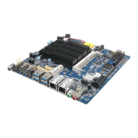
Page 16: Product Overview
EMX-APLP-34 User’s Manual 2.1 Product Overview 16 EMX-APLP-34 User’s Manual... - Page 17 User’s Manual EMX-APLP-34 User’s Manual 17...
-
Page 18: Jumper And Connector List
3 x 1 header, pitch 2.00mm CMOS1 Clear CMOS Connectors Label Function Note CPU fan connector 4 x 1 wafer, pitch 2.54mm FAN1 FPT1/2 Front Panel connector 1/2 5 x 2 header, pitch 2.54mm DIMM1/2 204-pin DDR3L DIMM socket 18 EMX-APLP-34 User’s Manual... - Page 19 5 x 2 header, pitch 2.00mm DC Power-in connector DCIN1 I2C connector 5 x 1 header, pitch 2.00mm I2C1 HDMI connector HDMI1 Line-out audio jack LOUT1 Mic-in audio jack MIC1 Digital Microphone connector 5 x 1 header, pitch 2.54mm DMIC1 EMX-APLP-34 User’s Manual 19...
- Page 20 EMX-APLP-34 User’s Manual SIM card slot SIM1 20 EMX-APLP-34 User’s Manual...
-
Page 21: Setting Jumpers & Connectors
* Default 2.3.2 SATA2/MSATA1 mPCIe slot selector (JMSW1) SATA2 Connector* (SATA2 Connector enabled, MSATA1 slot Disabled) MSATA1 mPCIe slot (MSATA1 slot enabled, SATA2 Connector Disabled) * Default Note: SATA2/MSATA1 shared SATA signal, can not be used simultaneously. EMX-APLP-34 User’s Manual 21... -
Page 22: Lvds Back Light Power Selection (Jsbkl1)
EMX-APLP-34 User’s Manual 2.3.3 LVDS Back Light power selection (JSBKL1) PWM Mode*(Max current: 2A) DC Mode(Max current: 2A) * Default 2.3.4 AT/ATX Power Mode Select (JSATX1) ATX* * Default 22 EMX-APLP-34 User’s Manual... -
Page 23: Clear Cmos (Cmos1)
User’s Manual 2.3.5 Clear CMOS (CMOS1) Protect* Clear CMOS * Default 2.3.6 LCD Inverter connector (JBKL1) Signal +12V LVDS_BKLTEN LVDS_BKLADJ EMX-APLP-34 User’s Manual 23... -
Page 24: Serial Port 1 Connector (Com1)
2.3.7 Serial port 1 connector (COM1) Signal PIN PIN Signal NDCDA# NRXDA NTXDA NDTRA# NDSRA# NRTSA# NCTSA# NRIA# 2.3.8 Serial port 2 connector (COM2) Signal PIN PIN Signal NDCDB# NRXDB NTXDB NDTRB# NDSRB# NRTSB# NCTSB# NRIB# 24 EMX-APLP-34 User’s Manual... -
Page 25: Serial Port 3 Connector (Com3)
2.3.9 Serial port 3 connector (COM3) Signal PIN PIN Signal NDCDC# NRXDC NTXDC NDTRC# NDSRC# NRTSC# NCTSC# NRIC# 2.3.10 Serial port 4 connector (COM4) Signal PIN PIN Signal NDCDD# NRXDD NTXDCD NDTRD# NDSRD# NRTSD# NCTSD# NRID# EMX-APLP-34 User’s Manual 25... -
Page 26: Serial Port 6 Connector (Com6)
2.3.11 Serial port 6 connector (COM6) Signal PIN PIN Signal NDCDF# NRXDF NTXDCF NDTRF# NDSRF# NRTSF# NCTSF# NRIF# 2.3.12 Serial port 5 connector (COM5) Signal PIN PIN Signal NDCDE# NRXDE NTXDCE NDTRE# NDSRE# NRTSE# NCTSE# NRIE# 26 EMX-APLP-34 User’s Manual... -
Page 27: Serial Port 1 Rs485/422 Mode Connector (Jrs485)
User’s Manual 2.3.13 Serial Port 1 RS485/422 Mode connector (JRS485) Signal PIN PIN Signal 485TX- 422RX- 485TX+ 422RX+ 2.3.14 General purpose I/O connector (DIO1) Signal PIN PIN Signal SMB_CLK SMB_DATA EMX-APLP-34 User’s Manual 27... -
Page 28: Sata Power Connector 1/2 (Spwr1/2)
EMX-APLP-34 User’s Manual 2.3.15 SATA Power connector 1/2 (SPWR1/2) SPWR1 Signal SPWR2 +12 V 2.3.16 Power connector (PWR1) Signal Signal +V12-24_DCIN +V12-24_DCIN 28 EMX-APLP-34 User’s Manual... -
Page 29: Usb2.0 Connector (Usb3)
User’s Manual 2.3.17 USB2.0 connector (USB3) Signal Signal +V5A_USB45 +V5A_USB45 USBDN4 USBDN5 USBDP4 USBDP5 2.3.18 USB2.0 connector (USBH1) Signal PIN PIN Signal +V5A_USB_H12 +V5A_USB_H12 USB_HDN1 USB_HDN2 USB_ HDP1 USB_ HDP2 EMX-APLP-34 User’s Manual 29... -
Page 30: Usb2.0 Connector (Usbh2)
EMX-APLP-34 User’s Manual 2.3.19 USB2.0 connector (USBH2) Signal USB_ HDP4 USB_HDN4 +V5A_USB_H12 2.3.20 Battery connector (BT1) Signal + V3.3A 30 EMX-APLP-34 User’s Manual... -
Page 31: Lvds Connector (Lvds1)
12 LVDS_DATAN0 LVDS_DATAP3 15 16 LVDS_DATAP2 LVDS_DATAN3 17 18 LVDS_DATAN2 LVDS_DATAP5 21 22 LVDS_DATAP4 LVDS_DATAN5 23 24 LVDS_DATAN4 LVDS_DATAP7 27 28 LVDS_DATAP6 LVDS_DATAN7 29 30 LVDS_DATAN6 LVDS_CLK2P LVDS_CLK1P LVDS_ CLK2N LVDS_ CLK1N LVDS_VDD12V 39 40 LVDS_VDD12V EMX-APLP-34 User’s Manual 31... -
Page 32: Front Audio Connector (Faud1)
Front Audio connector (FAUD1) Signal PIN PIN Signal LINE2_JD LINE2_L SENSE_B_JD3 MIC2_JD LINE2_R AUD_FRONT_DET MIC2_R MIC2_L 3.3.22.1 Signal Description –Front Audio connector (FAUD1) Signal Signal Description LINE2_JD AUDIO IN (LINE_RIN/LIN)sense pin MIC2_JD MIC IN (MIC_RIN/LIN) sense pin 32 EMX-APLP-34 User’s Manual... -
Page 33: Lpc Connector (Jlpc1)
User’s Manual 2.3.23 LPC connector (JLPC1) Signal PIN PIN Signal LPC_AD0 +3.3V LPC_AD1 PLT_RST# LPC_AD2 LPC_FRAME# LPC_AD3 LPC_CLK_DEB LPC_SERIRQ 2.3.24 EC_Program (EC1) Signal PIN PIN Signal +3.3A_ECSPI EC_FSCE# EC_FSCK EC_FSMIOSO EC_FSMOSI EC_HOLD# EC_SMBCLK EC_SMBDATA EMX-APLP-34 User’s Manual 33... -
Page 34: Spi Connector (Spi1)
EMX-APLP-34 User’s Manual 2.3.25 SPI connector (SPI1) Signal PIN PIN Signal +V1.8A_SPI SPI_CS0# SPI_CLK SPI_MISO SPI_MOSI SPI_HOLD# 2.3.26 Sony/Philips Digital Interface (SPDIF1) Signal SPDIF_OUT 34 EMX-APLP-34 User’s Manual... -
Page 35: Speaker Connector (Spk1)
User’s Manual 2.3.27 Speaker connector (SPK1) Signal RSPK- RSPK+ LSPK- LSPK+ 2.3.28 Front Panel connector 1 (FPT1) Signal PIN PIN Signal +HD_LED +PWR_LED -HD_LED -PWE_LED +Reset +PWR_BNT -Reset -PWR_BNT EMX-APLP-34 User’s Manual 35... -
Page 36: Front Panel Connector 2 (Fpt2)
2. BLK_UP with GND/BLK_DN with GND: Step control LVDS Backlight by use button and BIOS must to be set “BR Button”. (Please refer to page.61) 2.3.30 LED indicator connector 1 (LED1) Signal LED_LAN1_LINK_2500# LED_LAN1_LINK1000# LED_LAN1_ACT_N LED_LAN1_ACT_P 36 EMX-APLP-34 User’s Manual... -
Page 37: Led Indicator Connector 2 (Led2)
User’s Manual 2.3.31 LED indicator connector 2 (LED2) Signal LED_LAN2_LINK_2500# LED_LAN2_LINK1000# LED_LAN2_ACT_N LED_LAN2_ACT_P 2.3.32 CPU fan connector (FAN1) Signal +12V CPU_FANIN CPU_FANOUT EMX-APLP-34 User’s Manual 37... -
Page 38: Digital Microphone Connector (Dmic1)
EMX-APLP-34 User’s Manual 2.3.33 Digital Microphone connector (DMIC1) Signal DMIC_CLK DMIC_DAT +V3.3A 2.3.34 eDP connector (EDP1) Signal PIN PIN Signal EDP_TXN0 EDP_TXN3 EDP_TXP0 EDP_TXP3 EDP_TXN1 EDP_TXP1 EDP_AUXN EDP_AUXP EDP_TXN2 EDP_TXP2 EDP_C_HPD EDP_VCC_PAL 19 20 EDP_VCC_PAL 38 EMX-APLP-34 User’s Manual... -
Page 39: I2C Connector (I2C1)
User’s Manual 2.3.35 I2C connector (I2C1) Signal +3.3V I2C5_INT# I2C5_LS_CLK I2C5_LS_DATA EMX-APLP-34 User’s Manual 39... -
Page 40: Bios Setup
EMX-APLP-34 User’s Manual 3.BIOS Setup 40 EMX-APLP-34 User’s Manual... -
Page 41: Introduction
If you do not press the keys at the correct time and the system does not boot, an error message will be displayed and you will again be asked to. Press F1 to Continue, DEL to enter SETUP EMX-APLP-34 User’s Manual 41... -
Page 42: Using Setup
Note: Some of the navigation keys differ from one screen to another. To Display a Sub Menu Use the arrow keys to move the cursor to the sub menu you want. Then press <Enter>. A “” pointer marks all sub menus. 42 EMX-APLP-34 User’s Manual... -
Page 43: Getting Help
BIOS Vendor and your systems manufacturer to provide the absolute maximum performance and reliability. Even a seemingly small change to the chipset setup has the potential for causing you to use the override. EMX-APLP-34 User’s Manual 43... -
Page 44: Bios Setup
<Enter> to accept and enter the sub-menu. 3.6.1 Main Menu This section allows you to record some basic hardware configurations in your computer and set the system clock. 44 EMX-APLP-34 User’s Manual... -
Page 45: System Language
Visit the Avalue website (www.avalue.com.tw) to download the latest product and BIOS information. 3.6.2 Advanced Menu This section allows you to configure your CPU and other system devices for basic operation through the following sub-menus. EMX-APLP-34 User’s Manual 45... -
Page 46: Trusted Computing
O.S. will not show Security Device. TCG EFI Enable[Default] protocol and INT1A interface will not be available. 3.6.2.2 ACPI Settings Item Options Description Enable ACPI Auto Disabled[Default], Enables or Disables BIOS ACPI Auto Configuration Enabled Configuration. 46 EMX-APLP-34 User’s Manual... -
Page 47: It8528 Super Io Configuration
Wake Up by Ring from S3/S4/S5. Enabled[Default], 3.6.2.3 IT8528 Super IO Configuration You can use this item to set up or change the IT8528 Super IO configuration for serial ports. Please refer to 3.6.2.3.1~ 3.6.2.3.6 for more information. EMX-APLP-34 User’s Manual 47... -
Page 48: Serial Port 1 Configuration
Set Parameters of Serial Port 6 (COMF). 3.6.2.3.1 Serial Port 1 Configuration Item Option Description Disabled Serial Port Enable or Disable Serial Port (COM) Enabled[Default], UART 232[Default], UART 232 422 485 UART 422 Change the Serial Port as RS232/422/485 UART 485 48 EMX-APLP-34 User’s Manual... -
Page 49: Serial Port 2 Configuration
3.6.2.3.2 Serial Port 2 Configuration Item Option Description Enabled[Default], Serial Port Enable or Disable Serial Port (COM) Disabled 3.6.2.3.3 Serial Port 3 Configuration Item Option Description Disabled Serial Port Enable or Disable Serial Port (COM) Enabled[Default], EMX-APLP-34 User’s Manual 49... -
Page 50: Serial Port 4 Configuration
3.6.2.3.4 Serial Port 4 Configuration Item Option Description Disabled Serial Port Enable or Disable Serial Port (COM) Enabled[Default], 3.6.2.3.5 Serial Port 5 Configuration Item Option Description Disabled Serial Port Enable or Disable Serial Port (COM) Enabled[Default], 50 EMX-APLP-34 User’s Manual... -
Page 51: Serial Port 6 Configuration
User’s Manual 3.6.2.3.6 Serial Port 6 Configuration Item Option Description Disabled Serial Port Enable or Disable Serial Port (COM) Enabled[Default], 3.6.2.4 H/W Monitor Item Options Description Disabled[Default], Smart Fan Function Enable or Disable Smart Fan Enabled EMX-APLP-34 User’s Manual 51... -
Page 52: S5 Rtc Wake Settings
Select FixedTime, system will wake on Wake system from S5 Fixed Time the hr::min::sec specified. Select Dynamic Dynamic Time Time, System will wake on the current time + Increase minute(s) 3.6.2.6 Serial Port Console Redirection 52 EMX-APLP-34 User’s Manual... -
Page 53: Legacy Console Redirection Settings
Console Redirection is disabled before booting to legacy OS. When Always Enable is Always Enable[Default], Redirect After POST selected, then Legacy BootLoader Console Redirection is enabled for legacy OS. Default setting for this option is set to Always Enable. EMX-APLP-34 User’s Manual 53... -
Page 54: Cpu Configuration
PROCHOT# to throttle the processor. Disabled, Thermal Monitor Enable/Disable Thermal Monitor Enabled[Default] Disabled, Monitor Mwait Enabled Enable/Disable Monitor Mwait. Auto[Default] HW_ALL[Default] P-STATE Coordination SW_ALL Change P-STATE Coordination type SW_ANY Disabled[Default], Enable/Disable Digital Thermal Sensor. Enabled 54 EMX-APLP-34 User’s Manual... -
Page 55: Socket 0 Cpu Information
User’s Manual 3.6.2.7.1 Socket 0 CPU Information 3.6.2.7.2 CPU Power Management Configuration Item Options Description Disabled, EIST Enable/Disable Intel SpeedStep Enabled[Default] Disabled, Turbo Mode Turbo Mode. Enabled[Default] Disabled, C-States Enable/Disable C State Enabled[Default] EMX-APLP-34 User’s Manual 55... -
Page 56: Usb Configuration
XHCI driver. Disabled Enable/Disable USB Mass Storage Driver USB Mass Storage Driver Support Enabled[Default] Support. 1 sec The time-out value for Control, Bulk, and Interrupt USB transfer time-out 5 sec transfers. 10 sec 56 EMX-APLP-34 User’s Manual... -
Page 57: Network Stack Configuration
Optical drives are emulated as ‘CDROM’, KingstonDataTraveler 3.0PMAP Forced FDD Hard Disk drives with no media will be emulated according CD-ROM to a drive type. 3.6.2.9 Network Stack Configuration Item Options Description Disabled[Default] Network Stack Enable/Disable UEFI Network Stack Enabled EMX-APLP-34 User’s Manual 57... -
Page 58: Csm Configuration
EMX-APLP-34 User’s Manual 3.6.2.10 CSM Configuration Item Options Description Disabled[Default], CSM Support Enable/Disable CSM Support. Enabled 3.6.2.11 NVMe Configuration 58 EMX-APLP-34 User’s Manual... -
Page 59: Security Configuration
TXE HMRFPO TXE HMRFPO Disabled[Default] Enabled[Default], TXE EOP Message Send EOP Message Before Enter OS Disabled 3.6.2.13 System Component Item Options Description Warm Reset[Default], OS Reset Select Select the reset type in FACP table Cold Reset EMX-APLP-34 User’s Manual 59... -
Page 60: Chipset
2.25 GB Max TOLUD Maximum Value of TOLUD. 2.5 GB 2.75 GB Enable/Disable above 4GB MemoryMappedIO Above 4GB MMIO BIOS Enabled, BIOS assignment This is disabled automatically assignment Disabled[Default] when Aperture Size is set to 2048MB. 60 EMX-APLP-34 User’s Manual... -
Page 61: South Bridge
User’s Manual 3.6.3.2 South Bridge Item Option Description Quiet Serial IRQ Mode Configure Serial IRQ Mode. Continuous[Default] Windows[Default] OS Selection Android Select the target OS. Intel Linux 3.6.3.3 Uncore Configuration EMX-APLP-34 User’s Manual 61... - Page 62 BR Button LVDS Brightness Control Method. 1.BIOS Brightness Control Method 2.OS Driver OS Driver LVDS Back Light PWM Select LVDS back light PWM duty. 100%[Default] 200[Default] LVDS Back Light PWM Select LVDS back light PWM Frequency. Frequency 62 EMX-APLP-34 User’s Manual...
-
Page 63: South Cluster Configuration
User’s Manual 3.6.3.4 South Cluster Configuration 3.6.3.4.1 HD-Audio Configuration Item Option Description Disable[Default], HD-Audio Support Enable/Disable HD-Audio Support Enable EMX-APLP-34 User’s Manual 63... -
Page 64: Pci Express Configuration
EMX-APLP-34 User’s Manual 3.6.3.4.2 PCI Express Configuration Item Option Description Disabled[Default], Compliance Mode Compliance Mode Enable/Disable Enabled PCIe slot[Default], PCIe port5-Slot or M.2 select PCIe port5 mapping to PCIe slot or M.2 3.6.3.4.2.1 PCI Express Root Port 3(i225/i226) 64 EMX-APLP-34 User’s Manual... -
Page 65: Pci Express Root Port 4(I225/I226)
Control the PCI Express Root Port. Auto: To PCI Express Root Port 4 Disable disable unused root port automatically for the (i225/i226) Enable[Default], most optimum power savings. Enable: Enable PCIe root port Disable: Disable PCIe root port EMX-APLP-34 User’s Manual 65... -
Page 66: Pci Express Root Port 5(M.2/Pcie Slot)
Enable: Enable PCIe root port Disable: Disable PCIe root port Disable[Default] PCI Express Active State Power Management ASPM settings L0sL1 Auto Disabled[Default] L1.1 L1 Substates PCI Express L1 Substates settings. L1.2 L1.1 & L1.2 66 EMX-APLP-34 User’s Manual... -
Page 67: Pci Express Root Port 6(Mpcie)
PCIe root port Disable: Disable PCIe root port Disable[Default] PCI Express Active State Power Management ASPM settings L0sL1 Auto Disabled[Default] L1.1 L1 Substates PCI Express L1 Substates settings. L1.2 L1.1 & L1.2 Auto[Default] PCIe Speed Gen 1 Configure PCIe Speed Gen 2 EMX-APLP-34 User’s Manual 67... -
Page 68: Sata Drives
Identify the SATA port is connected to Solid SATA Device Type Solid State Drive State Driver or Hard Disk Drive Disabled[Default] Enable/Disable SATA Port 0/1 DevSlp. Board SATA Port 0/1 DevSlp Enabled rework for LP needed before enable. 68 EMX-APLP-34 User’s Manual... -
Page 69: Scc Configuration
User’s Manual 3.6.3.4.4 SCC Configuration Item Option Description Disable[Default], SCC eMMC Support (D28:F0) Enable/Disable SCC eMMC Support. Enable 3.6.3.4.5 USB Configuration Item Option Description Enable, XHCI Pre-Boot Driver Enable/Disable XHCI Pre-Boot Driver support. Disable[Default] EMX-APLP-34 User’s Manual 69... -
Page 70: Security
EMX-APLP-34 User’s Manual 3.6.4 Security Setup Administrator Password Set setup Administrator Password User Password Set User Password 3.6.4.1 Secure Boot 70 EMX-APLP-34 User’s Manual... -
Page 71: Secure Boot
Secure Boot Mode –Custom_Standard, Set UEFI Standard[Default] Secure Boot Mode to STANDARD mode or CUSTOM Secure Boot Mode Customized mode, this change is effect after save. And after reset, the mode will return to STANDARD mode. 3.6.4.1.1 Secure Boot EMX-APLP-34 User’s Manual 71... -
Page 72: Boot
65535(0xFFFF) means Setup Prompt Timeout indefinite waiting. On[Default] Bootup NumLock State Select the Keyboard NumLock state Disabled[Default] Quiet Boot Enables or disables Quiet Boot option Enabled Boot Option #1 Set the system boot order 72 EMX-APLP-34 User’s Manual... -
Page 73: Save And Exit
Reset the system after saving the changes. 3.6.6.2 Discard Changes and Reset Any changes made to BIOS settings during this session of the BIOS setup program are discarded. The setup program then exits and reboots the controller. EMX-APLP-34 User’s Manual 73... -
Page 74: Restore Defaults
This option restores all BIOS settings to the factory default. This option is useful if the controller exhibits unpredictable behavior due to an incorrect or inappropriate BIOS setting. 3.6.6.4 Launch EFI Shell from filesystem device Attempts to Launch EFI Shell application (Shellx64.efi) from one of the available filesystem devices. 74 EMX-APLP-34 User’s Manual... -
Page 75: Drivers Installation
User’s Manual 4. Drivers Installation Note: Installation procedures and screen shots in this section are for your reference and may not be exactly the same as shown on your screen. EMX-APLP-34 User’s Manual 75... -
Page 76: Install Chipset Driver
Windows 10 operation system. If the warning message appears while the installation process, click Continue to go on. Step 3. Click Install. Step1. Click Next. Step 4. Click Finish to complete setup. Step 2. Click Accept. 76 EMX-APLP-34 User’s Manual... -
Page 77: Install Vga Driver
Continue to go on. Step 3. Click Next. Step 1. Click Next to continue installation. Step 4. Click Next. Step 2. Step 5. Click Finish to complete setup. Click Yes to accept license agreement. EMX-APLP-34 User’s Manual 77... -
Page 78: Install Txe Driver
If the warning message appears while the installation process, click Continue to go on. Step 1. Click Next to continue setup. Step 3. Click Next. Step 2. Click Next. Step 4. Click Finish to complete the setup. 78 EMX-APLP-34 User’s Manual... -
Page 79: Install Audio Driver (For Realtek Alc888S Hd Audio)
Windows 10 operation system. If the warning message appears while the installation process, click Continue to go on. Step1. Click Next to Install. Step 2. Select Finish to complete Installation. EMX-APLP-34 User’s Manual 79... -
Page 80: Install Lan Driver (For Intel I226Lm)
Continue to go on. Step 3. Click Next. Step 1. Click Install Drivers and Step 4. Click Install. Software. Step 5. Click Finish to complete the setup. Step 2. Click Next. 80 EMX-APLP-34 User’s Manual... -
Page 81: Mechanical Drawing
User’s Manual 5. Mechanical Drawing EMX-APLP-34 User’s Manual 81... - Page 82 EMX-APLP-34 User’s Manual Unit: mm 82 EMX-APLP-34 User’s Manual...
- Page 83 User’s Manual Unit: mm EMX-APLP-34 User’s Manual 83...
Need help?
Do you have a question about the EMX-APLP-34 and is the answer not in the manual?
Questions and answers