
Related Manuals for Avalue Technology EMX-QM77


Summary of Contents for Avalue Technology EMX-QM77
- Page 1 EMX-QM77 Intel® QM77 with Intel Core™ i7/ i5/ i3 Pentium/Celeron Mobile CPU Mini-ITX Motherboard User’s Manual 1st Ed – 23 July 2012 Part No. E2047EMXQ00R...
- Page 2 Disclaimer Avalue Technology Inc. reserves the right to make changes, without notice, to any product, including circuits and/or software described or contained in this manual in order to improve design and/or performance. Avalue Technology assumes no responsibility or liability for the use of the described product(s), conveys no license or title under any patent, copyright, or 2 EMX-QM77 User’s Manual...
- Page 3 Whether your new Avalue device is destined for the laboratory or the factory floor, you can be assured that your product will provide the reliability and ease of operation for which the name Avalue has come to be known.
- Page 4 Our dealers are well trained and ready to give you the support you need to get the most from your Avalue’s products. In fact, most problems reported are minor and are able to be easily solved over the phone.
- Page 5 If any of Avalue’s products is defective, it will be repaired or replaced at no charge during the warranty period. For out-of-warranty repairs, you will be billed according to the cost of replacement materials, service time, and freight.
-
Page 6: Table Of Contents
PCI Express x16 slot .......................... 34 2.7.4 MINI PCI Express ..........................34 2.7.5 CFast Card ............................35 Jumper settings and Connectors ................36 2.8.1 Clear CMOS (JCMOS1) ........................36 2.8.2 COM2, COM3, RI/+5V/+12V Select (JCOMPWR2 JCOMPWR3 ) ..........37 6 EMX-QM77 User’s Manual... - Page 7 USB Configuration ......................... 63 3.4.12 Super IO Configuration ........................64 3.4.12.1 Serial Port 1 configuration ....................... 65 3.4.12.2 Serial Port 2 configuration ....................... 66 3.4.12.3 Serial Port 3 configuration ....................... 67 3.4.13 Smart Fan Mode Configuration ....................68 EMX-QM77 User’s Manual 7...
- Page 8 3.4.16.1.1 LCD Control ............................ 74 3.4.16.1.2 NB PCIe Configuration ........................77 3.4.17 Memory Configuration ........................79 3.4.18 PCH-IO Configuration ........................80 3.4.19 USB Configuration ......................... 82 3.4.20 Boot ..............................83 3.4.21 Security ............................84 3.4.22 Save & Exit ............................ 85 8 EMX-QM77 User’s Manual...
-
Page 9: Getting Started
1.2 Packing List Before you begin installing your single board, please make sure that the following materials have been shipped: 1 x EMX-QM77 Mini-ITX Motherboard 1 x CD-ROM contains OS drivers/QIG/User’s Manual ... -
Page 10: Document Amendment History
EMX-QM77 User’s Manual 1.3 Document Amendment History Revision Date Comment July 2012 Initial Release 10 EMX-QM77 User’s Manual... -
Page 11: Manual Objectives
We strongly recommend that you study this manual carefully before attempting to interface with EMX-QM77 series or change the standard configurations. Whilst all the necessary information is available in this manual we would recommend that unless you are confident, you contact your supplier for guidance. -
Page 12: System Specifications
Realtek AL892, 5.1 Channel HD Audio Audio Codec Line-in, line-out, Mic-in, S/PDIF Out, Front Audio Header Audio Interface Ethernet Intel 82579LM GbE LAN supports iAMT 8.0 LAN1 Intel 82583V GbE LAN LAN2 Back Panel I/O Port 12 EMX-QM77 User’s Manual... - Page 13 0°C to 60°C (32°F to 140°F) Operating Temperature 0% to 90% relative humidity, non-condensing Operating Humidity 6.69" x 6.69" (170 x 170mm) Size (L x W) 0.77 lbs (0.35 Kg) Weight * Specifications are subject to change without notice. EMX-QM77 User’s Manual 13...
-
Page 14: Architecture Overview - Block Diagram
EMX-QM77 User’s Manual 1.6 Architecture Overview – Block Diagram The following block diagram shows the architecture and main components of EMX-QM77. 14 EMX-QM77 User’s Manual... -
Page 15: Hardware Configuration
EMX-QM77 User’s Manual 2. Hardware Configuration EMX-QM77 User’s Manual 15... -
Page 16: Product Overview
- Windows 7 32 bit / 64 bit - Fedora core Linux16 32bit / 64 bit -Red Hat Enterprise Linux 6.0 i386vg 2.1.2 Key Architecture Features • Supports Intel rPGA988 CPU, the 3’rd Generation Intel® Core i3, i5, i7 Mobile processors. 16 EMX-QM77 User’s Manual... - Page 17 - Five SATA ports (2 port of SATA 3.0 and 3 ports of SATA II) support RAID 0,1, 5, 10 - Gigabit Ethernet Media Access Controller (GbE MAC) IPv4 and IPv6 Checksum Offload - High Definition Audio - USB: 3.0, up to 4 ports - USB: 2.0, up to 8 ports EMX-QM77 User’s Manual 17...
-
Page 18: Before You Proceed
When installing the motherboard, make sure that you place it into the chassis in the correct orientation. The edge with external ports goes to the rear part of the chassis as indicated in the image below. 18 EMX-QM77 User’s Manual... -
Page 19: Screw Holes
Place four (4) screws into the holes indicated by circles to secure the motherboard to the chassis. Place this side towards the rear of the chassis. Do not over tighten the screws! Doing so can damage the motherboard. EMX-QM77 User’s Manual 19... -
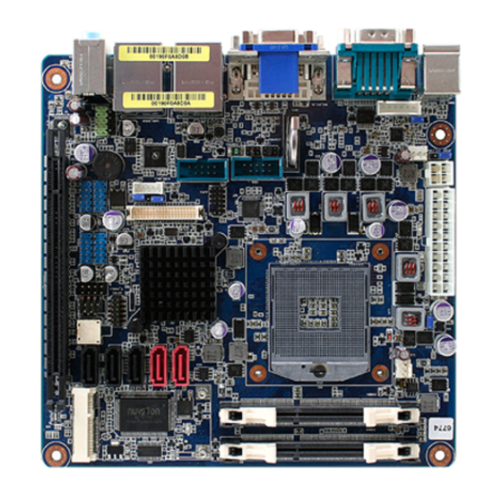
Page 20: Motherboard Layout
EMX-QM77 User’s Manual 2.3.3 Motherboard Layout 20 EMX-QM77 User’s Manual... -
Page 21: Jumper And Connector List
HDMI 1.3 19-pin LAN1USB12 RJ-45 Ethernet Connector x 1 USB 2.0 Connector x 2 LAN2USB34 RJ-45 Ethernet Connector x 1 USB 2.0 Connector x 2 Audio1 Audio Line-In , Line-Out , Mic.-In 5.1 Channel Audio I/O (3 jacks) EMX-QM77 User’s Manual 21... -
Page 22: Internal Connectors
1 x 4 header SATA1 ~ 5 SATA Data Connector * 5 7P Male connector ATX12V ATX Power Connector 2x2 pin power connector USB56 USB78 USB Connector * 8 5 x 2 header, pitch 2.54mm USB910 USB1112 22 EMX-QM77 User’s Manual... -
Page 23: Central Processing Unit (Cpu)
Contact your retailer immediately if the PnP cap is missing, or if you see any damage to the PnP cap/socket pins/motherboard components. Avalue will shoulder the cost of repair only if the damage is shipment/transit-related. ... -
Page 24: Installing The Cpu
2.5.1.1 Locate the CPU socket on the motherboard. Before installing the CPU, make sure that the socket box is facing towards you and the load lever is on your left. 2.5.1.2 Separate CPU cooler and its base first by screw drawer 24 EMX-QM77 User’s Manual... - Page 25 EMX-QM77 User’s Manual 1. Assemble the CPU FAN retention module 2. Position the CPU over the socket, making sure that the gold triangle is the same side as CPU Socket triangle CPU Socket triangle Gold triangle EMX-QM77 User’s Manual 25...
- Page 26 3. turn the CPU lock clockwise to lock CPU The CPU fits in only one correct orientation. DO NOT force the CPU into the socket to prevent bending the connectors on the socket and damaging the CPU! 26 EMX-QM77 User’s Manual...
-
Page 27: Installing The Cpu Heatsink And Fan
Screw tightly the four fasteners. Connect the CPU fan cable to the connector on the motherboard labeled CPU_FAN. Do not forget to connect the CPU fan connector! Hardware monitoring errors can occur if you fail to plug this connector. EMX-QM77 User’s Manual 27... -
Page 28: System Memory
204-pin DDR2 DIMM. DDR3 DIMMs are notched differently to prevent installation on a DDR2 DIMM socket. The following figure illustrates the location of the sockets: 204-pin DDR3 DIMM sockets Channel Socket Channel A DIMMA1 Channel B DIMMB1 28 EMX-QM77 User’s Manual... -
Page 29: Memory Configurations
Due to CPU limitation, DIMM modules with 128 Mb memory chips or double-sided x16 memory chips are not supported in this motherboard. 2.6.3 Installing a SO-DIMM Unlock a DIMM socket by pressing the retaining clips outward. EMX-QM77 User’s Manual 29... - Page 30 Align a SO-DIMM on the socket such that the notch on the SO-DIMM matches the break on the socket. DDR3 SO-DIMM notch Unlocked retaining clip Firmly insert the SO-DIMM into the socket until the retaining clips snap back in place and the SO-DIMM is properly seated. 30 EMX-QM77 User’s Manual...
- Page 31 EMX-QM77 User’s Manual Locked retaining clip EMX-QM77 User’s Manual 31...
-
Page 32: Removing A So-Dimm
1. Simultaneously press the retaining clips downward to unlock the DIMM. 2. Remove the DIMM from the socket. Unlocked retaining clip Support the SO-DIMM lightly with your fingers when pressing the retaining clips. The SO-DIMM might get damaged when it flips out with extra force. 32 EMX-QM77 User’s Manual... -
Page 33: Expansion Card
1. Turn on the system and change the necessary BIOS settings, if any. See Chapter 2 for information on BIOS setup. 2. Assign an IRQ to the card if needed. Refer to the tables on the next page. 3. Install the software drivers for the expansion card. EMX-QM77 User’s Manual 33... -
Page 34: Pci Express X16 Slot
This motherboard supports one PCI Express x16. The following figure shows a graphics card installed on the PCI Express x16 slot. 2.7.4 MINI PCI Express This motherboard supports one MINI PCI Express. The following figure shows a Decode card installed on the MINI PCI Express slot. 34 EMX-QM77 User’s Manual... -
Page 35: Cfast Card
EMX-QM77 User’s Manual 2.7.5 CFast Card This motherboard supports one CFast Card connector and its location is on button side of MB. The following figure shows a CFast Card installed on the CFast Card connector.. EMX-QM77 User’s Manual 35... -
Page 36: Jumper Settings And Connectors
You do not need to clear the RTC when the system hangs due to overclocking. For system failure due to overclocking, use the C.P.R. (CPU Parameter Recall) feature. Shut down and reboot the system so the BIOS can automatically reset parameter settings to default values. 36 EMX-QM77 User’s Manual... -
Page 37: Com2, Com3, Ri/+5V/+12V Select (Jcompwr2 Jcompwr3 )
This jumper allows you to select the power mode of COM PORTATX Mode or AT mode RI (Default) +12V 2.8.3 LVDS Back Light power selection (JLVDS_BKL1) +5V (Default) +3.3V Function: Voltage Level shift select for Bright control@LVDS EMX-QM77 User’s Manual 37... -
Page 38: At/Atx Power Mode Select (Jpson)
6. DVI-D port This 29-pin DVI-D port connect is for a DVI monitor. 7. LAN (RJ-45) port. This port allows Gigabit connection to a Local Area Network (LAN) through a network hub. Refer to the table below for the LAN port LED indications. 38 EMX-QM77 User’s Manual... -
Page 39: Cpu And System Fan Connectors (Cpu_Fan1, Sys_Fan1)
Do not forget to connect the fan cables to the fan connectors. Insufficient air flow inside the system may damage the motherboard components. These are not jumpers! DO NOT place jumper caps on the fan connectors. EMX-QM77 User’s Manual 39... -
Page 40: System Panel (F_Panel)
Hard Disk Drive Activity LED (Pin 1-3 HDLED) This 2-pin connector is for the HDD Activity LED. Connect the HDD Activity LED cable to this connector. The IDE LED lights up or flashes when data is read from or written to the HDD. 40 EMX-QM77 User’s Manual... -
Page 41: Atx Power Connectors (Atxpwr, Atx12V1)
The connector is for ATX power supply plugs. The power supply plugs are designed to fit these connectors in only one orientation. Find the proper orientation and push down firmly until the connectors completely fit. ATXPWR1 ATX12V1 EMX-QM77 User’s Manual 41... -
Page 42: Serial Port Connectors (Com2, Com3)
COM2 , COM3 1.DCD 6.DSR 2.RXD 7.RTS 3.TXD 8.CTS 4.DTR 9.RI/PWR 5.GND 2.8.10 GPIO Connector (JGPIO) This connector is for GPIO function. JGPIO 1.SIO_GPIO0 2.SIO_GPIO4 3.SIO_GPIO1 4.SIO_GPIO5 5.SIO_GPIO2 6.SIO_GPIO6 7.SIO_GPIO3 8.SIO_GPIO7 9.SMB_CLK_RESUME 10.SMB_DAT_RESUME 11.GND 12.VCC GPIO 42 EMX-QM77 User’s Manual... -
Page 43: Audio Mic.-In & Line-Out Connector (Fpaud1)
Jack detection for MIC FIO_SENSE Jack detection for FIO For motherboards with the optional HD Audio feature, we recommend that you connect a high-definition front panel audio module to this connector to avail of the motherboard’s high‑definition audio capability. EMX-QM77 User’s Manual 43... -
Page 44: Lvds Connector (Lvds1)
35.LVDS_B_CK- 36.LVDS_A_CK- 33.LVDS_B_CK+ 34.LVDS_A_CK+ 31.GND 32.GND 29.LVDS_B3- 30.LVDS_B2- 27.LVDS_B3+ 28.LVDS_B2+ 25.GND 26.GND 23.LVDS_B1- 24.LVDS_B0- 21.LVDS_B1+ 22.LVDS_B0+ 19.GND 20.GND 17.LVDS_A3- 18.LVDS_A2- 15.LVDS_A3+ 16.LVDS_A2+ 13.GND 14.GND 11.LVDS_A1- 12.LVDS_A0- 9.LVDS_A1+ 10.LVDS_A0+ 7.GND 8.GND 5.I2C_CLK 6.I2C_DATA 3.VDD(+3.3V) 4.VDD(+5V) 1.VDD(+3.3V) 2.VDD(+5V) 44 EMX-QM77 User’s Manual... -
Page 45: Lcd Inverter Connector (Jbkl)
Signal Description Signal Signal Description For inverter with adjustable Backlight function, it is possible to control the LCD brightness through the VR signal. JLVDS_JBKL Vadj=0.75V ~ 4.25V (Recommended: 4.7KΩ, > 1/16W) ENBKL LCD backlight ON/OFF control signal EMX-QM77 User’s Manual 45... -
Page 46: Spi Connector (Jpi_Cn1)
OC-192 (10 Gb/s) and beyond, enabling them to dramatically increase system performance. SPI_CN1 1.+3.3V 2.GND 3.SP1_CS# 4.SPI_CLK 5.SPI_MISO 6.SPI_MOSI 7.NC 8.NC 2.8.15 LPC Connector (JLPC) JLPC 1.NC 2.+3.3 3.LPC_AD3 4.PRST_SIO# 5.LPC_AD1 6.LPC_AD2 7.LPC_FRAME# 8.LPC_AD0 10.GND 11.CLK33M_LPC 12.GND 46 EMX-QM77 User’s Manual... -
Page 47: Serial Ata 3 Connector (Sata1, Sata2)
SATA3、SATA4、SATA5 Connect the right-angle side of SATA signal cable to SATA device. Or you may connect the right-angle side of SATA cable to the onboard SATA port to avoid mechanical conflict with large graphics cards. EMX-QM77 User’s Manual 47... -
Page 48: Usb Connectors (Usb56, Usb78, Usb910, Usb1112,)
These USB connectors comply with USB 2.0 specification that supports up to 480 Mbps connection speed. USB56, USB78, USB910, USB1112 9.NC 8.GND 7.GND 6.USB+ 5.USB+ 4.USB- 3.USB- 2.USB+5V 1.USB+5V 48 EMX-QM77 User’s Manual... -
Page 49: Bios Setup
EMX-QM77 User’s Manual 3. BIOS Setup EMX-QM77 User’s Manual 49... -
Page 50: Introduction
The BIOS setup screens shown in this section are for reference purposes only, and may not exactly match what you see on your screen. Visit the system builder’s website to download the latest BIOS file for this motherboard 50 EMX-QM77 User’s Manual... -
Page 51: Using Setup
<F9> to load the optimal default values. While moving around through the Setup program, note that explanations appear in the Item Specific Help window located to the right of each menu. This window displays the help text for the currently highlighted field. EMX-QM77 User’s Manual 51... -
Page 52: Bios Setup
To access the menu items, press the up/down/right/left arrow key on the keyboard until the desired item is highlighted, then press [Enter] to open the specific menu. 52 EMX-QM77 User’s Manual... -
Page 53: Main Menu
Use this menu for basic system configurations, such as time, date etc. BIOS Information Display the auto-detected BIOS information. System Date The date format is <Date>,<Month>,<Day>,<Year>. System Time The time format is <Hour>,<Minute>,<Second>. Access Level Displays access information. EMX-QM77 User’s Manual 53... -
Page 54: Advanced Bios Setup
The Advanced BIOS Setup screen is shown below. The sub menus are described on the following pages. Take caution when changing the settings of the Advanced menu items. Incorrect field values can cause the system to malfunction. 54 EMX-QM77 User’s Manual... -
Page 55: Pci Subsystem Setting
PCI bus. Configuration options: [32 PCI Bus Clocks] [64 PCI Bus Clocks] [96 PCI Bus Clocks] [128 PCI Bus Clocks] [160 PCI Bus Clocks] [192 PCI Bus Clocks] [224 PCI Bus Clocks] [248 PCI Bus Clocks] EMX-QM77 User’s Manual 55... -
Page 56: Acpi Settings
Configuration options: [Suspend Disable][S1 (CPU Stop Clock)] [S3 (suspend to RAM )] Resume On RTC Alarm [Disable] Enable or disable system wake on alarm Event. When enabled, system will wake upon the hr/min/sec specified. Configuration options: [Disabled] [Enabled] 56 EMX-QM77 User’s Manual... -
Page 57: Trusted Computing
EMX-QM77 User’s Manual 3.4.5 Trusted computing Trusted computing (TPM) settings. TPM configuration TPM SUPPORT [Disabled] Enable or disable TPM support. Configuration options: [Disabled] [Enabled] Current TPM Status Information Support TURNED OFF. EMX-QM77 User’s Manual 57... -
Page 58: Cpu Configuration
Select the numbers of cores in each processor package. Configuration options: [All] [1] [2] [3] It depends on each CPU type. Intel Virtualization Technology [Disable] When enable, a VMM can utilize the additional hardware capabilities provided by Vanderpool Technology. Configuration options: [Disabled] [Enabled] 58 EMX-QM77 User’s Manual... -
Page 59: Sata Configuration
SATA Configuration SATA Mode [IDE Mode] Support IDE, AHCI or RAID mode Configuration options: [IDE Mode][AHCI Mode][RAID Mode] Serial-ATA Controller 0 [Compatible] Enabled/Disabled Serial-ATA Controller 0 Serial-ATA Controller 1 [Enhanced] Enabled/Disabled Serial-ATA Controller 1 EMX-QM77 User’s Manual 59... -
Page 60: Intel Txt(Lt) Configuration
EMX-QM77 User’s Manual 3.4.8 Intel TXT(LT) Configuration Display Intel Trusted Execution Technology configuration. 60 EMX-QM77 User’s Manual... -
Page 61: Pch-Fw Configuration
EMX-QM77 User’s Manual 3.4.9 PCH-FW Configuration Configuration Management Engine Technology Parameter Display ME Firmware Information EMX-QM77 User’s Manual 61... -
Page 62: Amt Configuration
EMX-QM77 User’s Manual 3.4.10 AMT Configuration Configuration AMT Parameters Intel AMT [Enable] Enabled/Disabled AMT Configuration options: [Disabled] [Enabled] Un-configure ME [Disable] Un-configure ME without password. Configuration options: [Disabled] [Enabled] 62 EMX-QM77 User’s Manual... -
Page 63: Usb Configuration
Display how many devices are connected. Legacy USB Support [Enabled] Enables Legacy USB support. AUTO option disables legacy support if no USB devices are connected. DISABLE option will keep USB devices available only for EFI applications. Configuration options: [Enabled] [Disabled][Auto] EMX-QM77 User’s Manual 63... -
Page 64: Super Io Configuration
EMX-QM77 User’s Manual 3.4.12 Super IO Configuration System Super IO Chip Parameters. Super IO Configuration Super IO Chip [NCT6776F] 64 EMX-QM77 User’s Manual... -
Page 65: Serial Port 1 Configuration
Configuration options: [Auto] [IO=3F8h; IRQ=4] [IO=3F8h; IRQ=3, 4, 5, 6, 7, 9. 10, 11, 12] [IO=2F8h; IRQ=3, 4, 5, 6, 7, 9. 10, 11, 12] [IO=3E8h; IRQ=3, 4, 5, 6, 7, 9. 10, 11, 12] [IO=2E8h; IRQ=3, 4, 5, 6, 7, 9. 10, 11, 12] EMX-QM77 User’s Manual 65... -
Page 66: Serial Port 2 Configuration
Select an optimal setting for Super IO device. Configuration options: [Auto] [IO=C80h; IRQ=5] [IO=C80h; IRQ=5, 7, 9. 10, 11] [IO=C88h; IRQ=5, 7, 9. 10, 11] [IO=C90h; IRQ=5, 7, 9. 10, 11] [IO=C98h; IRQ=5, 7, 9. 10, 11] 66 EMX-QM77 User’s Manual... -
Page 67: Serial Port 3 Configuration
Select an optimal setting for Super IO device. Configuration options: [Auto] [IO=C88h; IRQ=5] [IO=C80h; IRQ=5, 7, 9. 10, 11] [IO=C88h; IRQ=5, 7, 9. 10, 11] [IO=C90h; IRQ=5, 7, 9. 10, 11] [IO=C98h; IRQ=5, 7, 9. 10, 11] EMX-QM77 User’s Manual 67... -
Page 68: Smart Fan Mode Configuration
System Fan Mode [Manual Mode] Select system Fan mode Configuration options: [Manual Mode] [SNART FAN IV Mode] CPU Fan Mode [Manual Mode] Select CPU Fan mode Configuration options: [Manual Mode] [SNART FAN IV Mode] 68 EMX-QM77 User’s Manual... -
Page 69: Option Rom Policy
EMX-QM77 User’s Manual 3.4.14 Option ROM Policy EMX-QM77 User’s Manual 69... - Page 70 EMX-QM77 User’s Manual 70 EMX-QM77 User’s Manual...
-
Page 71: Cpu Ppm Configuration
Configuration options: [Disabled] [Enabled] CPU C6 Report[Enable] Enable or Disable CPU C6 report to SO. Configuration options: [Disabled] [Enabled] CPU C7 Report[Enable] Enable or Disable CPU C7 report to SO. Configuration options: [Disabled] [Enabled] EMX-QM77 User’s Manual 71... -
Page 72: Chipset
EMX-QM77 User’s Manual 3.4.16 Chipset 3.4.16.1 System Agent (SA) Configuration 72 EMX-QM77 User’s Manual... - Page 73 EMX-QM77 User’s Manual System Agent RC version Display System Agent RC information. VT-d [Disable] Set VT-d Enable or Disable Configuration options: [Disabled] [Enabled] Primary Display [Auto] Select primary Display Configuration options: [Auto] [IGFX] [PEG] [PCI] EMX-QM77 User’s Manual 73...
-
Page 74: Lcd Control
EMX-QM77 User’s Manual 3.4.16.1.1 LCD Control LCD Control 74 EMX-QM77 User’s Manual... - Page 75 EMX-QM77 User’s Manual EMX-QM77 User’s Manual 75...
- Page 76 Select LCD panel type for LVDS port Configuration options: [640x480] [800x600] [1024x768] [1280x1024] [1400x1050] [1600x1200] [1680x1050] [1600x900] [1280x800] [1280x600] [2048x1536] [1366x768] Panel Color Depth[18 Bit] Select the LFP panel color depth Configuration options: [18 Bit] [24 Bit] 76 EMX-QM77 User’s Manual...
-
Page 77: Nb Pcie Configuration
EMX-QM77 User’s Manual 3.4.16.1.2 NB PCIe Configuration EMX-QM77 User’s Manual 77... - Page 78 EMX-QM77 User’s Manual PEG0 – Gen X Configure PEG0 B0 :D1 :F0 Gen1-Gen2 Configuration options: [Auto] [Gen1] [Gen2] [Gen3] PEG ASPM[ASPM L0sL1] Control ASPM support for the PEG device. Configuration options: [Disabled] [Auto] [L0s] [L1] [L0sL1] 78 EMX-QM77 User’s Manual...
-
Page 79: Memory Configuration
EMX-QM77 User’s Manual 3.4.17 Memory Configuration Memory Configuration Display system memory information EMX-QM77 User’s Manual 79... -
Page 80: Pch-Io Configuration
EMX-QM77 User’s Manual 3.4.18 PCH-IO Configuration PCH Parameters 80 EMX-QM77 User’s Manual... - Page 81 Configuration options: [Disabled] [Enabled] LAN2 Controller [Enable] Enable/Disable LAN1 Controller Configuration options: [Disabled] [Enabled] Wake on LAN2 from S5 [Disable] Configuration options: [Disabled] [Enabled] Azalia[auto] Enable/Disable Azalia HD Audio Configuration options: [Disabled] [Enabled] [Auto] EMX-QM77 User’s Manual 81...
-
Page 82: Usb Configuration
Enable/Disable USB ports(0~13) disabling Configuration options: [Disabled] [Enabled] EHCI1 [Enabled] Enable/Disable USB 2.0(EHCI) support Configuration options: [Disabled] [Enabled] EHCI2 [Enabled] Enable/Disable USB 2.0(EHCI) support Configuration options: [Disabled] [Enabled] Enable or disable Extended synchronization Configuration options: [Disabled] [Enabled] 82 EMX-QM77 User’s Manual... -
Page 83: Boot
Setup Prompt Timeout [1] Number of seconds to wait for setup activation key. 65535(0xFFFF) means indefinite waiting. Bootup NumLock State [On] Select the keyboard NumLock state Configuration options: [On] [Off] Quick Boot [Disable] Configuration options: [Disable] [Enable] EMX-QM77 User’s Manual 83... -
Page 84: Security
EMX-QM77 User’s Manual 3.4.21 Security Administrator Password Set setup Administrator Password User Password Set User Password 84 EMX-QM77 User’s Manual... -
Page 85: Save & Exit
EMX-QM77 User’s Manual 3.4.22 Save & Exit EMX-QM77 User’s Manual 85... - Page 86 Exit system setup after saving the changes. Discard changes and Exit Exit system setup without saving the changes. Save changes and Reset Reset the system after saving the changes. Restore Defaults Restore/Load default values for all the setup option. 86 EMX-QM77 User’s Manual...
Need help?
Do you have a question about the EMX-QM77 and is the answer not in the manual?
Questions and answers