
Related Manuals for Avalue Technology EMX-EHLP


Summary of Contents for Avalue Technology EMX-EHLP
- Page 1 EMX-EHLP Intel® Elkhart Lake Mini ITX motherboard User’s Manual Ed – 15 March 2023 Part No. E2047EMHP00R...
- Page 2 Disclaimer Avalue Technology Inc. reserves the right to make changes, without notice, to any product, including circuits and/or software described or contained in this manual in order to improve design and/or performance. Avalue Technology assumes no responsibility or liability for the...
- Page 3 Applications that are described in this manual are for illustration purposes only. Avalue Technology Inc. makes no representation or warranty that such application will be suitable for the specified use without further testing or modification.
- Page 4 A product returned without proof of the purchase date is not eligible for warranty service. Write the RMA number visibly on the outside of the package and ship it prepaid to your dealer. 4 EMX-EHLP User’s Manual...
-
Page 5: Table Of Contents
2.3.20 USB connector 4 (JUSB4) ......................29 2.3.21 Speaker connector (JSPK1) ......................30 2.3.22 SPI connector (JSPI1) ........................30 2.3.23 Audio connector (JFAUD1) ......................31 2.3.24 Miscellaneous setting connector 1 (JFP1) ..................31 2.3.25 CPU fan connector (JFAN1) ......................32 EMX-EHLP User’s Manual... - Page 6 3.6.2.7 EC 8528 H/W monitor ......................53 3.6.2.8 S5 RTC Wake Settings ......................53 3.6.2.9 Serial Port Console Redirection .................... 54 3.6.2.10 USB Configuration ......................... 54 3.6.2.11 Network Stack Configuration ....................55 3.6.3 Chipset ............................56 6 EMX-EHLP User’s Manual...
- Page 7 Launch EFI Shell from filesystem device ................72 4. Drivers Installation....................... 73 Install Chipset Driver ....................74 Install VGA Driver ....................75 Install Ethernet Driver ....................76 Install Display Audio Driver ..................78 Install ME Driver ...................... 80 5. Mechanical Drawing ....................81 EMX-EHLP User’s Manual...
-
Page 8: Getting Started
1.2 Packing List Before you begin installing your single board, please make sure that the following materials have been shipped: 1 x EMX-EHLP motherboard 2 x SATA cable 1 x SATA power cable ... -
Page 9: Document Amendment History
User’s Manual 1.3 Document Amendment History Revision Date Comment March 2023 Avalue Initial Release EMX-EHLP User’s Manual... -
Page 10: Manual Objectives
We strongly recommend that you study this manual carefully before attempting to set up EMX-EHLP or change the standard configurations. Whilst all the necessary information is available in this manual we would recommend that unless you are confident, you contact your supplier for guidance. -
Page 11: System Specifications
2 x USB3.1 Gen2 and 2 x USB3.1 Gen1 USB 3.1 2 x USB3.1 Gen1 1 x DP++ HDMI 1 x HDMI 2.0b DC Input 1 x DC Jack lockable connector type Onboard I/O COM 1 & COM2: EMX-EHLP User’s Manual 11... - Page 12 1 x 2 x 4 pin, pitch 2.00mm connector for LAN Activity Indicator LED (JLAN_LED1) 1 x 2 x 2 pin, pitch 4.20mm connector for power input connector (JPWR3) 1 x 1 x 3 pin, pitch 2.00mm connector for EC firmware update (JEC_ROM1) 12 EMX-EHLP User’s Manual...
- Page 13 -20~60°C (-8~140°F) Intel® Atom® x6000 Series CPU SKU w/HDD/SSD, ambient with 0.5 m/s Air flow Storage Temp. -40~ +75°C Operating 40°C @ 95% Relative Humidity, Non-condensing Humidity Size (L x W) 6.7" x 6.7" (170mm x 170mm) Weight 0.60kg EMX-EHLP User’s Manual 13...
- Page 14 Reference ISTA 2A, Method : IEC-60068-2-32 Test: Ed Drop Test Drop Test 1. One corner , three edges, six faces 2. ISTA 2A, IEC-60068-2-32 Test:Ed OS Information Win10 64bit, Linux Note: Specifications are subject to change without notice. 14 EMX-EHLP User’s Manual...
-
Page 15: Architecture Overview-Block Diagram
User’s Manual 1.6 Architecture Overview—Block Diagram The following block diagram shows the architecture and main components of EMX-EHLP. EMX-EHLP User’s Manual 15... -
Page 16: Hardware Configuration
EMX-EHLP User’s Manual 2. Hardware Configuration 16 EMX-EHLP User’s Manual... -
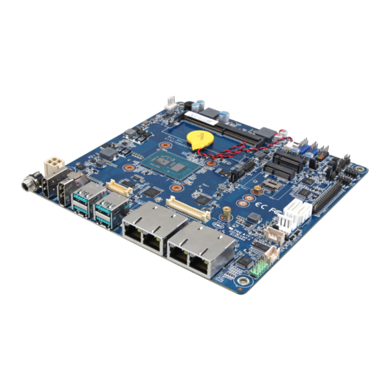
Page 17: Product Overview
User’s Manual 2.1 Product Overview EMX-EHLP User’s Manual 17... -
Page 18: Jumper And Connector List
3 x 1 header, pitch 2.00mm JM2BP1 M2KB1 Voltage setting 3 x 1 header, pitch 2.00mm Connectors Label Function Note JFP1 Miscellaneous setting connector 1 5 x 2 header, pitch 2.54mm JDIMM1 260-pin DDR4 SO-DIMM socket 18 EMX-EHLP User’s Manual... - Page 19 SATA Power connector 1/2 JSIM1 JSIM connector JSIM2 JSIM connector 10 x 1 header, pitch 0.50mm 4 x 1 wafer, pitch 2.54mm JFAN1 CPU fan connector JHDMI1 HDMI connector DP connector 1 JDP1 RJ-45 Ethernet 1/2 JLAN1/2 EMX-EHLP User’s Manual 19...
-
Page 20: Setting Jumpers & Connectors
EMX-EHLP User’s Manual 2.3 Setting Jumpers & Connectors 2.3.1 Serial port 1/2 pin9 signal select (JRI-1/JRI-2) Ring* JRI1 JRI2 +12V * Default 2.3.2 Clear CMOS (JCMOS1) Protect* Clear CMOS * Default 20 EMX-EHLP User’s Manual... -
Page 21: M2Kb1 Voltage Setting (Jm2Bp1)
User’s Manual 2.3.3 M2KB1 Voltage setting (JM2BP1) +3.3V* +3.8V * Default 2.3.4 Backlight for PWM or DC select (JBLS1) PWM* * Default EMX-EHLP User’s Manual 21... -
Page 22: Backlight Power For +V3.3 Or +V5 Select (Jblp1)
EMX-EHLP User’s Manual 2.3.5 Backlight power for +V3.3 or +V5 select (JBLP1) +3.3V* * Default 2.3.6 Panel Power (JEDP_LVDS1) +3.3V* * Default 22 EMX-EHLP User’s Manual... -
Page 23: At/Atx Power Mode Select (Jat1)
User’s Manual 2.3.7 AT/ATX Power Mode Select (JAT1) * Default 2.3.8 LCD Inverter connector (JBL1) Signal +V12S_INV BKLEN VBRIGHT +V5S_INV EMX-EHLP User’s Manual 23... -
Page 24: Edp_Panel Connector (Jedp1)
2.3.9 eDP_Panel connector (JEDP1) Signal Signal JEDP1_TXN0 JEDP1_TXN3 JEDP1_TXP0 JEDP1_TXP3 JEDP1__TXN1 JEDP1__TXP1 JEDP1_AUXN JEDP1_AUXP JEDP1__TXN2 JEDP1__TXP2 JEDP1_HPD +V12_JEDP1 +V12_JEDP1 2.3.10 Serial port1 connector (JCOM1) Signal PIN PIN Signal COM_DCD#1 COM_RXD1 COM_TXD1 COM_DTR#1 COM_DSR#1 COM_RTS#1 COM_CTS#1 COM_PIN9_1 24 EMX-EHLP User’s Manual... -
Page 25: Serial Port2 Connector (Jcom2)
User’s Manual 2.3.11 Serial port2 connector (JCOM2) Signal PIN PIN Signal COM_DCD#2 COM_RXD2 COM_TXD2 COM_DTR#2 COM_DSR#2 COM_RTS#2 COM_CTS#2 COM_PIN9_2 2.3.12 Battery connector (JBAT1) Signal +V3.3A_EC EMX-EHLP User’s Manual 25... -
Page 26: Serial Port 1 Rs485/422 Mode Connector (J485-1)
EMX-EHLP User’s Manual 2.3.13 Serial Port 1 RS485/422 Mode connector (J485-1) Signal PIN PIN Signal 485TX-_2 485TX+_2 422RX+_2 422RX-_2 2.3.14 Serial Port 2 RS485/422 Mode connector (J485-2) Signal PIN PIN Signal 485TX-_2 485TX+_2 422RX+_2 422RX-_2 26 EMX-EHLP User’s Manual... -
Page 27: General Purpose I/O Connector (Jdio1)
General purpose I/O connector (JDIO1) Signal PIN PIN Signal DIO_GP20 DIO_GP10 DIO_GP21 DIO_GP11 DIO_GP22 DIO_GP12 DIO_GP23 DIO_GP13 DIO_GP24 DIO_GP14 DIO_GP25 DIO_GP15 DIO_GP26 DIO_GP16 DIO_GP27 DIO_GP17 SMB_CLK_5V SMB_DATA_5V +V5S_DIO (Max current = 0.5A) 2.3.16 Power connector (JPWR3) Signal Signal +V24_DCIN +V24_DCIN EMX-EHLP User’s Manual 27... -
Page 28: Sata Power Connector 1 (Jsatap1)
EMX-EHLP User’s Manual 2.3.17 SATA Power connector 1 (JSATAP1) Signal +V5_JSATA1 +V12_JSATA1 2.3.18 SATA Power connector 2 (JSATAP2) Signal +V5_JSATA2 +V12_JSATA2 28 EMX-EHLP User’s Manual... -
Page 29: Usb Connector 3 (Jusb3)
User’s Manual 2.3.19 USB connector 3 (JUSB3) Signal Signal JUSB3-2_USB6P JUSB3-1_USB5P JUSB3-2_USB6N JUSB3-1_USB5N +V5+JUSB3 +V5+JUSB3 2.3.20 USB connector 4 (JUSB4) Signal Signal JUSB4-2_USB8P JUSB4-1_USB7P JUSB4-2_USB8N JUSB4-1_USB7N +V5+JUSB4 +V5+JUSB4 EMX-EHLP User’s Manual 29... -
Page 30: Speaker Connector (Jspk1)
EMX-EHLP User’s Manual 2.3.21 Speaker connector (JSPK1) Signal LSPK+ LSPK- RSPK+ RSPK- 2.3.22 SPI connector (JSPI1) Signal PIN PIN Signal CN_ESPI_IO0 +3.3V CN_ESPI_IO1 PLT_RST_BUF# CN_ESPI_IO2 CPU_ESPI_CS#0 CN_ESPI_IO3 CN_ESPI_CLK CPU_ESPI_RST# 11 CPU_ESPI_ALERT#0 30 EMX-EHLP User’s Manual... -
Page 31: Audio Connector (Jfaud1)
User’s Manual 2.3.23 Audio connector (JFAUD1) Signal PIN PIN Signal MIC2_LIN MIC2_RIN ACZ_DET#_FRONT LINE2_LIN MIC2_JD LINE2_LIN LINE2_JD 2.3.24 Miscellaneous setting connector 1 (JFP1) Signal PIN PIN Signal PMC_RSTBTN# EC_PWR_BTN_IN# SYS_RESET# PWR_LED# HDD_LED- PWR_LED+ HDD_LED+ EMX-EHLP User’s Manual 31... -
Page 32: Cpu Fan Connector (Jfan1)
EMX-EHLP User’s Manual 2.3.25 CPU fan connector (JFAN1) Signal +12V EC_CFAN_IN_TECH EC_CFAN_OUT_PWM 2.3.26 JSIM connector (JSIM2) Signal +VCC_UIM M2B_UIM_RESET# VPP_JSIM2 M2B_UIM_CLK M2B_UIM_DATA SIM_DET1 SIM_DET2 32 EMX-EHLP User’s Manual... -
Page 33: Jbios Connector (Jbios)
User’s Manual 2.3.27 JBIOS connector (JBIOS) Signal PIN PIN Signal + V3.3A_SPI SPI_CS#0 SPI_CLK SPI_MISO SPI_MOSI SPI_HOLD# SPI_WP# 2.3.28 JLAN_LED connector (JLAN_LED1) Signal PIN PIN Signal I225-2_LED_ACT_N I225-2_LED_ACT_P I225-B_LED_ACT_N I225-B_LED_ACT_P I225-1_LED_ACT_N I225-1_LED_ACT_P I225-A_LED_ACT_N I225-A_LED_ACT_P EMX-EHLP User’s Manual 33... -
Page 34: Serial Port 3 Connector (Jcom3_1)
Signal PIN PIN Signal COM_RI#6 COM_CTS#6 COM_RTS#6 COM_DSR#6 COM_DTR#6 COM_TXD6 COM_RXD6 COM_DCD#6 COM_RI#5 COM_CTS#5 COM_RTS#5 COM_DSR#5 COM_DTR#5 COM_TXD5 COM_RXD5 COM_DCD#5 COM_RI#4 COM_CTS#4 COM_RTS#4 COM_DSR#4 COM_DTR#4 COM_TXD4 COM_RXD4 COM_DCD#4 COM_RI#3 COM_CTS#3 COM_RTS#3 COM_DSR#3 COM_DTR#3 COM_TXD3 COM_RXD3 COM_DCD#3 34 EMX-EHLP User’s Manual... -
Page 35: Jlvds Connector (Jlvds1)
LVDS_DATA0_N 12 11 LVDS_DATA1_N LVDS_DATA2_P 16 15 LVDS_DATA3_P LVDS_DATA2_N 18 17 LVDS_DATA3_N LVDS_DATA4_P 22 21 LVDS_DATA5_P LVDS_DATA4_N 24 23 LVDS_DATA5_N LVDS_DATA6_P 28 27 LVDS_DATA7_P LVDS_DATA6_N 30 29 LVDS_DATA7_N LVDS_CLK1_P LVDS_CLK2_P LVDS_ CLK1_N LVDS_ CLK2_N +V12_LVDS +V12S_LVDS EMX-EHLP User’s Manual 35... -
Page 36: Bios Setup
EMX-EHLP User’s Manual 3.BIOS Setup 36 EMX-EHLP User’s Manual... -
Page 37: Introduction
If you do not press the keys at the correct time and the system does not boot, an error message will be displayed and you will again be asked to. Press F1 to Continue, DEL to enter SETUP EMX-EHLP User’s Manual 37... -
Page 38: Using Setup
Note: Some of the navigation keys differ from one screen to another. To Display a Sub Menu Use the arrow keys to move the cursor to the sub menu you want. Then press <Enter>. A “” pointer marks all sub menus. 38 EMX-EHLP User’s Manual... -
Page 39: Getting Help
BIOS Vendor and your systems manufacturer to provide the absolute maximum performance and reliability. Even a seemingly small change to the chipset setup has the potential for causing you to use the override. EMX-EHLP User’s Manual 39... -
Page 40: Bios Setup
<Enter> to accept and enter the sub-menu. 3.6.1 Main Menu This section allows you to record some basic hardware configurations in your computer and set the system clock. 40 EMX-EHLP User’s Manual... -
Page 41: System Language
Visit the Avalue website (www.avalue.com.tw) to download the latest product and BIOS information. 3.6.2 Advanced Menu This section allows you to configure your CPU and other system devices for basic operation through the following sub-menus. EMX-EHLP User’s Manual 41... -
Page 42: Cpu Configuration
Disabled When enabled, a VMM can utilize the additional hardware Virtualization Enabled[Default], capabilities provided by Vanderpool Technology. Technology Active Processor All[Default], Number of cores to enable in each processor package. Cores 1/2/3 3.6.2.2 Power & Performance 42 EMX-EHLP User’s Manual... -
Page 43: Cpu - Power Management Control
P-states. Enable/Disable processor Turbo Mode (requires Disabled Turbo Mode Enabled[Default], EMTTM enabled too). AUTO means enabled. Disabled[Default], Enable/Disable C1E. When enabled, CPU will switch C-states Enabled to minimum speed when all cores enter C-State. EMX-EHLP User’s Manual 43... -
Page 44: View/Configure Turbo Options
Enable/Disable Energy Efficient Turbo Feature. This feature will opportunistically lower the turbo frequency to increase Energy Efficient Disabled efficiency. Recommended only to disable in overclocking Turbo Enabled[Default], situations where turbo frequency must remain constant. Otherwise, leave enabled. 44 EMX-EHLP User’s Manual... -
Page 45: Gt - Power Management Control
Check to enable render standby. (Render Standby) Enabled[Default], Default Max Frequency[Default], 100Mhz/150Mhz/200Mhz/250Mhz/ 300Mhz/350Mhz/400Mhz/450Mhz/ Maximum GT 500Mhz/550Mhz/600Mhz/650Mhz/ Auto Updated frequency 700Mhz/750Mhz/800Mhz/850Mhz/ 900Mhz/950Mhz/1000Mhz/1050Mhz/ 1100Mhz/1150Mhz/1200Mhz Disable Turbo GT Disabled[Default], Enabled: Disables Turbo GT frequency is not frequency Enabled limited EMX-EHLP User’s Manual 45... -
Page 46: Pch-Fw Configuration
EMX-EHLP User’s Manual 3.6.2.3 PCH-FW Configuration 3.6.2.3.1 Firmware Update Configuration Item Options Description Disabled[Default], Me FW Image Re-Flash Enable/Disable Me FW Image Re-Flash function. Enabled 46 EMX-EHLP User’s Manual... -
Page 47: Ptt Configuration
3.6.2.4 Trusted Computing Item Options Description Enables or Disables BIOS support for security device. O.S. Security Device Disabled will not show Security Device. TCG EFI protocol and Support Enabled[Default], INT1A interface will not be available. EMX-EHLP User’s Manual 47... -
Page 48: Acpi Settings
S3 (Suspend to RAM)[Default] pressed. 3.6.2.6 IT5571 Super IO Configuration You can use this item to set up or change the IT8528 Super IO configuration for serial ports. Please refer to 3.6.2.5.1~ 3.6.2.5.6 for more information. 48 EMX-EHLP User’s Manual... -
Page 49: Serial Port 1 Configuration
Serial Port 4 Configuration Set Parameters of Serial Port 4 (COMD). Serial Port 5 Configuration Set Parameters of Serial Port 5 (COME). Serial Port 6 Configuration Set Parameters of Serial Port 6 (COMF). 3.6.2.6.1 Serial Port 1 Configuration EMX-EHLP User’s Manual 49... -
Page 50: Serial Port 2 Configuration
UART 485 3.6.2.6.2 Serial Port 2 Configuration Item Option Description Disabled Serial Port Enable or Disable Serial Port (COM). Enabled[Default], UART 232[Default], UART 232 422 485 UART 422, Change the Serial Port as RS232/422/485. UART 485 50 EMX-EHLP User’s Manual... -
Page 51: Serial Port 3 Configuration
3.6.2.6.3 Serial Port 3 Configuration Item Option Description Disabled Serial Port Enable or Disable Serial Port (COM). Enabled[Default], 3.6.2.6.4 Serial Port 4 Configuration Item Option Description Disabled Serial Port Enable or Disable Serial Port (COM). Enabled[Default], EMX-EHLP User’s Manual 51... -
Page 52: Serial Port 5 Configuration
3.6.2.6.5 Serial Port 5 Configuration Item Option Description Disabled Serial Port Enable or Disable Serial Port (COM). Enabled[Default], 3.6.2.6.6 Serial Port 6 Configuration Item Option Description Disabled Serial Port Enable or Disable Serial Port (COM). Enabled[Default], 52 EMX-EHLP User’s Manual... -
Page 53: Ec 8528 H/W Monitor
Enable or disable System wake on alarm event. Select Disabled[Default], FixedTime, system will wake on the hr::min::sec specified. Wake system from S5 Fixed Time Select DynamicTime, System will wake on the current time Dynamic Time + Increase minutes(s). EMX-EHLP User’s Manual 53... -
Page 54: Serial Port Console Redirection
Item Option Description Disabled[Default], Console Redirection Console Redirection Enable or Disable. Enabled Console Redirection Disabled[Default], Console Redirection Enable or Disable. Enabled 3.6.2.10 USB Configuration The USB Configuration menu helps read USB information and configures USB settings. 54 EMX-EHLP User’s Manual... -
Page 55: Network Stack Configuration
Forced FDD emulated as ‘CDROM’, drives with no media will be Devices Hard Disk emulated according to a drive type. CD-ROM 3.6.2.11 Network Stack Configuration Item Option Description Disabled[Default] Network Stack Enable/Disable UEFI Network Stack. Enabled EMX-EHLP User’s Manual 55... -
Page 56: Chipset
3.6.3.1 System Agent (SA) Configuration Item Option Description Disabled VT-d VT-d capability. Enabled[Default] Enable/Disable above 4GB MemoryMappedIO BIOS Above 4GB MMIO Enabled[Default], assignment This is enabled automatically when Aperture Disabled BIOS assignment Size is set to 2048MB. 56 EMX-EHLP User’s Manual... -
Page 57: Memory Configuration
In-Band ECC Error allows attackers who have access to the Enabled Disabled[Default], Injection Host Operating System to inject IBECC errors that can cause unintended memory corruption and enable the leak of security data in the BlOS stolen EMX-EHLP User’s Manual 57... -
Page 58: Graphics Configuration
Select the GTT Size 8MB[Default] 128MB Select the Aperture Size Note : Above 4GB MMIO BIOS 256MB[Default] assignment is automatically enabled when selecting Aperture Size 512MB 2048MB aperture. To use this feature, please disable CSM 1024MB Support. 58 EMX-EHLP User’s Manual... -
Page 59: Pch-Io Configuration
User’s Manual 3.6.3.2 PCH-IO Configuration 3.6.3.2.1 PCI Express Configuration EMX-EHLP User’s Manual 59... -
Page 60: Pci Express Root Port 2(Lan1-I225/I226)
State AUTO – BIOS auto configure DISABLE – Disables ASPM L0sL1 ASPM. Auto Disabled[Default] L1 Substates L1.1 PCI Express L1 Substates settings. L1.1 & L1.2, Disabled[Default], Enable/Disable Precision Time Measurement. Enabled Auto Gen1 PCIe Speed Select PCIe speed. Gen2 Gen3[Default] 60 EMX-EHLP User’s Manual... -
Page 61: Pci Express Root Port 3(Lan2-I225/I226)
State AUTO – BIOS auto configure DISABLE – Disables ASPM L0sL1 ASPM. Auto Disabled[Default], L1 Substates L1.1 PCI Express L1 Substates settings. L1.1 & L1.2 Disabled[Default], Enable/Disable Precision Time Measurement. Enabled Auto Gen1 PCIe Speed Select PCIe speed. Gen2 Gen3[Default] EMX-EHLP User’s Manual 61... -
Page 62: Pci Express Root Port 4(Lan3-I225/I226)
State AUTO – BIOS auto configure DISABLE – Disables ASPM L0sL1 ASPM. Auto Disabled[Default], L1 Substates L1.1 PCI Express L1 Substates settings. L1.1 & L1.2 Disabled[Default], Enable/Disable Precision Time Measurement. Enabled Auto Gen1 PCIe Speed Select PCIe speed. Gen2 Gen3[Default], 62 EMX-EHLP User’s Manual... -
Page 63: Pci Express Root Port 5(Lan4-I225/I226)
State AUTO – BIOS auto configure DISABLE – Disables ASPM L0sL1 ASPM. Auto Disabled[Default], L1 Substates L1.1 PCI Express L1 Substates settings. L1.1 & L1.2 Disabled[Default], Enable/Disable Precision Time Measurement. Enabled Auto Gen1 PCIe Speed Select PCIe speed. Gen2 Gen3[Default] EMX-EHLP User’s Manual 63... -
Page 64: Pci Express Root Port 7(M.2 Keye)
State AUTO – BIOS auto configure DISABLE – Disables ASPM L0sL1 ASPM. Auto Disabled[Default], L1 Substates L1.1 PCI Express L1 Substates settings. L1.1 & L1.2 Disabled[Default], Enable/Disable Precision Time Measurement. Enabled Auto[Default] Gen1 PCIe Speed Select PCIe speed. Gen2 Gen3 64 EMX-EHLP User’s Manual... -
Page 65: Sata And Rst Configuration
Otherwise all drives spin up at boot. Hard Disk Drive Identify the SATA port is connected to Solid State Drive SATA Device Type Solid State Drive[Default], or Hard Disk Drive EMX-EHLP User’s Manual 65... -
Page 66: Usb Configuration
3.6.3.2.3 USB Configuration Item Option Description Option to enable Compliance Mode. Default is to disable Disabled[Default], XHCI Compliance Mode Compliance Mode. Change to enabled for Compliance Enabled Mode testing. 3.6.3.2.4 HD Audio Configuration 66 EMX-EHLP User’s Manual... -
Page 67: Board & Panel Configuration
1600 x1200 24/2 1366 x768 24/1 1920 x1080 24/2 1680 x1050 24/2 Panel Brightness BIOS[Default] Panel Brightness Control Method. 1.BIOS 2. Control Method OS Driver Brightness Button Panel Back Light Select Panel back light PWM duty. 100%[Default] EMX-EHLP User’s Manual 67... -
Page 68: Security
Enabled/Disabled JUSB3, JUSB4 Standby Power Power(Internal) Enabled[Default], during S3/S4/S5 AMP GAIN 32DB Select AMP GAIN. Disabled[Default], SHOW DMI INFO SHOW DMI INFO Enabled 3.6.4 Security Administrator Password Set setup Administrator Password User Password Set User Password 68 EMX-EHLP User’s Manual... -
Page 69: Secure Boot Menu
Secure Boot mode options: Standard or Custom. In Standard[Default] Custom mode, Secure Boot Policy variables can be Secure Boot Mode Custom configured by a physically present user without full authentication 3.6.4.1.1 Restore Factory Keysestore Factory Keys EMX-EHLP User’s Manual 69... -
Page 70: Key Management
System is in Setup mode 3.6.5 Security Item Option Description Setup Prompt Number of seconds to wait for setup activation key. Timeout 65535(0xFFFF) means indefinite waiting. Bootup NumLock On[Default] Select the Keyboard NumLock state State 70 EMX-EHLP User’s Manual... -
Page 71: Save And Exit
Enables or disables Quiet Boot option Enabled Boot Option #1 Set the system boot order. Boot Option #2 Set the system boot order. 3.6.6 Save and exit 3.6.6.1 Save Changes and Reset Reset the system after saving the changes. EMX-EHLP User’s Manual 71... -
Page 72: Discard Changes And Reset
Reset system setup without saving any changes. 3.6.6.3 Restore Defaults Restore/Load Default values for all the setup options. 3.6.6.4 Launch EFI Shell from filesystem device Attempts to Launch EFI Shell application (Shell.efi) from one of the available filesystem devices. 72 EMX-EHLP User’s Manual... -
Page 73: Drivers Installation
User’s Manual 4. Drivers Installation Note: Installation procedures and screen shots in this section are for your reference and may not be exactly the same as shown on your screen. EMX-EHLP User’s Manual 73... -
Page 74: Install Chipset Driver
All drivers can be found on the Avalue Official Website: http://www.avalue.com.tw. Note: The installation procedures and screen shots in this section are based on Windows 10 operation system. Step 3. Click Install. Step1. Click Next. Step 2. Click Accept. Step 4. Setup completed. 74 EMX-EHLP User’s Manual... -
Page 75: Install Vga Driver
Note: The installation procedures and screen shots in this section are based on Windows 10 operation system. Step 1. Click Begin installation. Step 3. Click Start. Step 4. Click Finish to complete setup. Step 2. Click Next. EMX-EHLP User’s Manual 75... -
Page 76: Install Ethernet Driver
Windows 10 operation system. Step 3. Click Next. Step 1. Click Install Drivers and Software to continue installation. Step 4. Click Next. Step 2. Click Next. Step 5. Click Install. 76 EMX-EHLP User’s Manual... - Page 77 User’s Manual Step 6. Click Finish to complete setup. EMX-EHLP User’s Manual 77...
-
Page 78: Install Display Audio Driver
Windows 10 operation system. Step 3. Click Next. Step 1. Click Update Drivers. Step 4. Click Next. Step 2. Click Browse my computer for Step 5. Click OK. drivers. 78 EMX-EHLP User’s Manual... - Page 79 User’s Manual Step 6. Click Next. Step 7. Click Yes. Step 8. Install complete. EMX-EHLP User’s Manual 79...
-
Page 80: Install Me Driver
Continue to go on. Step 3. Click Next to continue installation. Step1. Click Next to start installation. Step 4. Installing. Step 2. Click Next. Step 5. Click Finish to complete setup. 80 EMX-EHLP User’s Manual... -
Page 81: Mechanical Drawing
User’s Manual 5. Mechanical Drawing EMX-EHLP User’s Manual 81... - Page 82 EMX-EHLP User’s Manual Unit: mm 82 EMX-EHLP User’s Manual...
- Page 83 User’s Manual Unit: mm EMX-EHLP User’s Manual 83...
Need help?
Do you have a question about the EMX-EHLP and is the answer not in the manual?
Questions and answers