Table of Contents
Advertisement
Advertisement
Table of Contents

Related Manuals for Hangar 9 Christen Eagle II 90 ARF


Summary of Contents for Hangar 9 Christen Eagle II 90 ARF
- Page 1 Christen Eagle II 90 ARF Assembly Manual...
-
Page 2: Table Of Contents
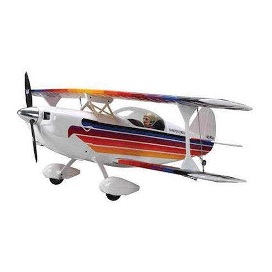
The following terms are used throughout the product UltraCote Covering Colors ..........5 The Hangar 9 Christen Eagle II 90 ARF brilliantly captures the literature to indicate various levels of potential harm Recommended Power Setups ...........5 spirit of this remarkable airplane. -
Page 3: Included Parts Listing
Cabane strut attachment to center rib 1 .... 12mm x 370mm aluminum tube Upper wing joiner 1 .... 12mm x 420mm aluminum tube Lower wing joiner 1 .... 1.5mm x 750mm rod with nylon housing Throttle pushrod Hangar 9 Christen Eagle II 90 ARF... -
Page 4: Contents Of Kit And Parts Listing
10. HAN501013 Fiberglass Wheel Pants 11. HAN501014 Wheels and Tailwheel Assembly SMALL PARTS This kit includes small parts and should not be left unattended near children as choking and serious injury could result. Hangar 9 Christen Eagle II 90 ARF... -
Page 5: Important Information Regarding Warranty
Deep Blue HANU873 operate all the functions of your aircraft. We suggest the • B e aware of any other radio frequency user who may Orange HANU877 following radio systems available through Horizon Hobby or present an interference problem. Black HANU874 your local hobby distributor. Smoke Purple HANU868 •... -
Page 6: Field Equipment Required
Scissors Wing tube size Side cutters Upper: 12mm x 371mm Spray bottle Lower: 12mm x 425mm Square Straight edge Tie wraps Toothpicks T-pins Two-sided tape Hangar 9 Christen Eagle II 90 ARF... -
Page 7: Landing Gear Installation
Use the M4 x 20 socket head screws and a 3mm hex wrench to secure the landing gear to the fuselage. Use threadlock on the screws to prevent them from vibrating loose. Hangar 9 Christen Eagle II 90 ARF... - Page 8 10. Place the 5/16-inch metal washer, then the 5/16- inch plywood washer on the threaded portion of the axle. Fit the assembly into the wheel pant. You may need to flex the wheel pant open slightly to fit the axle in. Hangar 9 Christen Eagle II 90 ARF...
-
Page 9: Tail Installation
Use low-tack tape to keep the joiner wire in position until the epoxy fully cures. Use a straight edge along the hinge line to keep the elevators aligned while the epoxy cures. Hangar 9 Christen Eagle II 90 ARF... - Page 10 Note that the holes for mounting the control horn are on the right side of the fuselage when viewed from the top. Check Alignment Hangar 9 Christen Eagle II 90 ARF...
- Page 11 Avoid cutting into the underlying wood, which Avoid cutting into the underlying wood, which could weaken the structure of your model. could weaken the structure of your model. Hangar 9 Christen Eagle II 90 ARF...
-
Page 12: Tail Wheel And Control Horn Installation
It may be necessary to use a pin vise and 5/64-inch (2mm) drill bit to clear the holes if any of the hinges are blocking the mounting holes. Hangar 9 Christen Eagle II 90 ARF... -
Page 13: Radio Installation
Use the screws provided with the servos to secure them in the fuselage. Make sure the servo output shaft faces the front of the fuselage for both servos. Use a #1 Phillips screwdriver to tighten the screws. Hangar 9 Christen Eagle II 90 ARF... - Page 14 Apply threadlock to the nut and clevis to prevent them from vibrating loose. Use pliers to tighten the nut against the clevis to prevent it from vibrating and changing position. Hangar 9 Christen Eagle II 90 ARF...
-
Page 15: Aileron Servo Installation
2. Hinge the aileron following the procedure found in the section “Tail Installation.” Fit the aileron to the wing. Before gluing the hinges, make sure the ends of the aileron are spaced evenly in the opening. Hangar 9 Christen Eagle II 90 ARF... - Page 16 Use the string to pull the extension and servo lead through the wing. Secure the aileron servo and cover to the wing using the M2 x 12 self-tapping screws removed in step 3 and a #1 Phillips screwdriver. Hangar 9 Christen Eagle II 90 ARF...
-
Page 17: Cabane Strut Installation
We recommend using a open accidentally in flight. trim seal tool to iron the covering neatly into the openings in the fuselage. Hangar 9 Christen Eagle II 90 ARF... -
Page 18: Electric Power Installation
1/16-inch (1.5mm) drill bit to drill the four pilot fasteners to prevent them from vibrating loose. holes for the wood box mounting screws. 2. Place the two hook and loop straps on the wood tray. Hangar 9 Christen Eagle II 90 ARF... - Page 19 Connect the batteries to the speed control using a Y-harness. Once the motor and batteries have been installed, skip to the section “Cowling Installation,” as the following sections cover the installation of a glow engine and its related components. Hangar 9 Christen Eagle II 90 ARF...
-
Page 20: 4-Stroke Engine Installation
Use a drill and 1/16-inch (1.5mm) drill bit to drill the four pilot holes for the wood box mounting screws. Hangar 9 Christen Eagle II 90 ARF... -
Page 21: Fuel Tank Installation
(fill tube). Use a tubing bender to avoid kinking the tubing while bending. We recommend removing the mounts from the firewall and using a drill press to drill the holes for best results. Hangar 9 Christen Eagle II 90 ARF... - Page 22 Once set, use a #1 Phillips screwdriver to tighten the screw to secure the stopper. Do not over-tighten the stopper and distort or split the neck of the tank. Add fuel tubing to reach bottom Hangar 9 Christen Eagle II 90 ARF...
-
Page 23: Throttle Pushrod Installation
The next two are 5 inches (140mm) and 9 inches (324mm) from the end as shown. This will allow the CA to adhere to the pushrod when it is glued into position. Hangar 9 Christen Eagle II 90 ARF... -
Page 24: Cowling Installation
Make sure to leave enough wire to ensure the linkage can be connected properly. It may be necessary to remove the needle valve when a glow engine has been installed. Hangar 9 Christen Eagle II 90 ARF... - Page 25 EP option, skip to Step 13. It may be necessary to cut an opening in the cowl to clear the head of the engine or valve covers, depending on your choice of engines. Hangar 9 Christen Eagle II 90 ARF...
- Page 26 Hangar 9 Christen Eagle II 90 ARF...
-
Page 27: Wing Installation
2. Insert two 2.6mm x 16mm aluminum pins in the bottom of the interplane strut. Use a very small amount of medium CA to secure the pins. Make sure the CA has fully cured before proceeding. Hangar 9 Christen Eagle II 90 ARF... - Page 28 When installing the top wing, the pins will be in position in the interplane struts. Use care not to damage the covering on the bottom of the top wing during installation. Hangar 9 Christen Eagle II 90 ARF...
-
Page 29: Center Of Gravity
14. Repeat Steps 12 and 13 to remove the remaining wing panels from the fuselage. To reattach the wings, simply perform Steps 12 through 14 in reverse order. Hangar 9 Christen Eagle II 90 ARF... -
Page 30: Control Throws
Use caution if experimenting with CG positions rearward of the recommended range. Down: 1 inches 25 mm Rudder: High Rate: Right: inches 47 mm Left: inches 47 mm Low Rate: Right: inches 35 mm Left: inches 35 mm Hangar 9 Christen Eagle II 90 ARF... -
Page 31: Preflight
• D o not take chances. If at any time during flight systems. Next, run the motor. With the model securely service by anyone other than a Horizon Hobby authorized you observe any erratic or abnormal operation, land anchored, check the range again. The range test should not service center, or (v) Products not purchased from an immediately and do not resume flight until the cause of be significantly affected. -
Page 32: Warranty Services
Notice: Do not ship LiPo batteries to horizon. If you have any issue with a LiPo 4105 Fieldstone Rd battery, please contact the appropriate Champaign, Illinois horizon Product Support office. 61822 USA productsupport@horizonhobby.com 877-504-0233 Hangar 9 Christen Eagle II 90 ARF... -
Page 33: Compliance Information For The European Union
5. RC model aircraft will not operate within three (3) miles of any pre-existing flying site without a frequency-management • F ree Flight fuses or devices that burn producing smoke and are agreement (AMA Documents #922- Testing for RF Interference; securely attached to the model aircraft during flight. #923- Frequency Management Agreement) Hangar 9 Christen Eagle II 90 ARF... -
Page 34: Building And Flying Notes
50 feet to any above- ground electric utility lines. 5. The flying area must be clear of all nonessential participants and spectators before the engine is started. Hangar 9 Christen Eagle II 90 ARF... -
Page 35: Building And Flying Notes
Building and Flying Notes Hangar 9 Christen Eagle II 90 ARF... - Page 36 Hangar9.com Hangar 9, Evolution, JR, DSM2, DSMX, PowerPro, EC3, UltraCote and the Horizon Hobby logo are trademarks or registered trademarks of Horizon Hobby, Inc. The Spektrum trademark is used with permission of Bachmann Industries, Inc. Saito is a trademark of Saito Seisakusho Co. Ltd, Japan.
Need help?
Do you have a question about the Christen Eagle II 90 ARF and is the answer not in the manual?
Questions and answers