Table of Contents
Advertisement
Quick Links
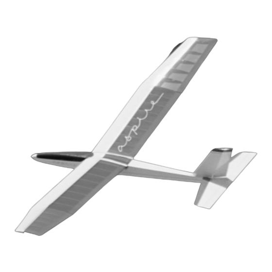
WE GET PEOPLE FLYING
INSTRUCTION MANUAL
• 90% pre-built
• Pre-covered in Goldberg UltraCote
• Includes sailplane hardware package with adjustable tow hook
• Superb stability during "Hi-Start" launches
Specifications:
Wingspan: . . . . . . . . . . . . . . . . . . . . . . . . . . . . . . . . . . . . . 79"
Length: . . . . . . . . . . . . . . . . . . . . . . . . . . . . . . . . . . . . . . 45"
Wing Area:. . . . . . . . . . . . . . . . . . . . . . . . . . . . . . . . 680 sq. in
Weight (Approx.): . . . . . . . . . . . . . . . . . . . . . . . . . 36–48 oz.
TM
TM
®
transparent blue and white covering
2 meters
114 cm
4387 sq cm
1020–1360g
Advertisement
Table of Contents

Subscribe to Our Youtube Channel
Related Manuals for Hangar 9 ULTRA aspire


Summary of Contents for Hangar 9 ULTRA aspire
- Page 1 WE GET PEOPLE FLYING INSTRUCTION MANUAL • 90% pre-built • Pre-covered in Goldberg UltraCote ® transparent blue and white covering • Includes sailplane hardware package with adjustable tow hook • Superb stability during “Hi-Start” launches Specifications: Wingspan: ........79" 2 meters Length: .
-
Page 2: Table Of Contents
Section 14: Hangar 9 G-Force ........ -
Page 3: Introduction
Horizon Hobby Distributors 4105 Fieldstone Road Champaign, IL 61822 217-355-9511 Visit our web site at www.horizonhobby.com Thank you again for purchasing the Hangar 9 Aspire sailplane. We believe you will have many enjoyable hours of challenging and rewarding flight. -
Page 4: Additional Equipment Required
Additional Equipment Required Radio Equipment 2 channels (minimum) 2 standard servos You will need at least a two channel radio control system with two servos on an aircraft frequency for use in your Aspire. A standard radio system (4 channels with standard servos) will work fine. The standard size servos will fit into the fuselage of the Aspire. Recommended JR Systems JR F400EX Field Equipment... -
Page 5: Optional Field Equipment
Optional Field Equipment Weight for balancing your Aspire: You will need to balance your Aspire after you’ve completed assembly and have installed the receiver, battery and servos. Use of the stick-on type of weights is recommended and can be obtained at your dealer. Before adding weight to the sailplane, try moving the receiver battery pack to adjust the center of gravity (usually as far forward as possible). - Page 6 Kit Contents Note: Photo of product may vary slightly from contents in box. 1. Left wing – HAN1427 2. Right wing – HAN1427 3. Vertical stabilizer/rudder – HAN1428 Main Parts Other Parts A. #64 rubber bands H. Nylon adjustable tow hook – O.
-
Page 7: Section 1: Joining The Wing
Section 1: Joining the Wing Parts Needed Tools and Adhesives Needed • Right wing panel • 30-minute epoxy • Ruler • Left wing panel • Rubbing alcohol • Pencil or felt tipped pen • Hardwood wing joiner (dihedral brace) • Paper towels •... - Page 8 Section 1: Joining the Wing CONTINUED Step 6. Place one wing half on a flat surface (remember the Note: You will need to mix up an additional ounce or so of wax paper under the wing). Use an epoxy brush to smear a epoxy to complete the wing joining process.
- Page 9 Section 1: Joining the Wing CONTINUED Step 10. Carefully slide the two wing halves together and firmly press them together, allowing the excess epoxy to run out. Also, check to make sure the wing halves align properly. Wipe any excess epoxy away with rubbing alcohol and paper towels. Step 11.
-
Page 10: Section 2: Mounting The Wing
Section 2: Mounting the Wing Parts Needed Tools and Adhesives Needed • Complete wing assembly • Hobby knife • Rubbing alcohol • Wing dowel rods (2) • 6-minute epoxy • Felt tip pen or pencil • Fuselage • Paper towels •... -
Page 11: Section 3: Installing The Tail
Section 3: Installing the Tail Parts Needed Tools and Adhesives Needed • Fuselage • Hobby knife • Rubbing alcohol • Horizontal stabilizer with elevator • Ruler • Paper towels • Vertical stabilizer with rudder • Felt tipped pen • Epoxy brush •... - Page 12 Section 3: Installing the Tail CONTINUED Step 6. Remove the horizontal stabilizer and use a sharp Step 8. When you’re satisfied with the alignment, use a hobby knife to carefully cut away the covering approximately pencil to mark the junction of the vertical stabilizer and fuselage 1/16”...
- Page 13 Section 3: Installing the Tail CONTINUED Step 10. With the fuselage resting on a flat surface and the horizontal stabilizer attached to the fuselage, adjust the stabilizer until you have an equal distance on both the right and left sides of the stabilizer to the wing.
-
Page 14: Section 4: Hinging The Rudder And Elevator
Section 4: Hinging the Rudder and Elevator Parts Needed Tools and Adhesives Needed • Fuselage • Thin CA glue • Drill • Horizontal stabilizer with elevator attached • CA debonder • Drill bit: ” • Vertical stabilizer with rudder attached •... - Page 15 Section 4: Hinging the Rudder and Elevator CONTINUED Step 5. Use CA remover/debonder and a paper towel to Step 8. You will next attach the rudder and elevator control remove excess CA from the elevator and horizontal stabilizer. horns. Locate the nylon control horns (2), backplates (2) and the four 8mm long control horn screws.
- Page 16 Section 4: Hinging the Rudder and Elevator CONTINUED Step 11. Remove the horn and using a ” drill bit, drill the Step 14. Attach the elevator and rudder control horns using holes for the elevator control horn screws in the elevator. the four 8mm screws and a medium Phillips screwdriver.
-
Page 17: Section 5: Installing The Radio
Section 5: Installing The Radio Parts Needed Tools and Adhesives Needed • 2 to 4-channel radio system with 2 standard servos • Thick CA glue • Small Phillips screwdriver and hardware (not included) • CA debonder • Hobby knife with #11 blade •... - Page 18 Section 5: Installing The Radio CONTINUED Step 6. Attach the appropriate servo leads to the receiver. Step 9. Before attaching the battery pack to the fuselage with Install the receiver just in front of the servos. (Refer to servo tape, be sure to balance the aircraft first. Balance can be photo below).
-
Page 19: Section 6: Installing The Control Linkages
Section 6: Installing the Control Linkages Parts Needed Tools and Adhesives Needed • Fuselage • Felt tipped pen or pencil • Ruler • 6” pushrod wire, no threads (2) • 6-minute epoxy • Drill • 12” pushrod wire, threaded on one end (2) •... - Page 20 Section 6: Installing the Control Linkages CONTINUED Step 5. To determine the approximate length of a pushrod, Step 8. Mark the rods where the bends will be made in refer- temporarily tape (using masking tape) one of the 12” pushrod ence to the marks made on the wooden pushrod (the 1”...
- Page 21 Section 6: Installing the Control Linkages CONTINUED Step 11. Trial fit the 12” long threaded rod to the wooden Step 15. Insert the rudder pushrod assembly (without the pushrod. When you’re satisfied with the fit, apply 6-minute clevis) into the fuselage so the threaded 12” end exits the rudder epoxy to the hole and where the wire meets the wooden pushrod pushrod hole near the vertical stabilizer.
- Page 22 Section 6: Installing the Control Linkages CONTINUED Step 17. Center the rudder servo, making sure the servo arm Step 20. Insert the elevator pushrod into the fuselage threaded is 90-degrees to the control rod when it’s attached. Use a felt end first.
-
Page 23: Section 7: Control Throw Recommendation
Section 7: Control Throw Recommendations The control throws listed below are a good place to start. After you’re become more comfortable with the flight performance of the Aspire, you can adjust the control throws to meet your style of flying. Elevator: ”... -
Page 24: Section 8: Installing The Tow Hook
Section 8: Installing the Tow Hook Parts Needed Tools and Adhesives Needed • Fuselage • Phillips screwdriver • 4-40x12mm bolts • Hobby knife • 4-40 blind nuts • Washers • Tow hook Step 1. Locate the bag containing the tow hook and hardware. Step 3. -
Page 25: Section 9: Installing The Canopy
Section 9: Installing The Canopy Parts Needed Tools and Adhesives Needed • Fuselage • 6-minute epoxy • Medium sandpaper • Canopy • Epoxy brush • Scissors • Small rubber band (1) • Rubbing alcohol • Pencil • Plywood canopy braces (2) •... - Page 26 Section 9: Installing The Canopy CONTINUED Step 6. Mark the location of each piece using a pencil. Use some sandpaper (medium or fine) to roughen up the inner sur- face of the canopy where you marked the location of the plywood supports.
-
Page 27: Section 10: Balancing The Aspire
Section 10: Balancing the Aspire Parts Needed Tools and Adhesives Needed • Assembled Aspire kit • Masking tape • Pencil or felt tipped pen • Lead “stick-on” weights (optional) Step 1. Balancing your Aspire glider is an important step Step 4. Using one finger under the wing on each mark, check that must not be forgotten. -
Page 28: Section 11: Thermal Soaring
Section 11: Thermal Soaring A key component to soaring is the air mass the glider flies in. thermal. A shift in the wind (in a light breeze) probably indicates Also, there is an energy source producing lift, either a warm air airflow into a thermal. - Page 29 Section 11: Thermal Soaring CONTINUED As you are flying your Aspire, watch it carefully. If you were Once in the thermal you will need to try to stay in the center of in a full size glider you would be able to feel the “bump” of the lift.
-
Page 30: Section 12: Pre-Flight Checks
Section 12: Pre-Flight Checks Step 1. Check that all control functions move in the correct direction. If not, use the respective reversing switch to correct the direction. Elevator Elevator Rudder Rudder Note: Mode II transmitter shown in diagrams Step 2. Check that each clevis is securely snapped into posi- tion. -
Page 31: Section 13: Test Glide
Section 13: Test Glide We strongly recommend that before you launch your new glider using the Hi-Start, or off a slope, you first perform a “test glide.” Pick a spot that is flat, has soft, tall grass, and is free from obstructions. -
Page 32: Section 14: Hangar 9 G-Force
G-FORCE Maximum Stretch Length SLS 200 2-METER 150 ft. or 50 paces Hangar 9 offers a Sailplane Launching System (SLS) called the SLS 400 2-METER 300 ft. or 100 paces Hangar 9 G-Force. For your convenience, the SLS is completely SLS 200 UNLIMITED 150 ft. - Page 33 Section 14: Hangar 9 G-Force CONTINUED Note: If you have any problems, giving full down elevator Warnings will release the sailplane. Once it reaches its • Make sure the stake is securely anchored. Check throughout maximum launch altitude the sailplane may release the day to make sure it has not loosened.
-
Page 34: Section 15: In-Flight Adjustments For Performance And Conditions
Section 15: In-Flight Adjustments for Performance and Conditions Once the fundamentals of launch, trim and control of the glider Maximum Lift/Drag (L/D) Speed are learned, it’s time to consider getting the most out of the glid- This is the speed at which you can fly the maximum distance for er’s ability to perform. -
Page 35: Definitions
Definitions Aerodynamics: Science of air in motion. Angle of Attack (AOA): The angle between the chord of the wing and the relative wind that strikes the airfoil. The Angle of Attack is independent of the attitude of the sailplane with respect to the horizon. -
Page 36: Ama Safety Code
AMA SAFETY CODE 1999 OFFICIAL AMA NATIONAL MODEL AIRCRAFT I will not operate models with pyrotechnics (any device that explodes, SAFETY CODE burns, or propels a projectile of any kind) including, but not limited Effective January 1999 to, rockets, explosive bombs dropped from models, smoke bombs, all explosive gases (such as hydrogen-filled balloons), ground mounted Model flying MUST be in accordance with this code in devices launching a projectile. - Page 37 Notes...
- Page 38 Notes...
- Page 39 Notes...
- Page 40 © Copyright 1999, Horizon Hobby, Inc. www.horizonhobby.com...
Need help?
Do you have a question about the ULTRA aspire and is the answer not in the manual?
Questions and answers