
Subscribe to Our Youtube Channel
Related Manuals for Hangar 9 B25J Mitchell ARF


Summary of Contents for Hangar 9 B25J Mitchell ARF
- Page 1 Инструкция для Hangar 9 B25J Mitchell ARF Перейти в карточку товара 8 800 775 98 98...
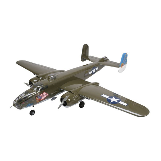
- Page 2 B-25 Mitchell ARF ASSEMBLY MANUAL Specifications Wingspan ........80.7 in (2050mm) Engine Size ....32–.40 2-stroke glow engine Overall Length ......63.0 in (1600mm) Motor Size ....Power 46 BL outrunner motor Wing Area ......851 sq in (54.9 sq dm) Radio..........6 channels or more Flying Weight .....
-
Page 3: Table Of Contents
Table of Contents Section 1: Hinging the Flaps and Ailerons ..11 Using the Manual ......3 Section 2: Aileron Servo Installation. -
Page 4: Using The Manual
Using the Manual This manual is divided into sections to help make assembly easier to understand, and to provide breaks between each major section. In addition, check boxes have been placed next to each step to keep track of each step completed. Steps with a single box ( ) are performed once, while steps with two boxes ( ) indicate that the step will require repeating, such as for a right or left wing panel, two servos, etc. -
Page 5: Radio And Power Systems Requirements
Radio and Power Systems Requirements Required Servo Extensions 7-Channel Radio Setup: Channel Function Extension Notes 1 and 7 Throttle 18-inch (JSP98120) (2), 6-inch (JSP98110) (2) Aileron 18-inch (JSP98120) (2), “Y” harness (JSP98020) Elevator None Rudder/Nose wheel “Y” harness (JSP98020) (2), 24-inch (JSP98040) Reverse servo required for nose wheel Retracts None... -
Page 6: Recommended Jr, Jr Sport And Spektrum Systems
Recommended JR, JR SPORT and Spektrum Systems JR XP9303 Spektrum DX7 JR XP7202 Recommended Setup–Glow Recommended Setup–Electric Spektrum is used with permission of Bachmann Industries, Inc. -
Page 7: Fs One (Precision Flight Simulator) W/Mode 2 Controller
Field Equipment HANS2000 Optional Retracts Hangar 9 offers two versions of Robart retractable landing gear for the B-25 Mitchell: HANB25 (Includes the following parts) HANB25S (Includes the following parts) In addition, you are required to supply:... -
Page 8: Contents Of Kit And Replacement Parts
Items not shown HAN4462 Push Rod Set HAN4467 Decal Sheet (Nose Art) HAN4457 Cowl (ea.) ™ The following Hangar 9 Pro-Lite wheels can be used as replacements for the B-25: 8. HAN304 Nose wheel 2 -inch (63mm) 9. HAN307 Main wheel 3... -
Page 9: Warranty Period
Warranty Period from defects in materials and workmanship at the date of purchase by the Purchaser. Limited Warranty those Products purchased from an authorized Horizon dealer. Third party transactions are not covered by this warranty. Proof of purchase is required for warranty claims. Further, Horizon reserves the right to change or modify this warranty without notice and disclaims all other warranties, express or implied. -
Page 10: Questions, Assistance, And Repairs
Questions, Assistance, and Repairs Your local hobby store and/or place of purchase cannot provide warranty support or repair. Once assembly, setup or use of the Product has been started, you must contact Horizon directly. This will enable Horizon to better answer your questions and service you in the event that you may need any assistance. -
Page 11: Safety, Precautions, And Warnings
Safety, Precautions, and Warnings This model is controlled by a radio signal that is subject to interference from many sources outside your control. This interference can cause momentary loss of control so it is advisable to always keep a safe distance in all directions around your model, as this margin will help to avoid collisions or injury. -
Page 12: Section 1: Hinging The Flaps And Ailerons
Section 1: Hinging the Flaps and Ailerons Required Parts Step 3 Place a T-pin in the center of each of the eight hinges removed in Step 1. Required Tools and Adhesives Step 1 Remove the flaps and aileron from the wing panel and set aside the CA hinges. - Page 13 Section 1: Hinging the Flaps and Ailerons Step 5 Step 7 Slide the aileron and outer flap into position on the wing. After the CA has fully cured, gently pull on the wing Make sure the inboard edge of the flap near the center of and aileron to make sure the hinges are secure.
- Page 14 Section 1: Hinging the Flaps and Ailerons Step 9 Step 11 Use medium grit sandpaper to sand the flap Use medium grit sandpaper to sand the flap torque rods. Use rubbing alcohol and a paper towel torque rods. Use rubbing alcohol and a paper towel to remove any debris from the torque rod.
-
Page 15: Section 2: Aileron Servo Installation
Section 2: Aileron Servo Installation Required Parts Step 2 Position the aileron servo on the cover with the servo arm centered in the opening. Use a pencil to mark the cover where the flap servo is positioned. x 1/4-inch (28mm x 6mm) dowel x 5/16-inch (28mm x 8mm) dowel (2) Required Tools and Adhesives Step 3... - Page 16 Section 2: Aileron Servo Installation Step 4 Step 6 Position the servo between the servo mounting Apply a few drops of thin CA into each of the holes to blocks. Make sure the servo is not resting on the harden the surrounding wood to provide a stronger servo cover, which will transfer vibrations to the servo.
- Page 17 Section 2: Aileron Servo Installation Step 8 Step 10 Secure an 18-inch (457mm) servo extension to the servo Use a drill and 1/16-inch (1.5mm) drill bit to drill four lead for the aileron. Make sure to secure the servo lead holes, approximately 1/8-inch (3mm) from the corners of to the extension using string or a commercially available the servo cover.
- Page 18 Section 2: Aileron Servo Installation Step 12 Step 13 Cut two 1/4-inch (4mm) long pieces from the heat Remove the backplate from a control horn. Connect the shrink tubing and slide it onto each of the clevises. clevis to the horn and position the horn so the pushrod Thread a nylon clevis onto the 6-inch (152mm) aileron is parallel to the servo horn.
- Page 19 Section 2: Aileron Servo Installation Step 14 Step 16 Use a drill and 5/32-inch (2mm) drill bit to drill the three Attach the control horn to the aileron using three mounting holes through the aileron. 2-56 x 7/8-inch machine screws and the control horn backplate.
- Page 20 Section 2: Aileron Servo Installation Step 17 Step 19 Hold the aileron so it is aligned in the centered position. Use 30-minute epoxy to glue the 1 x 5/16-inch With the servo centered, use a felt-tipped pen to mark (28mm x 8mm) wing dowel in the wing. Press the where the pushrod crosses the servo arm.
-
Page 21: Section 3: Fixed Flap Linkage Installation
Section 3: Fixed Flap Linkage Installation Required Parts Step 2 Sand the flap stay using medium grit sandpaper. Use rubbing alcohol and a paper towel to remove any dirt and debris from the flap stay. This will help in strengthening the bond between the flap stay and wing rib. - Page 22 Section 3: Fixed Flap Linkage Installation Step 5 Step 7 Attach the clevises to the flap control horns. Bend the pushrod wire 90 degrees at the mark made in the previous step. Step 6 Step 8 Hold the flap so it is aligned in the centered position. Use a felt-tipped pen to mark where the pushrod crosses the Use the pushrod connector to secure the linkage to the flap stay.
-
Page 23: Section 4: Operation Flap Linkage Installation
Section 4: Operation Flap Linkage Installation Required Parts Step 2 Position the flap servo in the opening. Route the servo lead out of the opening where the aileron extension is located. The horn on the servo will be toward the leading edge of the wing. - Page 24 Section 4: Operation Flap Linkage Installation Step 4 Step 6 Apply a few drops of thin CA to each of the holes drilled The string will now be attached to the flap servo lead and in the previous step. This will help harden the wood, to the aileron extension.
- Page 25 Section 4: Operation Flap Linkage Installation Step 8 Step 10 Cut two 1/4-inch (4mm) long pieces from the heat shrink Bend the pushrod wire 90 degrees at the mark made in the tubing and slide it onto each of the clevises. Thread the previous step.
- Page 26 Section 4: Operation Flap Linkage Installation Step 12 Adjust the position of the clevises so the flaps are aligned with the trailing edge of the wing when the flap servo is in the up position. Use the heat shrink tubing and heat gun to make sure the clevises will not become disconnected from the flap control horns.
-
Page 27: Section 5: Electric Motor Installation
Section 5: Electric Motor Installation Required Parts Step 2 Enlarge the holes for the motor standoff screws using a drill and 5/32-inch (4mm) drill bit. -inch (45mm) motor standoff (2) Required Tools and Adhesives Step 3 Step 1 Use a drill and a 5/32-inch (4mm) drill bit to enlarge the Tape the appropriate template to the front of the engine nacelle. - Page 28 Section 5: Electric Motor Installation Step 4 Step 6 Attach the motor to the standoffs using four 8-32 x supplied with the motor. 3/4-inch socket head screws. Tighten all the screws at this time. Important: Use threadlock on Note: Use threadlock on all eight of the any metal-to-metal fasteners.
- Page 29 Section 5: Electric Motor Installation Step 8 Step 10 Use hobby scissors and a rotary tool with a small sanding Use 30-minute epoxy to glue the dummy engine inside drum to make a round opening in the dummy engine for the cowling.
- Page 30 Section 5: Electric Motor Installation Step 12 Step 14 Slide the cowling onto the nacelle and align the opening Apply a few drops of thin CA to each of the holes drilled in the dummy engine with the propeller adapter of the in the previous step.
-
Page 31: Section 6: Glow Engine Installation
Section 6: Glow Engine Installation Required Parts Step 1 Tape the appropriate template to the front of the engine nacelle. Use a drill and a 1/16-inch (1.5mm) drill bit to drill the four locations for the motor mount blind nuts. and also drill the hole for the throttle pushrod. - Page 32 Section 6: Glow Engine Installation Step 3 Step 5 Use a short 8-32 socket head bolt and 9-64-inch Use medium CA to glue the pushrod housing into the ball driver to draw the 8-32 blind nuts into the back side firewall.
- Page 33 Section 6: Glow Engine Installation Step 7 Step 9 Attach the engine to the engine mount using four Slide the pushrod into the pushrod tube. Secure the engine mount to the firewall using four 8-32 x 1 -inch and four 4-40 locknuts. The included engine mount is drilled for the Evolution 36NT.
- Page 34 Section 6: Glow Engine Installation Step 11 Step 14 Slide the pushrod connector into the hole. Position the servo in the opening with the servo arm facing the rear of the necelle. Mark the locations for the servo mounting screws using a felt-tipped pen. Step 12 Secure the connector using a 2mm washer and C-clip.
- Page 35 Section 6: Glow Engine Installation Step 16 Step 18 Apply a few drops of thin CA into each hole to harden the Electronically move the throttle servo to low, and surrounding wood. You may need to run the drill bit back physically close the carburetor.
- Page 36 Section 6: Glow Engine Installation Step 20 Step 22 Attach the muffler to the engine following the instructions Insert the tank into the fuselage, guiding the tubes though provided with the engine. the opening in the center of the firewall. Step 23 Step 21 Secure the tank using the 1/4 x 1/4-inch stick provided...
- Page 37 Section 6: Glow Engine Installation Step 24 Step 26 We used a fuel dot on the line to the needle valve that will Use hobby scissors and a rotary tool with a small sanding mount to the cowling, making fueling the engine much drum to make a round opening in the dummy engine for easier when the cowl has been installed.
- Page 38 Section 6: Glow Engine Installation Step 28 Step 30 Tape four pieces of card stock to the engine nacelle. Align Drill four locations for the mounting screws using a the card stock so the ends align with the front edge of the 1/16-inch (1.5mm) drill bit.
- Page 39 Section 6: Glow Engine Installation Step 32 Step 34 Secure the cowling to the engine nacelle using four Cut the necessary openings in the cowling for the muffler, glow plug and fuel dot. Attach the propeller using a scale propeller nut. Step 35 Step 33 Repeat Steps 1 through 34 for the remaining engine...
-
Page 40: Section 7: Fixed Landing Gear Installation
Section 7: Fixed Landing Gear Installation Required Parts Step 2 Attach the 5/32-inch wheel collar to the landing gear using a 3mm setscrew and the included 1.5mm hex wrench. Use threadlock on the setscrew to prevent it from vibrating loose. -inch (63mm) -inch (82mm) (2) Required Tools and Adhesives... - Page 41 Section 7: Fixed Landing Gear Installation Step 4 Step 6 Slide the main gear into the engine nacelle. Enlarge the holes in the gear rails ONLY using a 7/64-inch (3mm) drill bit. Note: Wheel not shown for clarity. Step 7 Step 5 Secure the main gear in the engine nacelle using four Use a drill and 5/64-inch (2mm) drill bit to drill four...
- Page 42 Section 7: Fixed Landing Gear Installation Step 9 Step 11 Slide the steering arm onto the nose gear wire. Next, Prepare four 3mm x 25mm machine screws by sliding a slide the mount on the wire, then a wheel collar. The 3mm washer on each screw.
- Page 43 Section 7: Fixed Landing Gear Installation Note: Use threadlock on all four of Step 15 the 3mm nuts to prevent vibrations Apply a few drops of thin CA into each hole to harden the from loosening them. surrounding wood. You may need to run the drill bit back through the holes after applying the CA.
- Page 44 Section 7: Fixed Landing Gear Installation Step 17 Step 19 Connect the pull-pull cable to the steering arm using Repeat the crimping process, aligning the marks made two crimps. Pass the cable through a crimp, through on the cable with the hole in the fastener. Cut any excess the fasteners then back through the crimp.
-
Page 45: Section 8: Retractable Landing Gear Installation
Robart retractable landing gear. Set the nose gear unit onto the mounting rails with the Hangar 9 offers two types of optional of Robart retractable retract placed up against the front firewall and mark the landing gear for the B-25 Mitchell. - Page 46 Section 8: Retractable Landing Gear Installation Step 4 Step 6 From the back side of the mounting rails, insert the four Install 16 inches (406mm) of each color of air line onto 4-40 blind nuts and use a 4-40 bolt with a washer to draw each of the air cylinder inlets on the landing gear.
- Page 47 Section 8: Retractable Landing Gear Installation Step 7 Set the nose gear retract onto the mounting rails. Place head bolts, then securely fasten the retract to the mounting rails with these four 4-40 x 1-inch bolts Step 9 Cut two 12-inch (305mm) lengths of pull-pull wire for the steering.
- Page 48 Section 8: Retractable Landing Gear Installation Step 10 Step 12 Remove the standard servo arm and attach a large Apply a few drops of thin CA into each hole to harden the 180-degree standard arm on the servo. Position the surrounding wood.
- Page 49 Section 8: Retractable Landing Gear Installation Step 14 Step 16 Center the nose gear and steering servo. Thread a clevis Use a rotary tool and sanding drum to remove the area on the threaded rigging couplers and attach them to the of the nose gear cover to allow the nose wheel strut and steering servo arm.
- Page 50 Section 8: Retractable Landing Gear Installation Step 17 Step 19 We installed a rubber band to help hold the pull/pull Set the main gear onto the mounting rails and mark the cables clear of the nose wheel and strut when it is mounting hole locations.
- Page 51 Section 8: Retractable Landing Gear Installation Step 21 Step 23 From the back side of the mounting rails, insert the Set the main gear retract onto the mounting rails. Place four 4-40 blind nuts and use a 4-40 bolt with a washer to draw each blind nut into each one of the four holes head bolts, then securely fasten the retract to the mounting just drilled.
- Page 52 Section 8: Retractable Landing Gear Installation Step 24 Step 25 Route the air lines from the retract unit through the nacelle Install the main wheel onto a wheel axle and then install loosely. If you are installing the retracts and the wing extensions are already in place, then you will need to use and axle into the strut.
-
Page 53: Section 9: Retract Valve And Hardware
Section 9: Retract Valve and Hardware All pushrod hardware and mounting plates are supplied Step 2 by the modeler. We use a plastic 2-56 clevis to attach a 2-56 pushrod to Step 1 end of the pushrod where it attaches to the servo arm. The You will need to fabricate a plywood plate to mount the pushrod should be placed on the servo arm a distance servo and the retract valve on. - Page 54 Section 9: Retract Valve and Hardware Step 4 Step 5 Install the air tank in the pre-cut position below the You will need to make a decision at this time about radio tray. Follow the installation diagram instructions transporting the model. If you plan on taking the two from Robart to hook up the remaining air lines.
-
Page 55: Section 10: Engine Nacelle Installation
Section 10: Engine Nacelle Installation Required Parts Step 2 Place the nacelle support plate over the holes in the trailing edge of the wing and trace the outline of the plate onto the wing. x 1/4-inch (28mm x 4mm) dowel (4) Required Tools and Adhesives Step 1 Use a short 8-32 socket head bolt and 9/64-inch ball... - Page 56 Section 10: Engine Nacelle Installation Step 4 Step 6 Use 30-minute epoxy to glue the plate on the wing. Secure a 12-inch (305mm) servo extension to the throttle (or speed control) lead. Tie the string around the end of the extension as shown. Step 5 Use 30-minute epoxy to glue the two 1 x 1/4-inch...
- Page 57 Section 10: Engine Nacelle Installation Step 8 Step 10 Attach the engine nacelle to the wing using two 8-32 x Use a sharp hobby knife to remove a 1/8-inch (3mm) wide strip to the inside of the line drawn in the previous step. Note: Use threadlock on all screws to keep Step 11 them from coming loose during flight.
-
Page 58: Section 11: Wing Installation
Section 11: Wing Installation Required Parts Step 3 Hold the wing bolt plate centered on the wing center section. Use a felt-tipped pen to mark the location for one of the holes in the plate. -inch socket head bolt (2) Required Tools and Adhesives Step 1 Slide the wing tube into one of the wing panels. - Page 59 Section 11: Wing Installation Note: The Step 7 is for the EP version Step 5 only. Skip to Step 8 when building Use a wing bolt to keep the plate aligned at the first hole the glow powered version. and mark the location for the second hole on the plate. Step 7 When building an EP version of your B-25, attach the batteries to the battery tray with hook and loop straps.
-
Page 60: Section 12: Rudder And Servo Installation
Section 12: Rudder and Servo Installation Required Parts Step 3 Use a drill and 1/16-inch (1.5mm) drill bit to drill four holes, approximately 1/8-inch (3mm) from the corners of the servo cover. Required Tools and Adhesives Step 1 Mounting the rudder servo follows the same procedure Step 4 as mounting the aileron servo (Section 2: Aileron Servo Apply a few drops of thin CA to each of the holes to... - Page 61 Section 12: Rudder and Servo Installation Step 5 Step 7 Use 30-minute epoxy to attach the fin to the stabilizer. metal screws. 90-degrees Note: Make sure the vertical fins remain in alignment while the epoxy cures. Step 6 Use a sharp hobby knife to remove the covering from the Step 8 fin where the tab from the stabilizer will be inserted.
- Page 62 Section 12: Rudder and Servo Installation Step 9 Step 12 Use a rotary tool and 1/16-inch (1.5mm) drill bit to drill Slide the rudder into position on the fin. Make sure the a 1/2-inch (12mm) deep hole in the center of each hinge rudder can move without binding against the fin at the top slot for the rudders and fins.
- Page 63 Section 12: Rudder and Servo Installation Step 14 Step 16 After the CA has fully cured, gently pull on the rudder Use medium grit sandpaper to sand the evevator torque and fin to make sure the hinges are secure. If not, re-glue rods.
- Page 64 Section 12: Rudder and Servo Installation Step 19 Step 21 Remove the backplate from a control horn. Thread a clevis Drill the three holes for the control horn mounting screw onto the 2-inch (51mm) rudder pushrod and attach the and harden the surrounding wood with thin CA. Mount the clevis to the control horn.
-
Page 65: Section 13: Tail Section Installation
Section 13: Tail Section Installation Required Parts Step 2 Use a short 8-32 socket head bolt, 9/64-inch hex driver and washer to draw the blind nut into the fuselage as shown. x 1/4-inch (28mm x 4mm) dowel Required Tools and Adhesives Step 1 Use 30-minute epoxy to glue the 1 x 1/4-inch... - Page 66 Section 13: Tail Section Installation Step 4 Step 6 Secure the stabilizer using a 9/64-inch hex driver, 3/8-inch (10mm) wide section of covering inside the lines drawn in the previous step. Use care not to cut into the underlying wood of the stabilizer. Note: You must use threadlock on the bolt holding the stabilizer to the fuselage.
- Page 67 Section 13: Tail Section Installation Step 8 Step 10 Mix up 1/2-ounce (15Ml) of 30-minute epoxy. Apply the Use a drill and 1/16-inch (1.5mm) drill bit to drill the epoxy to the exposed wood of the stabilizer. The stabilizer locations for the servo mounting screws. should then be bolted into place.
- Page 68 Section 13: Tail Section Installation Step 12 Step 14 Secure the elevator servo in the fuselage using the Connect the pushrod to the servo arm as shown. hardware provided with the servo. Step 13 Remove the supplied servo arm from the servo. Cut one arm from a medium-length servo arm so it won't interfere with the operation of the elevator.
-
Page 69: Section 14: Receiver, Battery And Scale Accessories
Section 14: Receiver, Battery and Scale Accessories Required Parts Step 1 Wrap the receiver in foam and plug any necessary extensions and Y-harnesses into the appropriate channels. Secure the receiver to the radio plate using a hook and loop strap. The quantity of the following two items will depend on receiver used. - Page 70 Section 14: Receiver, Battery and Scale Accessories Step 3 Step 5 Glue the 128mm x 45mm x 3mm battery tray into the front of the fuselage using 30-minute epoxy. Wrap the receiver front greenhouse canopy to the fuselage. There are two battery in 1/4-inch (4mm) foam.
- Page 71 Section 14: Receiver, Battery and Scale Accessories Step 7 Step 8 Use hobby scissors to trim the rear gun mount. Use rear canopy to the fuselage and stabilizer. There are two RC-56 canopy glue to secure the mount to the end of the screws on either side of the fuselage, two on each side fuselage.
- Page 72 Section 14: Receiver, Battery and Scale Accessories Step 10 Step 12 Glue the turret and guns following the procedure you have Use 30-minute epoxy to glue the radio antenna to the followed in previous steps. nose wheel steering servo access hatch. Step 13 Step 11 Attach the side guns behind the wing as shown.
-
Page 73: Recommended Center Of Gravity (Cg)
Section 14: Receiver, Battery and Scale Accessories Step 14 Step 15 All decals will be factory installed. Use RC-56 canopy glue to attach the radiators to the wing. Step 16 Repeat Steps 13 though 15 to install the remaining accessories, as there is a right and left to these accessories. -
Page 74: Control Throws
Control Throws The amount of control throw should be adjusted as closely Aileron Low Rate as possible using mechanical means, rather than making 10 degrees, 3/8-inch or 9.5mm up/down large changes electronically at the radio. By moving Aileron High Rate the position of the clevis at the control horn toward the outermost hole, you will decrease the amount of control 15 degrees, 9/16-inch or 14mm up/down... -
Page 75: Retract Air Line Routing Diagram
Retract Air line Routing Diagram Retaining nuts are optional roba rt roba rt 3 GEAR INSTALLATION Optional On-board Right Landing Pressure Gauge #173 Gear Cylinder (NOT INCLUDED) Included in the VRX Kits Fill Chuck Fill Valve (AIR SUPPLY IN) Nose Fittings Gear Cylinder... -
Page 76: Pre-Flight
Pre-Flight Check the radio installation and make sure all the Charge both the transmitter and receiver pack for your control surfaces are moving correctly (i.e. the correct airplane. Use the recommended charger supplied with direction and with the recommended throws). Test run your particular radio system, following the instructions the engine and make sure it transitions smoothly from provided with the radio. -
Page 77: Takeoff
Takeoff Prior to your first flight we recommend that you do Familiarize yourself with the flight characteristics of the some low speed taxi tests. Use these tests to center B-25 and practice flying the model at a safe height using the nose wheel steering to allow for a takeoff straight both the mid and full flap positions. -
Page 78: Engine Out
Remember you do not have enough power to climb out from a missed landing, so plan your approach the best you can. Enjoy flying your Hangar 9 B-25 Mitchell. The model is very predictable and will surely give you many hours of enjoyment. -
Page 79: 2007 Official Ama National Model Aircraft Safety Code
2007 Official AMA National Model Aircraft Safety Code GENERAL 8. I will not operate model aircraft carrying pyrotechnic devices which explode burn, or propel a projectile 1. A model aircraft shall be defined as a non-human- of any kind. Exceptions include Free Flight fuses or carrying device capable of sustained flight in the devices that burn producing smoke and are securely atmosphere. - Page 80 2007 Official AMA National Model Aircraft Safety Code Radio Control 7. With the exception of events flown under official AMA rules, no powered model may be flown outdoors closer 1. All model flying shall be conducted in a manner to than 25 feet to any individual, except for the pilot and avoid over flight of unprotected people.
- Page 81 Hangar 9 B25J Mitchell ARF Описание...
Need help?
Do you have a question about the B25J Mitchell ARF and is the answer not in the manual?
Questions and answers