Table of Contents
Advertisement
Advertisement
Table of Contents

Related Manuals for Inspire Inspire BL1


Summary of Contents for Inspire Inspire BL1
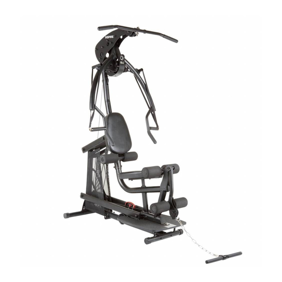
- Page 1 ASSEMBLY & OPERATION MANUAL RECORD SERIAL NUMBER HERE...
- Page 2 Certain parts including guide rods can form rust in a humid environment, resulting in impaired function. Sweden Head office Casall Sport AB Västgötegatan 7 Box 6007 600 06 Norrköping...
-
Page 3: Table Of Contents
TABLE OF CONTENTS Section Description……………………………………………………. Page Important Safety Instructions………………………………………. Tools Required………………………………………………………………… Parts & Hardware List……………………………………………………. Assembly Instructions………………………………………………..…. 3-20 Final Adjustments…………………………………………………………… Accessories……………………………………………………………………… General Maintenance Information…….…………………………… Maintenance Schedule…….………………………………………………... -
Page 4: Important Safety Instructions
IMPORTANT SAFETY INSTRUCTIONS Please read this entire manual and familiarize yourself with all decals and warnings before using this home gym. • WARNING! It is necessary to inspect this home gym regularly to maintain safety and proper function. Please use the maintenance schedule included towards the back of this manual. -
Page 5: Parts & Hardware List
PARTS & HARDWARE LIST Part # Parts Description Q'ty Part# Hardware Description Q'ty Qty Rec'd Qty Rec'd Front Foot Assembly Hex Bolt, M12*160 Base Frame Assembly Hex Bolt, M16*230 Rear Foot Assembly Hex Bolt, M10*70 Shroud Mount Rod, Lower Hex Bolt, M12*90 Shroud Mount Bracket, Upper Hex Bolt, M10*60 Weight Selector Tube... -
Page 6: Assembly Instructions
ASSEMBLY INSTRUCTIONS PAGE 3... -
Page 7: Front Foot Assembly 1
STEP 1 Attach Front Foot Assembly (#1) to Base Frame Assembly (#2) using: Two (M10x70 Bolts) Attach Rear Foot Assembly (#3) to Base Frame Assembly (#2) using: Two (M10x70 Bolts) Wrench tighten all bolts now. Page 4 5/11... -
Page 8: Weight Selector Tube 1
STEP 2 Attach Slider Assembly (#7) to Weight Selector Tube(#6). Install M5x10 Screw (#106) into Weight Selector Stem (#6) and tighten. Insert two Step Bushings (#40) into the Weight Selector Tube (#6). Attach two 3 ½” Pulleys (#37) and two 1” long Barrel Spacers (#51) to Weight Selector Tube (#6) using: Two (M10x70 Bolts) Wrench Tighten Bolts Now. - Page 9 STEP 3 Attach Weight Selector Tube (#6) to Base Frame Assembly (#2) using: One (M12x90 Bolt) Wrench tighten bolt so there is a slight drag when moving Weight Selector Tube. Do not over tighten. Page 6 12/11...
-
Page 10: Lower Arm (
STEP 4 Attach Lower Arms (#8) to Base Frame Assembly (#2) using: One (M16x230 Hex Bolt) Attach Upper Arms (#9) to Base Frame Assembly (#2) using: One (M16x230 Hex Bolt) Wrench Tighten bolts so there is a slight drag on the Arms when moved. Do not over tighten. - Page 11 STEP 5 Attach Lower Main Frame (#11) to Foot Plate (#65) using: Three (M10x60 Hex Bolt) Wrench Tighten Now. Page 8 5/11...
- Page 12 STEP 6 Attach Lower Main Frame (#11) to Lower Arms (#8) using: One (M16x230 Hex Bolt) Wrench Tighten bolt so there is a slight drag when moving Lower Main Frame. Do not over tighten . Page 9 12/11...
- Page 13 STEP 7 Attach Upper Main Frame (#10) to Lower Main Frame (#11) using: Four (M10*90 Allen Head Screws) Attach Upper Main Frame (#10) to Left & Right Upper Arms (#8 & #9) using: One (M16*230 Hex Bolt) Wrench tighten bolts now. Page 10 5/11...
-
Page 14: Top Beam Plate (
STEP 8 Attach Top Beam Plates (#13) and One 3 ½” Pulley (#37) to Upper Main Frame (#10) using: Four (M10*100 Hex Bolts) Two (1” Long barrel Spacers) Finger Tighten Only Attach Lat Bar Holders (#50) and One 3 ½” Pulley (#37) to Top Beam Plates (#13) Using: One (M10*115 Hex Bolt) One (M10*100 Hex Bolt) One (3”... -
Page 15: Press Arm Mount 1
STEP 9 Attach Press Arm Mount (#14) to Top Beam Plates (#13) using: One (M12*100 Hex Bolt) Wrench Tighten bolt #88 so there is a slight drag when moving Press Arm Mount. Do not over tighten . Wrench tighten all bolts installed in Step 8. Attach Pop-Pin Shaft (#47) to Upper Main Frame (#10) Thread Completely and Wrench Tighten. - Page 16 STEP 10 Attach Press Arm (#18) to Press Arm Mount (#14) using: One (M12*160 Hex Bolt) Wrench Tighten bolt so there is a slight drag when moving Press Arm. Do not over tighten . Page 13 12/11...
- Page 17 STEP 11 Attach Leg Extension Assembly (#24) to Lower Main Frame (#11) using: One (M12*80 Hex Bolt) Wrench Tighten bolt so there is a slight drag when moving Leg Extension Assembly. Do not over tighten . Attach Press Arm Mount Cover Plate (#16) using: One (M5*12 Philips head Screw) Wrench Tighten Now.
- Page 18 STEP 12 Attach Back Pad Tilt Frame (#20) to Upper Main Frame (#10) using: One Roller Tube (#21) Two M6*8 Set Screws (#98) Two Foam Rollers (#44) One M6*75 Button Head Screw (#93) Two Large Plastic Washers (#43) One M6 Flat Head Nut (#99) Two End Caps (#45) Wrench Tighten bolt #93 so there is a slight drag when moving Back Pad tilt Frame.
-
Page 19: Backpad Tilt Frame 1
STEP 13 Attach Seat Pad (#53) to Seat Stem (#23) using: Two (M10*40 Hex Bolts) Wrench Tighten Now. Slide Seat Stem (#23) into Lower Main Frame (#11) Attach Back Pad (#53) to Backpad Tilt Frame (#20) using: Two (M10*15 Flat Head Screws) Wrench Tighten Now. -
Page 20: Roller Tube 3
STEP 14 Attach 4 Foam Rollers (#44) to Leg Extension Assembly (#24) & Seat Stem (#23) using: Two Roller Tubes (#21) Four End Caps (#45) Page 17 12/11... - Page 21 STEP 15 Pulley 1 Pulley2 Pulley 3 Pulley 4 Pulley 5 Pulley 6 Pulley 8 Pulley 11 Pulley 9 Pulley 7 Pulley 10 Began at the top of the machine and run the cable sequentially from pulley #1 to pulley #11, as shown in the above drawing.
- Page 22 STEP 16 Attach Left and Right Shrouds (#38L & #38R) by first slipping the top of each Shroud onto the horns of the upper shroud mount (#5), as shown above. Make sure seams are to the inside. Next, slide rods (#4) into the bottom of each shroud and attach to frame using: Four M6*12 Button Head Screws Note: Be sure to pull the shrouds down taut before tightening the four screws.
-
Page 23: Chain (
STEP 17 Attach Lat Bar (#17) to Spring Clip (#73). Attach Chain (#26) to Spring Clip (#73) on the end of the Cable. Attach Revolving Curl Bar (#25) to Chain (#26) with Spring Clip (#73). Page 20 5/11... -
Page 24: Final Adjustments
FINAL ADJUSTMENTS AFTER ASSEMBLY Press Arm Stop Macro Cable Adjustment Nut #2 Nut #1 Weight Selector Handle Wooden Platform Weight Selector Rollers Front Rubber Bumper FINAL ADJUSTMENT: (if needed) Below the seat you will find the weight selector. Grab the weight selector handle and pull the spring loaded pin. -
Page 25: Accessories
ACCESSORIES • Exercise Wall Chart • Lat Bar • Revolving Curl Bar HOME GYM OPTIONS • D handles • Aluminum EZ Curl Bar • Ab Crunch Bar Training Tips CONSULT A PHYSICIAN BEFORE STARTING ANY EXERCISE PROGRAM 1. Always warm up before you start weight training. This helps get your muscles warm and prevents injury. -
Page 26: General Maintenance Information
GENERAL MAINTENANCE INFORMATION • Periodically inspect the cables for splitting, cracking or fraying. Also, watch for bulging or flat areas in the cable. • Immediately replace cables at the first signs of damage or wear. Never use equipment with damaged or worn cables. •... -
Page 27: Maintenance Schedule
MAINTENANCE SCHEDULE HOME ROUTINE ENTRY DATE MAINTENANCE Inspect: Links, Pull Pins, WEEKLY Spring Clips, Swivels, Weight Stack Pins WEEKLY Clean: Upholstery Inspect: Cables and WEEKLY their Fittings Inspect: Tautness of all WEEKLY Shrouds Inspect: Accessory Bars 3 MONTHS and Handles 3 MONTHS Inspect: All Decals Inspect: All Nuts and...
Need help?
Do you have a question about the Inspire BL1 and is the answer not in the manual?
Questions and answers