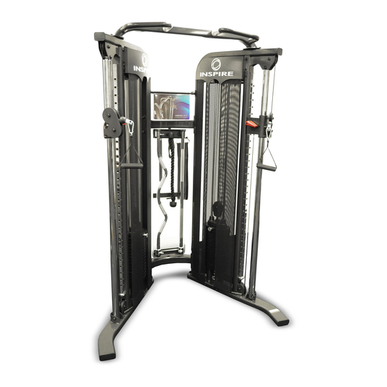
Inspire FT1 Assembly & Operation Manual
Hide thumbs
Also See for FT1:
- Assembly & operation manual (13 pages) ,
- Assembly & operation manual (33 pages)

Related Manuals for Inspire FT1


Summary of Contents for Inspire FT1
- Page 1 ASSEMBLY & OPERATION MANUAL RECORD SERIAL NUMBER HERE www.inspirefitness.net by Health In Motion LLC June 2011...
- Page 2 Use only Inspire replacement parts on this machine. The use of any other brand of parts can also result in a loss of warranty. If you need help finding an authorized retailer, please contact us directly: Inspire Fitness 4945 East Hunter Ave. Anaheim, CA 92807...
-
Page 3: Important Safety Notice
IMPORTANT SAFETY NOTICE PRECAUTIONS This exercise machine is built for optimum safety. However, certain precautions apply whenever you operate a piece of exercise equipment. Be sure to read the entire manual before you assemble or operate your machine. In particular, note the following safety precautions: 1. -
Page 4: Parts List
PARTS LIST Q'ty Q'ty Part# Part# Description Description (pcs) (pcs) Right Station Assembly Left Inner Logo Plate Left Station Assembly Shroud Mount Bar Upper Frame Assembly Hanger Panel Lower Cross Brace Height Adjustment Handle Upper Cross Brace Rubber Bumper Guide Rod Bracket&Ring Cap Plastic Washer Guide Rod Hook... - Page 5 HARDWARE SIZING CHART PAGE 4 6/2011...
- Page 6 FUNCTIONAL TRAINER ASSEMBLY INSTRUCTIONS STEP 1 (See Diagram 1) A.) Do not tighten the Nuts and Bolts until instructed to do so. B.) Place the Lower Cross Brace (#4) between the Right & Left Stations (#1 & #2) in the mid-span. C.) Attach one end of the Lower Cross Brace to the Right Station.
- Page 7 Diagram 1 PAGE 6 6/2011...
- Page 8 STEP 2 (See Diagram 2) A.) Lift up the Selector Stem (#10) on the Right Station (#1) and hold it still to release the tension on the cables. Remove the two M10 x ¾ ” Allen Bolts (#44), Ø ¾ ” Spring Washers (#47), and Ø 1” Washers (#50) which were pre-assembled in the factory to hold the Guide Rod Bracket (#6).
- Page 9 Diagram 2 PAGE 8 6/2011...
- Page 10 STEP 3 (See Diagram 3) A.) Slide a Plastic Washer (#38) onto the axle on Upper Hanger Bracket (#14). Insert the axle through the Upper Cross Brace (#5) from bottom. Secure it with one M8 x ½ ” Allen Bolt (#46), one Ø 7/8”...
- Page 11 Diagram 3 PAGE 10 6/2011...
- Page 12 STEP 4 (See Diagram 4) (Attach Shrouds) Start on the Right Side of the gym. A.) Slide two panels of the Inner Fabric Shroud (#28) onto a Shroud Mount Bar (#34) so the seams face inside. Attach the Shroud Mount Bar (#34) to the inside upper frame as shown, using two M8x5/8”...
- Page 13 Diagram 4 PAGE 12 6/2011...
- Page 14 STEP 5 (See Diagram 5) A.) Attach one Exercise Chart Hanger Bracket (#8) to the Right Station (#1). Secure it with two M6 x 5/8” Allen Bolts (#40) and Ø ¾ ” Washers (#51). Do not tighten the Bolts yet. B.) Slide the Flip Exercise Chart (#57) onto the Exercise Chart Hanger (#15).
- Page 15 Diagram 5 PAGE 14 6/2011...
- Page 16 STEP 6 (See Diagram 6) A.) Attach the Height Adjustment Handle (#36) to the Right Lock Switch (#10) on the Pulley Carriage (#8) Not Shown on Diagram. Secure it with one M5 x 3/8” Allen Bolt (#45). Repeat the same procedure to install the other side.
- Page 17 Diagram 6 PAGE 16 6/2011...
- Page 18 PAGE 17 6/2011...
-
Page 19: General Maintenance Information
GENERAL MAINTENANCE INFORMATION Warning: DO NOT place styrofoam or printed materials on the orthopedic seat pads. Over time, these may stick to the pads and mar the surface. Do not leave items sitting on the orthopedic seat pads, these pads have a special density that takes shape to objects and small objects will leave imprints in the surface that may take time to come out. -
Page 20: Maintenance Schedule
MAINTENANCE SCHEDULE HOME ROUTINE ENTRY DATE MAINTENANCE Inspect: Links, Pull Pins, WEEKLY Snap Links, Swivels, Weight Stack Pins WEEKLY Clean: Upholstery Inspect: Cables and WEEKLY their Fittings Inspect: Tautness of all WEEKLY Shrouds Inspect: Accessory Bars 3 MONTHS and Handles 3 MONTHS Inspect: All Decals Inspect: All Nuts and... -
Page 21: Limited Warranty
LIMITED WARRANTY In-Home Lifetime Warranty. This Warranty applies only in the United States to Inspire strength products manufactured or distributed by Health In Motion LLC. The warranty period to the original purchaser is lifetime of the original purchaser. Health In Motion warrants that the Product you have purchased for non -commercial, personal, family or household use from Health In Motion LLC or from an authorized Health In Motion reseller is free from defects in materials or workmanship under normal use during the warranty period.
Need help?
Do you have a question about the FT1 and is the answer not in the manual?
Questions and answers