Advertisement
NOTE:
Please read all
instructions carefully
before using this
product.
Table of Contents
Safety Notice
Rower
Hardware Identifier
Assembly Instructions
CR 2
Parts list
Exploded Diagram
Warranty
MODEL
CR 2
Retain This
Manual for
Reference
12-01-2014
OWNER'S
MANUAL
4945 East Hunter Ave., Anaheim, CA 92807
Tel:(877) 738-1729 Fax: (714) 738-1728
www.inspirefitness.net
Advertisement
Table of Contents

Related Manuals for Inspire CR 2


Summary of Contents for Inspire CR 2
- Page 1 NOTE: Please read all instructions carefully before using this product. Table of Contents Safety Notice Rower Hardware Identifier Assembly Instructions CR 2 Parts list Exploded Diagram Warranty MODEL CR 2 Retain This Manual for Reference 12-01-2014 OWNER’S MANUAL 4945 East Hunter Ave., Anaheim, CA 92807 Tel:(877) 738-1729 Fax: (714) 738-1728 www.inspirefitness.net...
-
Page 2: Table Of Contents
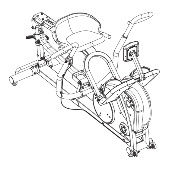
Warranty ....................23 Before You Begin Thank you for selecting the INSPIRE CROSS ROW. For your safety and benefit, read this manual carefully before using the machine. As a manufacturer, we are committed to providing you complete customer satisfaction. If you have any questions, or find there are missing or damaged parts, please call our TOLL- FREE customer service number. -
Page 3: Important Safety Notices
IMPORTANT SAFETY NOTICE PRECAUTIONS This exercise machine is built for optimum safety. However, certain precautions apply whenever you operate a piece of exercise equipment. Be sure to read the entire manual before you assemble or operate your machine. In particular, note the following safety precautions: 1. -
Page 4: Warning Label Placement
Warning Label Placement PAGE 4... -
Page 5: Hardware
Contents of Packaging TOOL STEP1 STEP2 STEP3 STEP4 STEP6 PAGE 5... - Page 6 CR2 Hardware Pack STEP1 STEP2 STEP3 STEP4 STEP6 NOTE: The following parts are not drawn to scale. Please use your own ruler or scale to measure the size. PAGE 6...
-
Page 7: Assembly Instructions
Step 1 Attach and tighten the Rear Stabilizer Tube Assembly (26) to the frame (24) using 4 – M10x20 Socket Head Screws (132), 4 – M10 Spring Washers (133), and 4 – M10 Curved Washers (134). PAGE 7... - Page 8 Step 2 Attach the Seat Handle Bar (22) to the Seat Slider (54) using 4 – M8x16 Socket Head Screws (19), 4 – M8 Spring Washers (20), and 4 –M8 Flat Washers (21). Attach the Seat Pad (17) in the orientation shown in the image and secure it to the Seat Slider (54) using 4 –...
- Page 9 GRIP SHIFTER CABLE Step 3 Attach the Push Arm (120) to the Front Vertical Linkage (125) using 4 - M8 Lock Nuts (7) and 4 - M8 Washers (13). NOTE: It is recommended that an aide hold the Push Arm in position while the Lock Nuts are installed.
- Page 10 Step 4 Position the Foot Plate Frame (10) near the Main Frame (24) and connect the Upper and Lower Computer Cables, items 118 and 117 respectively. Feed the cable wires into the frame after the connection has been made. Attach the Foot Plate Frame (10) onto the Main Frame (24) using 4 – M8 Locking Nuts (7), 4 –...
- Page 11 Step 5 Connect the Computer Console connector to the Upper Computer Cable (118) and secure the Computer Console (1) to the Console Plate (4) using 4 - M5 screws (5). PAGE 11...
- Page 12 39 39 Step 6 Attach the Plastic Shrouds 11 & 12 to the left and right sides of the Main Frame (24), respectively using 4 - M5 Screws (39) and 1 self-tapping screw (18). PAGE 12...
- Page 13 Step 7 Thread the Middle Leveling Pad until it makes contact with the floor. PAGE 13...
-
Page 14: Computer Operations Guideline
COMPUTER OPERATION This unit is equipped with a Telemetric Heart Rate transmitter that allows the user to monitor their heart rate while wearing a Chest Strap. A Chest Strap may be purchased from Inspire by calling (877) 738-1729. Display Time During a workout the time counts up from 00:00. - Page 15 2) Age Users may input their age in order to adjust the calorie counter accordingly. Entering Age a.) Press and Hold the UP + DOWN button for 2 seconds b.) AGE will begin to blink. The default is 35. Adjust the age using the arrow keys. c.) After reaching your age, hit the MODE button to save this information into the computer.
- Page 16 Focus Program Setup (Predeveloped workout sessions designed to target specific body parts chosen by the user.) Press the FOCUS button to toggle through the Focus Program options listed below. a. Arms, Legs, Full Body, off During a FOCUS workout the computer will alternate between various Focus Commands in 1:00 minute intervals.
-
Page 17: Parts List
Parts List Part # Description RM300-631-001 Computer Console 0113-208-652B M8x65 Socket Head Screw RM300-381-013 Computer Console Plate RM300-380-009 Computer Adjustable Post 0110-708-028 M8 Lock Nut RM300-801-006 Foot Strap 0113-206-138 M6x12 Socket Head Screw RM300-340-001 Foot Plate Frame RM300-801-007 Flywheel Shroud, L RM300-801-008 Flywheel Shroud, R 0116-202-088... - Page 18 0113-104-108 M4x10 Cross Head Screw RM300-801-003 Plastic Disc RM300-801-001 Shroud, L RM300-380-005 Crank Assembly 0200-231-31 Crank Bearing, 6004 RM300-501-004 Chain RM300-801-002 Housing R RM300-381-015 Silder Bracket RM300-300-001 Seat Slider RC800-801-202 Pop Pin 0111-110-058 M10x105 Hex Head Screw 0116-010-008 M10 Flat Washer 0110-710-008 M10 Locknut 0113-210-128...
- Page 19 0111-110-125 M10x125 Hex Head Screw 0113-210-138 M10x125 Socket Head Screw RM300-380-004 Rear Vertical Linkage 0113-306-168 Countersink Head Screw RM300-501-006 Belt RM300-521-004 Flywheel 0110-410-019 M10 Flange Bolt RM300-300-003 Fork -Crank Bearing Housing RM300-561-029 Brake Pad Assembly RM300-521-026 Aluminum Logo RM300-561-028 Shoulder Bolt 0117-110-998 Retaining Ring B2210-1000-015...
- Page 20 RM300-500-003 Intermediate Drive Assembly Computer, Lower Wire Computer, Upper Cable RM300-320-004 Push Arm Assembly RM300-500-001 First Stage Crank Assembly RM300-380-001 Horizontal Linkage Assembly RM300-300-002 Fork Tube Assembly RM300-380-006 Front, Vertical Linkage Assembly Flywheel Assembly RM300-520-002 Pivot Brake Arm Assembly GM575-881-005 Middle Leveling Pad 0113-210-208 M10x20 Socket Head Screw (Black)
-
Page 23: Warranty
DAMAGES, SO THE ABOVE LIMITATIONS OR EXCLUSION MAY NOT APPLY TO YOU. This Warranty gives you specific legal rights and you may also have other rights that may vary from state to state. This is the only express warranty applicable to FG1’s “Inspire”...
Need help?
Do you have a question about the CR 2 and is the answer not in the manual?
Questions and answers