
Subscribe to Our Youtube Channel
Related Manuals for Teeter Hang Ups ComforTrak Series


Summary of Contents for Teeter Hang Ups ComforTrak Series
-
Page 1: Assembly Instructions
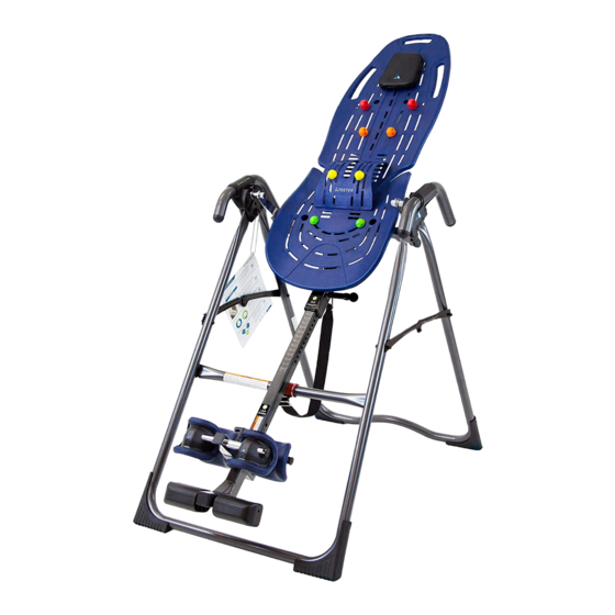
ComforTrak Series Assembly Instructions EP-560, EP-860, EP-960 & EP-970 Models www.ActiveForever.com *Inversion Table images may vary slightly from your model. The EP-560 is shown here. -
Page 2: Important Safety Instructions
BEFORE YOU BEGIN: Review all steps before beginning assembly and read all precautions before using the inversion table. Carefully adhere to the Assembly Instructions and Owner’s Manual to help ensure safety and product integrity. IMPORTANT SAFETY INSTRUCTIONS READ ALL INSTRUCTIONS BEFORE USING THE INVERSION TABLE. WARNING WARNING - To reduce the risk of injury to persons: •... - Page 3 BEFORE YOU BEGIN: Review all steps before beginning assembly and read all precautions before using the inversion table. Carefully adhere to the Assembly Instructions and Owner’s Manual to help ensure safety and product integrity. IMPORTANT SAFETY INSTRUCTIONS READ ALL INSTRUCTIONS BEFORE USING THE INVERSION TABLE. WARNING •...
-
Page 4: Table Of Contents
Items for Assembly ITEMS FOR ASSEMBLY ITEM NUMBER ITEMS FOR ASSEMBLY ITEM NUMBER ITEMS FOR ASSEMBLY ITEM NUMBER This column is ONLY for the Assembly of the A-Frame E6-1100 Handle Assembly Main Shaft with T-Pin Ankle Lock System (E6-1600) Angle Tether F5-1007 Strech Assist Handles (2) - Page 6 BEFORE BEGINNING Before reading further, study the drawing below to familiarize yourself with the important components of your new Teeter Hang Ups ® inversion table. Head Pillow Angle Tether Bed Frame Extension Crossbar ComforTrak™ Table Bed A-Frame 3-Hole Roller Hinges Main Shaft Handles Ankle Lock System...
- Page 7 WARNING LABEL PLACEMENT Important: Please review all labels and supporting materials before using your inversion table. This drawing indicates the locations of the warning labels found on your product. If a label is missing, illegible or is removed, contact Customer Service at the phone number or website found at the bottom of this page to request a complimentary replacement label.
-
Page 8: Screwdriver
Step FIGURE 1 Assemble the front Stability Feet (F7-1033) onto the A-Frame (E6-1100) Feet may come pre-assembled. • Lay the A-Frame on the floor with the Crossbar on the top side (Figure 1) to assemble the front Stability Feet. • Select the Stability Foot labeled Number 1 on the inside and place it on the RIGHT side of the A-Frame. - Page 9 Step EP-560, EP-560 Sport & EP-560 Limited Models FIGURE 4 Depending on the model you have purchased, the items in this step will vary. See “Which Model Do you Own?” (page 4) for more information. Assemble the Handles to the Table Bed (EP-1300) FIGURE 4A Bolts/Nuts may come pre-assembled in the Handles.
- Page 10 Step (continued) FIGURE 5 Assemble the Handles to the Table Bed (EP-1300) Bolts/Nuts may come pre-assembled in the Handles. Simply unscrew to remove. EP-860, EP-960 & EP-970: Assemble the Stretch Max Handles (E6-1520) • Assemble one side at a time. It does not matter which side (left / right) you start with. •...
-
Page 11: Screwdriver
Step 3 FIGURE 7 Depending on the model you have purchased, the items in this step will vary. See “Which Model Do you Own?” (page 4) for more information. EP-560 models & EP-860: Complete this step. EP-560 Sport: Complete this step to use the standard Ankle Lock System. To use with the EZ-Up Gravity Boots refer to either the ComforTrak DVD or the insert that can be found with the Conversio Bar. -
Page 12: Screwdriver
Step (continued) FIGURE 8 Install the Rear Ankle Bar Assembly • With the two ridges of the pre-assembled Heel Cup on the bottom, insert the Rear Ankle Bar (IA-1113) into the large hole at the back of the Main Shaft (Figure 8). 1 Ridge 2 Ridges •... - Page 13 Step (continued) FIGURE 10 Install the Front Ankle Bar Assembly • With hole settings facing up, insert the Front Ankle Bar (EP-1045B) into the Front Ankle Bar Housing (Figure 10). Pull up on the T-Pin Lock to allow the Front Ankle Bar to insert all the way into the housing.
-
Page 14: 5Mm Allen Wrench
Step 4 FIGURE 12 Assemble the Table Bed (E6-1300) and Bed Frame Extension (E6-1380) NOTE: This assembly will be referred to as Table Bed (E6-1300) for the remainder of the Assembly Instructions. • Locate the following items to assemble the Table Bed: ComforTrak™... - Page 15 Step 5 FIGURE 15 Depending on the model you have purchased, the items in this step will vary. See “Which Model Do you Own?” (page 4) for more information. Assemble the Roller Hinges to the Table Bed (EP-1300) EP-560, EP-560 Ltd. & EP-860: Use 3-Hole Roller Hinges (F5-1064) EP-560 Sport, EP-950 &...
- Page 16 Step 6 FIGURE 19 Attach the Table Bed (E6-1300) to the A-Frame (E6-1100) • Pick up the Table Bed, holding each side near the Roller Hinges, and stand in front of the A-Frame where the Crossbar is located (refer to Figure 3 to determine A-Frame Front). •...
- Page 17 Step 7 FIGURE 21 Depending on the model you have purchased, the items in this step will vary. See “Which Model Do you Own?” (page 4) for more information. Insert the Main Shaft into the Table Bed EP-560 and EP-860 models will use the Main Shaft with T-Pin Ankle Lock System (E6-1600) EP-960 model will use the EZ-Reach Ratchet Ankle Lock System (E6-1630) EP-970 model will use the Deluxe EZ-Reach Ratchet Ankle Lock System (NX-1630B) Main Shaft...
- Page 18 WARNING If your Teeter Hang Ups Inversion Table looks like either of these images, your table has been misassembled and is unfit for use. Improper assembly could result in serious injury or death! Image B Image A Go back to Step 6 for instruction. Go back to Step 5 for instruction Demonstrates that the Table Bed has been assembled Demonstrates that the Roller Hinges have been assembled...
- Page 19 Step 8 FIGURE 23 Depending on the model you have purchased, the items in this step will vary. See “Which Model Do you Own?” (page 4) for more information. Assemble the Tether to the Table Bed (EP-1300) EP-560 & EP-560 Sport: use the Angle Tether (F5-1007) EP-860, EP-960 &...
- Page 20 Step 9 FIGURE 24 Attach the Head Pillow (EP-1105) • Attach the Head Pillow by securing the Velcro Straps through the holes in the Table Bed (Figure 24). The position of the pillow can be adjusted depending on the user. Attach the Owner’s Maunal The Owner’s Manual contains important information on how to use your Teeter Hang Ups, including how to personalize the user settings, properly secure and release the Ankle Lock System, and test and adjust...
- Page 21 Adjusting the Roller Hinge Setting FIGURE 26 Adjustments: Changing the Roller Hinge Setting To adjust the Roller Hinge setting, you’ll need to fully remove the Table Bed from the A-Frame. • Remove the Angle Tether from the U-Bar located on the underside of the Table Bed. •...
- Page 22 Maintenance/ Storage FIGURE 29 Maintenance • To clean the Inversion Table, wipe down with a damp cloth. Do not use abrasive cleaners or solvents. Storage • Remove the Angle Tether from the U-Bar located on the underside of the Table Bed. •...
Need help?
Do you have a question about the ComforTrak Series and is the answer not in the manual?
Questions and answers