AMX TPI-PRO-2 Operation/Reference Manual
Total presentation interface - pro edition
Hide thumbs
Also See for TPI-PRO-2:
- Operation/reference manual (218 pages) ,
- Datasheet (2 pages) ,
- Quick start manual (2 pages)

Related Manuals for AMX TPI-PRO-2


Summary of Contents for AMX TPI-PRO-2
- Page 1 Operation/Reference Guide TPI-PRO Total Presentation Interface - Pro Edition TPI-PRO-4 TPI-PRO-2 To u ch P a n e l I nt er f a c e L a s t Re v is e d: 11 /1 2 /20 0 8...
- Page 2 AMX is not responsible for products returned without a valid RMA number. AMX is not liable for any damages caused by its products or for the failure of its products to perform. This includes any lost profits, lost savings, incidental damages, or consequential damages. AMX is not liable for any claim made by a third party or by an AMX Authorized Partner for a third party.
-
Page 3: Table Of Contents
Table of Contents Overview ...1 TPI-PRO-4 Front and Rear Components ... 2 TPI-PRO-2 Front and Rear Components ... 2 TPI-PRO Specifications... 3 Installation ...7 Overview ... 7 Mounting the TPI-PRO into an 19" Equipment Rack ... 7 Ventilation... 8 Wiring and Device Connections ...11 Overview ... - Page 4 Table of Contents Master Connection section - NetLinx Master Ethernet IP Address - URL Mode ... 35 Master Connection section - NetLinx Master Ethernet IP Address - Listen Mode ... 36 Master Connection section - NetLinx Master Ethernet IP Address - Auto Mode... 37 Master Connection section - NetLinx Master Ethernet IP Address - NDP (UDP) Mode ...
- Page 5 Panel Statistics Page ... 70 Checking the Panel Statistics ... 71 Refreshing the Panel Statistics ... 71 Clearing the Panel Statistics... 71 Connection Utility Page ... 72 Using the Connection Utility ... 73 Programming ...75 Button Assignments ... 75 Page Commands ... 75 Programming Numbers...
- Page 6 Table of Contents Total Presentation Interface - Pro Edition...
-
Page 7: Overview
Overview The TPI-PRO Total Presentation Interface - Pro Edition serves as a video switcher that allows users to incorporate large-scale touch-screen technology from a variety of manufacturers into an AMX NetLinx controlled system. With the TPI-PRO, multiple video and RGB sources can be simultaneously delivered to a display, then controlled and managed via a connected touch monitor or through send commands on the NetLinx Controller. -
Page 8: Tpi-Pro-4 Front And Rear Components
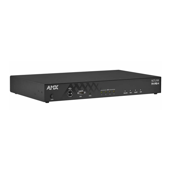
TPI-PRO-4 Front and Rear Components Power switch/LED 2 USB (Type-A) Host Interface ports (Configuration) port VIDEO/VGA Inputs 1-4 FIG. 3 TPI-PRO-4 TPI-PRO-2 Front and Rear Components Power switch/LED 2 USB (Type-A) Host Interface ports (Configuration) port VIDEO/VGA Inputs 1-2 FIG. 4 TPI-PRO-2... -
Page 9: Tpi-Pro Specifications
The following table lists the specifications for the TPI-PRO-4 and TPI-PRO-2. Note that the primary difference between the TPI-PRO-4 and TPI-PRO-2 is in the number of inputs. In terms of functionality and specifications, they are otherwise identical. Therefore, the specifications listed below apply to both versions, unless specifically noted. -
Page 10: Tpi-Pro
Power connector Yellow LEDs indicate a valid input signal on each source input (1-4 on the TPI-PRO-4, 1-2 on the TPI-PRO-2). Four white buttons provide access to the following configuration options: • RESOLUTION: Opens a screen used to select the TPI-PRO output video signal resolution, ranging from 640 x 480@60Hz to 1920 x 1200@60Hz. - Page 11 For an updated list of available serial touch input drivers that are selectable by using the TOUCH button on the front panel of the TPI-PRO, visit www.amx.com. Refer to the List of Available Pixel Display and Refresh Rates section on page 140 for a more detailed list of Touch Monitors that have been tested with the TPI-Pro.
- Page 12 Overview TPI-PRO Specifications (Cont.) Other AMX Equipment: • PSN6.5: Power Supply with 3.5 mm mini-Phoenix connector (FG423-40) • CC-HD15M-HD15M – HD-15 Male to HD-15 Male, 6’ cable (FG10-2170-01) • CC-HD15M-RCAM3 – HD-15 to 3x Male RCA connectors for component or composite sources (FG10-2170-03) •...
-
Page 13: Installation
Installation Overview The TPI-PRO comes included with rack ears that can be rotated 90° in any direction to accommodate several different mounting options, including tabletop, under/over the table, and vertical wall mounting. Rotate the mounting brackets to mount the TPI-PRO on top of a flat surface, under-table, or vertically. Mounting the TPI-PRO into an 19"... -
Page 14: Ventilation
Installation Ventilation ALWAYS ensure that the rack enclosure is adequately ventilated. The maximum operating ambient temperature is 40°C. Sufficient airflow must be achieved (by convection or forced-air cooling) to satisfy the ventilation requirements of all the items of equipment installed within the rack. Never restrict the airflow through the device’s fan or vents. - Page 15 Installation TPI-PRO Total Presentation Interface - Pro Edition...
- Page 16 Installation TPI-PRO Total Presentation Interface - Pro Edition...
-
Page 17: Wiring And Device Connections
Note that the rear panel connectors on both versions of the TPI-PRO are identical, with the exception of the number of HD-15 inputs for VIDEO/VGA (four on the TPI-PRO-4, two on the TPI-PRO-2), and SOURCE KEYBOARD/MOUSE USB ports (four on the TPI-PRO-4, two on the TPI-PRO-2). -
Page 18: System Diagrams
Wiring and Device Connections System Diagrams The following System Diagrams illustrate the most common applications for the TPI-PRO. For detailed pinout descriptions for each connector on the TPI-PRO, refer to the Connector Details and Pinout Configurations section on page 17. Example 1 (TOUCH INPUT) The example below displays a typical installation using a touch panel to display output from a video source (in this case, a PC.) -
Page 19: Example 2 (Mouse Pass-Thru Control)
6. Cycle power the unit. Cycle powering the unit allows it to detect the new configuration. Example 2 (Mouse Pass-Thru Control) The example below displays a typical installation for using a touch panel for mouse pass-thru control. Signal video feed from the computer to the monitor through the... - Page 20 Using a USB hub may cause functionality issues with all USB ports on the TPI-PRO. AMX recommends you do not use a USB hub to connect multiple USB devices to the TPI-PRO. USB 2.0 support is required for all USB devices.
-
Page 21: Example 3 (Using A Touch Panel For Mouse / Touch Pass-Thru Control)
10. Use the CRT’s video adjust buttons to align the incoming video signal to fit into the available screen area. Initially positioning the TPI-PRO incoming video can reduce any later adjustments of the video through the RGB Setup page (H-position, V-position, H-size, etc.) Example 3 (Using a Touch Panel for Mouse / Touch Pass-Thru Control) The example below displays a typical installation for using a touch panel for mouse and touch pass-thru control. - Page 22 Wiring and Device Connections Follow these steps to configure the TPI-PRO to use a touch panel for touch and mouse pass-thru control: 1. Discharge any acquired static electricity by touching a grounded metal object. 2. Disconnect any incoming power connector from the rear of the TPI-PRO. 3.
-
Page 23: Connector Details And Pinout Configurations
The Video/VGA Input connectors are used for source input devices (4 on the TPI-PRO-4, 2 on the TPI-PRO-2). Each connector supports VGA graphics, S-video, composite video, and component video. The TPI-PRO routes the video from the connected input devices to any connected output devices. - Page 24 Wiring and Device Connections The following tables list the VGA OUT HD-15 connector pinouts. VGA OUT HD-15 Connector Pinouts Signal Function Red signals Green Green signals Blue Blue signals Sense 2 Monitor ID bit 2 Signal Ground RAGND Red analog ground GAGND Green analog ground BAGND Blue analog ground Not used...
- Page 25 The following table lists the pinout configuration for HD-15 connector to Component (RGB) connectors: VGA IN to Component (RGB) Pinouts VGA Pin VGA Signal Green Blue Sense 2 RAGND GAGND BAGND SAGND Sense 0 Sense 1 HSYNC VSYNC Sense 3 The following table lists the pinout configuration for HD-15 connector to Composite (BNC) connectors: VGA IN to Composite Pinouts Signal...
-
Page 26: Source Keyboard/Mouse (Usb-Type B) Ports
SOURCE KEYBOARD/MOUSE (USB-Type B) Ports You can connect up to four USB Type-B Host PC connections for TOUCH, Mouse and Keyboard pass-through to the PC (two on the TPI-PRO-2, four on the TPI-PRO-4) via the SOURCE KEYBOARD/ MOUSE USB connectors. -
Page 27: Touch Input (Db9) Port
TOUCH INPUT (DB9) Port FIG. 14 TOUCH INPUT (DB9) Port The RS-232 (DB9) 9-pin serial port provides connectivity to a pointer device (i.e. touch screen) that requires a serial connection. The following table lists the RS-232 connector pinouts. (DB9) RS-232 Connector Pinouts Signal Function Not used Receive data... -
Page 28: Ethernet (Rj-45) Port
Wiring and Device Connections ETHERNET (RJ-45) Port FIG. 15 ETHERNET (RJ-45) Port The RJ-45 port provides 10/100 Mbps communication communicates with the NetLinx Master (via ICSP protocol over Ethernet). The Ethernet port automatically negotiates the connection speed (10 Mbps or 100 Mbps), and whether to use half duplex or full duplex mode. This communication is reflected via the front ICSP LED. -
Page 29: Power (2-Pin Captive Wire) Connector
Power (2-Pin Captive Wire) Connector FIG. 18 Power (2-Pin Captive Wire) Connector The TPI-PRO requires a 12 VDC-compliant power supply to provide power to the TPI-PRO via the 2-pin 3.5 mm mini-Phoenix PWR connector. The incoming PWR and GND wires from the power supply must be connected to the corresponding locations within the PWR connector. - Page 30 Wiring and Device Connections TPI-PRO Total Presentation Interface - Pro Edition...
-
Page 31: Tpi-Pro And Panel Interface Setup
TPI-PRO is receiving power, loading firmware, and preparing to display the default touch panel page. When the panel is ready, the AMX Splash Screen is replaced by the Initial Panel Setup page. TPI-PRO Startup Routine and Initial Panel Response 1. -
Page 32: Setting The Output Resolution On The Tpi-Pro
TPI-PRO and Panel Interface Setup Setting the Output Resolution on the TPI-PRO To correct the problem of an OUT OF RANGE message, the TPI-PRO output resolution must be set to match the same output pixel resolution and refresh rate set on the connected panel/monitor. The default TPI-PRO output resolution is 1280 x 1024@60Hz. -
Page 33: Setting The Touch Drivers
2. Press the front panel TOUCH button to cycle through a series of available touch input drivers. For a list of current compatible touch drivers, visit www.amx.com. Verify that the selected touch driver matches the connected touch panel or monitor. Refer to the List of Available Pixel Display and Refresh Rates section on page 140 for a comprehensive list of Touch Monitors that have been tested with the TPI-PRO. -
Page 34: Calibrating The Tpi-Pro Using A Usb Input
5. After the "Calibration Successful." message appears, press anywhere to return to the Setup page. If the calibration fails, attempt to calibrate again. If unsuccessful, call AMX Tech Support. It is recommended that you calibrate the TPI-PRO before its initial use, after completing a firmware download, and after switching touch input drivers (and touch devices.) - Page 35 6. Press the Protected Setup button (located on the lower-left of the panel page) to open the Protected Setup page. 7. Enter 1988 into the Keypad’s password field and press Done when finished. 8. Press the on-screen Reboot button to cycle power to the TPI-PRO and incorporate the new settings. The touch monitor goes blank for a few seconds during the reboot process.
- Page 36 TPI-PRO and Panel Interface Setup TPI-PRO Total Presentation Interface - Pro Edition...
-
Page 37: Configuring Communication
Configuring Communication Communication between the TPI-PRO and the NetLinx Master consists of using an Ethernet connection (DHCP or Static IP). If you are currently using a static IP Address, continue with the IP Settings section - Configuring a Static IP Address over Ethernet section on page 33. Before commencing, verify you are using the latest NetLinx Master firmware. - Page 38 Configuring Communication FIG. 23 Protected Setup page with Keypad 7. Use the Baud Rate Up/Down arrows to cycle through the available baud rates for TPI-PRO serial communication to the connected PC. The default is 38400. Before continuing, open NetLinx Studio. This program assists in developing a System Number, Master IP/URL, and Master Port number.
-
Page 39: Configuring A Wired Ethernet Connection
Configuring a Wired Ethernet Connection It is necessary to tell the panel with which Master it should be communicating. "Pointing to a Master" is configured via the System Connection page where you configure the IP Address, System Number, and Username/Password information assigned to the target Master. Until you configure these parameters, your Connection Status icon remains red, indicating there is no current connection to a Master. -
Page 40: Step 2: Choosing A Master Connection Mode Setting
Configuring Communication 10. Press the Domain field to open a keyboard, enter the resolvable domain address (this is provided by your System Administrator and equates to a unique Internet name for the TPI-PRO.) Press Done when complete. 11. Press the Back button to return to the Protected Setup page. 12. -
Page 41: Master Connection Section - Netlinx Master Ethernet Ip Address - Url Mode
4. Connect the terminal end of the PSN power cable to the 12 VDC power connector on the rear of the TPI-PRO. 5. Verify the green Ethernet LED on the rear Ethernet port on both the Master and TPI-PRO are illuminated, indicating a proper connection. -
Page 42: Master Connection Section - Netlinx Master Ethernet Ip Address - Listen Mode
Configuring Communication 7. Press the on-screen Reboot button to both save any changes and restart the TPI-PRO. Master Connection section - NetLinx Master Ethernet IP Address - Listen Mode In this mode, you must add the TPI-PRO IP address into the URL List of the Master (using NetLinx Studio). -
Page 43: Master Connection Section - Netlinx Master Ethernet Ip Address - Auto Mode
Master Connection section - NetLinx Master Ethernet IP Address - Auto Mode In this mode, enter the System Number of the NetLinx Master. This mode instructs the TPI-PRO to search for a Master that uses the same System Number (assigned within the Master Connection section) and resides on the same Subnet as the TPI-PRO. -
Page 44: Master Connection Section - Netlinx Master Ethernet Ip Address - Url (Udp) Mode
Refer to the G4 Web Control Page section on page 61 for more detailed information. Verify your NetLinx Master (ME260/64 or NI-Series) has been installed with the latest firmware KIT file from www.amx.com. Refer to your NetLinx Master Instruction Manual for more detailed information on the use of the new web-based NetLinx Security. - Page 45 5. Press the G4 Web Control button to open the G4 Web Control page (FIG. 27). FIG. 27 G4 Web Control page 6. Press the Enable/Enabled button until it toggles to Enabled (light blue color). 7. The Network Interface Select field is read-only for the TPI-PRO and uses Wired as the default method of communication to the web.
-
Page 46: Using Your Netlinx Master To Control The Unit
If the Master has been previously configured for secured communication, click OK to accept the AMX SSL certificate (if SSL is enabled) and then enter a valid username and password into the fields within the Login dialog. 4. Click OK to enter the information and proceed to the Master’s Manage WebControl Connections window. - Page 47 7. Click on the G4 panel name link associated with the target panel. A secondary web browser window then appears on the screen (FIG. 29). The G4 Web Control application is sent by the TPI-PRO to the computer that is used for communication.
- Page 48 Configuring Communication The secondary window becomes populated with the same G4 page being displayed on the target G4 panel. A small circle appears within the on-screen G4 panel page and corresponds to the location of the mouse cursor. A left-mouse click on the computer-displayed panel page equates to an actual touch on the target G4 panel page.
-
Page 49: Upgrading Tpi-Pro Firmware
NetLinx Master instruction manual to use an address. Note the IP address and gateway information. 2. Launch NetLinx Studio 2 (default location is Start > Programs > AMX Control Disc > NetLinx Studio 2 > NetLinx Studio 2). - Page 50 Upgrading TPI-PRO Firmware FIG. 31 Assigning Communication Settings and TCP/IP Settings 4. Click the Communications Settings button to open the Communications Settings dialog box. 5. Click on the NetLinx Master option button in the Platform Selection section to indicate that you are working with a NetLinx Master (such as the NXC-ME260/64 or NI-Series of Integrated Controllers).
-
Page 51: Step 2: Prepare The Tpi-Pro For Communication Via An Ip Address
1. Press the Mode field until the choice cycles to URL. By selecting URL, the System Number field becomes read-only (grey) because the panel pulls this value directly from the communicating target Master (virtual or not). A virtual Master system value can be set within the active AMX software applications such as: NetLinx Studio, TPD4, or IREdit. - Page 52 Upgrading TPI-PRO Firmware 7. Select Tools > Firmware Transfers > Send to NetLinx Device from the Main menu to open the Send to NetLinx Device dialog box (FIG. 33). Verify the TPI-PRO’s System and Device number values match those values listed within the System folder in the OnLine Tree tab of the Workspace window.
-
Page 53: Firmware Pages And Descriptions
Firmware Pages and Descriptions This section describes each G4 firmware page and their specific functional elements. The TPI-PRO is a G4 device that utilizes specific G4 pages. Setup Navigation Buttons The G4 Setup Navigation Buttons (FIG. 34) appear on the left of the panel screen when the Setup page is currently active. -
Page 54: Setup Page
• The TPI-PRO-4 can use any combination of up to four (4) source inputs. The TPI-PRO-2 can use any combination of up to two (2) source inputs. • Refer to the Video Settings Page section on page 54 for more detailed information. - Page 55 Setup Page Elements (Cont.) Connection Status Display/Panel Timeout Inactivity Page Flip Timeout TPI-PRO Total Presentation Interface - Pro Edition Displays whether the G4 device is communicating externally, the encryption status of the communicating Master, what connection type is being used (Ethernet), and of which System the unit is a part.
-
Page 56: Project Information Page
Firmware Pages and Descriptions Project Information Page The Project Information page displays the TPDesign4 (TPD4) project file properties currently loaded on the selected TPI-PRO (FIG. 36). Refer to the TPDesign4 Touch Panel Program instruction manual for more specific information on uploading TPDesign4 files to a panel. FIG. -
Page 57: Panel Information Page
Displays the type of G4 device being used. Displays the G4 firmware version being used by the G4 device. • Verify you have the latest version from www.amx.com. Displays the setup port information/value being used by the TPI-PRO. Displays the high port (port count) value for the TPI-PRO. -
Page 58: Time & Date Setting Page
Firmware Pages and Descriptions Panel Information Page Elements (Cont.) Power Up Page Start Up String Wake Up String Sleep String File System Time & Date Setting Page The Time & Date Settings page (FIG. 38) allows you to alter or set the time and date information on the NetLinx Master. -
Page 59: Audio Settings Page Elements
Time & Date Setup Page Elements (Cont.) Time Display fields Date Display fields Set Date/Time The TPI-PRO does not have an on-board clock. This page both receives and sets the time/date of the NetLinx Master. Audio Settings The Audio Settings page (FIG. 39) (accessed by pressing the Audio button on the Setup page) allows you to adjust the master volume parameters and default panel sounds on the TPI-PRO. -
Page 60: Supported Sampling Rates For Wav
Video button on the Setup page. This page contains four tabs across the top for each source input on the unit. If you are using a TPI-PRO-2, slots 3 and 4 appear greyed out. - Page 61 The elements of the Video Settings page are described in the table below: Video Settings Page Elements Back Connection Status icon Input Status Version Auto Adjust Black & White Brightness Contrast Saturation Phase H Position H Size V Position Default Settings TPI-PRO Total Presentation Interface - Pro Edition Saves the changes and returns you to the previously active touch panel page.
-
Page 62: Video Settings - Rgb Adjustment Page
Firmware Pages and Descriptions Video Settings Page Elements (Cont.) Undo Changes Save Settings Video Settings - RGB Adjustment Page The RGB Adjustment page (FIG. 41) sets the RGB properties of the incoming signal. You can access this page by pressing the incoming signal area on the Video Adjustment page as long as an RGB signal is currently displaying. -
Page 63: Adjusting The Incoming Image On The Video Adjustment Page
Adjusting the Incoming Image on the Video Adjustment Page After opening the Video Adjustment page, you can select any of the available source inputs by selecting the corresponding tab at the top of the screen. If the selected source input is receiving an image, this image is displayed in the incoming signal area. -
Page 64: Protected Setup Navigation Buttons
Firmware Pages and Descriptions Protected Setup Navigation Buttons The Protected Setup Navigation Buttons (FIG. 42) appear on the left of the screen when the Protected Setup page is currently active. FIG. 42 G4 Protected Setup Navigation Buttons These Navigation Buttons are specific to the TPI-PRO device and include the device specific elements described in the following table: G4 Protected Setup Navigation Button Elements System Settings... -
Page 65: Protected Setup Page
Protected Setup Page The Protected Setup page (FIG. 43) centers around the properties used by the TPI-PRO to communicate with the NetLinx Master. Enter the factory default password (1988) into the password keypad to access this page. FIG. 43 Protected Setup page The elements of the Protected Setup page are described in the table below: Protected Setup Page Elements Back... - Page 66 • The Remove User Pages button allows you remove all current TPD4 touch panel pages currently on the TPI-PRO (including the pre-installed AMX Demo pages). - Pressing this button launches a Confirmation dialog box (FIG. 44) which asks you to confirm your selection.
-
Page 67: G4 Web Control Page
G4 Web Control Page The G4 Web Control page (FIG. 46) centers around enabling and disabling both the display and control of your TPI-PRO (via the web). An external PC running a VNC client (installed during the initial communication to the G4 device) makes this possible. FIG. - Page 68 Firmware Pages and Descriptions G4 Web Control Page Elements (Cont.) G4 Web Control Settings Enable/Enabled Network Interface Select Web Control Name Web Control Password Web Control Port Max Number of Connections Current Connection Count G4 Web Control Timeout Refer to the Using G4 Web Control® to Interact with a G4 Panel section on page 38 for more detailed instructions on how to use the G4 Web Control page with the new web-based NetLinx Security application.
-
Page 69: Password Setup Page
Password Setup Page The Password Setup page (FIG. 47) centers around the properties used to assign passwords for the panel pages. FIG. 47 Password Setup page The elements of the Password Setup page are described in the table below: Password Setup Page Elements Back Connection Status icon In Panel Password Change Accesses the alphanumeric values associated to particular password sets. -
Page 70: System Settings Page
Firmware Pages and Descriptions Press and hold the front panel CALIBRATE button to access the Calibration page. Press the crosshairs to calibrate the panel and return to the last open firmware page. System Settings Page The System Settings page (FIG. 49) sets the DNS Address information with its corresponding IP communication parameters, NetLinx Master communication settings, and reads the device number assigned to the G4 device. - Page 71 Sets the speed of the Ethernet connection to the TPI-PRO. • Choices are: Auto, 10 Half Duplex, 10 Full Duplex, 100 Half Duplex, or 100 Full Duplex. Displays a read-only field that is factory set by AMX for the built-in Ethernet interface. Sets the NetLinx Master communication values: Sets the NetLinx Master to communicate to the TPI-PRO via Ethernet.
-
Page 72: Cache Page
Firmware Pages and Descriptions Cache Page The Cache page (FIG. 50) configures the allocation of memory for image caching. The G4 graphics engine caches images to decrease load time of previously viewed images. RAM caching is always enabled, and images (both static and dynamic) are stored in the RAM cache as they are viewed. The size of RAM cache is automatically configured to take into account available memory versus memory that may be needed by the panel later. - Page 73 The elements of the Cache page are described in the following table: Image Caching Page Elements Back Connection Status icon Image Cache Settings Flash Cache Size Flash/RAM Cache Expires Enable Clear Cache Image Cache Status RAM Max Size RAM Current Size RAM Hit Rate Items in Cache (RAM) Flash Current Size...
-
Page 74: Setting The Image Cache
Firmware Pages and Descriptions Setting the image cache In the Protected Setup page: 1. Press the Other Settings button to open an options slide bar. 2. Press the Cache button in the slide bar. The Cache page opens. 3. Set the cache expiration in the field Flash/RAM Cache Expires. The Up and Down arrows increment through the available time frames. -
Page 75: Checking The Panel Connection Logs
The elements of the Panel Logs page are described in the following table: Panel Logs Page Back Connection Status icon Connection Logs Clear Refresh Page Checking the Panel Connection Logs 1. Press the Tools button in the Protected Setup Navigation Buttons section. This opens the Tools menu. -
Page 76: Panel Statistics Page
Firmware Pages and Descriptions Panel Statistics Page The options on the Panel Statistics page allow you to track the connection status for the panel. The Panel Statistics page tracks ICSP messages, Blink messages, Ethernet connection statistics, and Wireless connection statistics (FIG. 52). FIG. -
Page 77: Checking The Panel Statistics
Checking the Panel Statistics 1. Press the Tools button in the Protected Setup Navigation Buttons section. This opens the Tools menu. 2. Within the Tools menu, press the Panel Statistics button. All connection statistics are contained on this page, e.g., Received, Processed, and Dropped ICSP Messages. Refreshing the Panel Statistics 1. -
Page 78: Connection Utility Page
Firmware Pages and Descriptions Connection Utility Page The options on the Connection Utility page allows you to view query and response statistics for your connection. FIG. 53 Connection Utility page The elements of the Connection Utility page are described in the following table: Connection Utility Page Close Connection Status icon... -
Page 79: Using The Connection Utility
Connection Utility Page (Cont.) Signal Strength Connection Statistics Query Messages Sent Responses Received Responses Missed Using the Connection Utility 1. Press the Tools button in the Protected Setup Navigation Buttons section. This opens the Tools menu. 2. Within the Tools menu, press the Connection Utility button. This launches the Connection Utility page. - Page 80 Firmware Pages and Descriptions TPI-PRO Total Presentation Interface - Pro Edition...
-
Page 81: Programming
Programming You can program a touch panel using the commands in this section to perform a wide variety of operations using Send_Commands and variable text commands. Refer to the NetLinx Programming Language instruction manual for complete information. Verify you are using the latest NetLinx Master firmware. Verify the NetLinx Studio program being used is version 2.4 or higher and TPD4 is version 2.8 or higher. - Page 82 Programming Page Commands (Cont.) Syntax: @CPG Clear all popup pages from Variable: specified popup group. Example: Clears all popup pages from the popup group ’Group1’. @DPG Syntax: Delete a specific popup page from Variable: specified popup group if it exists. Example: Deletes the popup page ’Popup1’...
- Page 83 Page Commands (Cont.) Syntax: @PHT Set the hide effect "'@PHT-<popup page name>;<hide effect time>'" time for the Variable: specified popup popup page name = 1 - 50 ASCII characters. Name of the page on which the popup is page. displayed. hide effect time = Given in 1/10ths of a second.
- Page 84 Programming Page Commands (Cont.) Kill refers to the deactivating (Off) of a popup window from all pages. If the pop-up page is @PPK part of a group, the whole group is deactivated. This command works in the same way as Kill a specific the 'Clear Group' command in TPDesign4.
- Page 85 Page Commands (Cont.) If timeout is empty, popup page will clear the timeout. @PPT Set a specific Syntax: popup page to "'@PPT-<popup page name>;<timeout>'" timeout within a Variable: specified time. popup page name = 1 - 50 ASCII characters. Name of the popup page. timeout = Timeout duration in 1/10ths of a second.
- Page 86 Programming Page Commands (Cont.) Flips to a page with a specified page name. If the page is currently active, it will not redraw PAGE the page. Flip to a specified page. Syntax: Variable: Example: Flips to page1. PPOF If the page name is empty, the current page is used (see example 2). If the popup page is part of a group, the whole group is deactivated.
-
Page 87: Programming Numbers
Page Commands (Cont.) If the page name is empty, the current page is used (see example 2). If the popup page is PPON already On, do not re-draw it. This command works in the same way as the ’Show Popup’ Activate a specific command in TPDesign4. - Page 88 Programming RGB Values for all 88 Basic Colors (Cont.) Index No. Name Lime Medium Lime Dark Lime Very Dark Lime Very Light Green Light Green Green Medium Green Dark Green Very Dark Green Very Light Mint Light Mint Mint Medium Mint Dark Mint Very Dark Mint Very Light Cyan...
-
Page 89: Font Styles And Id Numbers
Font type Courier New Courier New Courier New Courier New Courier New Courier New Courier New Courier New AMX Bold AMX Bold AMX Bold TPI-PRO Total Presentation Interface - Pro Edition Green Size Font ID # Font type Arial Arial... -
Page 90: Border Styles
The TPDesign4 Touch Panel Design program has pre-set border styles that are user selectable. TPD4 border styles can ONLY be changed by using the name. TPD4 Border Styles by Name Border styles None AMX Elite -L AMX Elite -M AMX Elite -S Bevel -L Bevel -M... - Page 91 TPD4 Border Styles by Name (Cont.) Diamond 15 Diamond 25 Diamond 35 Diamond 45 Menu Left Rounded 105 Menu Left Rounded 115 Menu Left Rounded 125 Menu Left Rounded 135 Menu Left Rounded 145 Menu Left Rounded 155 Menu Left Rounded 165 Menu Left Rounded 175 Menu Left Rounded 185 Menu Left Rounded 195...
-
Page 92: Button Commands
Programming "^" Button Commands These Button Commands are not case sensitive. All commands that begin with "^" have the capability of assigning a variable text address range and button state range. A device must first be defined in the NetLinx programming language with values for the Device: Port : System (in all programming examples - Panel is used in place of these values). - Page 93 "^" Button Commands (Cont.) Syntax: ^BAT Append "'^BAT-<vt addr range>,<button states range>,<new text>'" non-unicode text. Variable: variable text address range = 1 - 4000. button states range = 1 - 256 for multi-state buttons (0 = All states, for General buttons 1 = Off state and 2 = On state).
- Page 94 Programming "^" Button Commands (Cont.) This command works only if the specified fill color is not the same as the current color. ^BCF Set the fill color to Note: Color can be assigned by color name (without spaces), number or R,G,B value the specified (RRGGBB or RRGGBBAA).
- Page 95 "^" Button Commands (Cont.) Determines what order each layer of the button is drawn. ^BDO Set the button Syntax: draw order. "'^BDO-<vt addr range>,<button states range>,<1-5><1-5><1-5><1- 5><1-5>'" Variable: variable text address range = 1 - 4000. button states range = 1 - 256 for multi-state buttons (0 = All states, for General buttons 1 = Off state and 2 = On state).
- Page 96 Programming "^" Button Commands (Cont.) Syntax: ^BIM Set the input mask for the Variable: specified address. Example: Sets the input mask to ten ’A’ characters, that are required, to either a letter or digit (entry is required). ^BLN The maximum number of lines to remove is 240. A value of 0 will display the incoming video signal unaffected.
- Page 97 "^" Button Commands (Cont.) Note that the source is a single button state. Each state must be copied as a separate ^BMC command. The <codes> section represents what attributes will be copied. All codes are 2 Button copy character pairs that can be separated by comma, space, percent or just ran together. command.
- Page 98 Programming "^" Button Commands (Cont.) Syntax: ^BMF Set any/all button parameters by Variables: sending embedded codes and data. "'^BMF-<vt addr range>,<button states range>,<data>'" variable text address char array = 1 - 4000. button states range = 1 - 256 for multi-state buttons (0 = All states, for General buttons 1 = Off state and 2 = On state).
- Page 99 "^" Button Commands (Cont.) For some of these commands and values, refer to the RGB Values for all 88 Basic ^BMF (Cont.) Colors table on page 81. ’%CF<on fill color>’ = Set Fill Color. ’%CB<on border color>’ = Set Border Color. ’%CT<on text color>’...
- Page 100 Programming "^" Button Commands (Cont.) Mask image is used to crop a borderless button to a non-square shape. This is typically ^BMI used with a bitmap. Set the button mask image. Syntax: Variable: Example: Sets the button with variable text 530 ON/OFF state mask image to 'newmac.png'. ^BML If this value is set to zero (0) there is no max length.
- Page 101 ^BNN Syntax: Set the TakeNote "'^BNN-<vt addr range>,<network name>'" network name for Variable: the specified variable text address range = 1 - 4000. Addresses. network name = Use a valid IP Address. Example: SEND_COMMAND Panel,"'^BNN-973,192.168.169.99'" Sets the TakeNote button network name to 192.168.169.99. ^BNT Syntax: Set the TakeNote...
- Page 102 Sets the border by number (#10) to those buttons with the variable text range of 500-504 & 510-515. Sets the border by name (AMX Elite) to those buttons with the variable text range of 500-504 & 510-515. The border style is available through the TPDesign4 border-style drop-down list. Refer to the TPD4 Border Styles by Name table on page 84 for more information.
- Page 103 ^BRD This command works only if the specified border is not the same as the current border. The border names are available through the TPDesign4 border-name drop-down list. Set the border of a button state/ Syntax: states. "'^BRD-<vt addr range>,<button states range>,<border name>'" Variable: variable text address range = 1 - 4000.
- Page 104 Programming ^BVL Syntax: Log-On/Log-Off the computer Variable: control connection. Example: Logs-off the computer control connection of the button. ^BVN Syntax: Set the network name for the Variable: specified address. Example: Sets the network name to ’191.191.191.191’ for the specific control button. ^BVP Syntax: Set the network...
- Page 105 ^CPF Syntax: Clear all page flips "'^CPF-<vt addr range>'" from a button. Variable: variable text address range = 1 - 4000. Example: SEND_COMMAND Panel,"'^CPF-500'" Clears all page flips from the button. ^DPF Syntax: Delete page flips "'^DFP-<vt addr range>,<actions>,<page name>'" from button if it Variable: already exists.
- Page 106 Programming "^" Button Commands (Cont.) Syntax: ^GDI Change the bargraph drag Variable: increment. Example: Sets the bargraph with variable text 7 to a drag increment of 128. ^GIV Parameters 1, 2, and 3 will cause a bargraph or slider to be inverted regardless of orientation.
- Page 107 "^" Button Commands (Cont.) Syntax: ^GRD Change the "'^GRD-<vt addr range>,<bargraph ramp down time>'" bargraph Variable: ramp-down time variable text address range = 1 - 4000. in 1/10th of a bargraph ramp down time = in 1/10th of a second intervals. second.
- Page 108 Programming "^" Button Commands (Cont.) Syntax: ^ICO Set the icon to a button. Variable: Example: Sets the icon for On and Off states for buttons with variable text ranges of 500-504 & 510-515. ^JSB The alignment of 0 is followed by ',<left>,<top>'. The left and top coordinates are relative to the upper left corner of the button.
- Page 109 "^" Button Commands (Cont.) The alignment of 0 is followed by ',<left>,<top>'. The left and top coordinates are relative ^JST to the upper left corner of the button. Set text alignment using a numeric Syntax: keypad layout for "'^JST-<vt addr range>,<button states range>,<new text those buttons with alignment>'"...
- Page 110 Programming "^" Button Commands (Cont.) The Text Effect is specified by name and can be found in TPD4. You can also assign the ^TEC color by name or RGB value (RRGGBB or RRGGBBAA). Set the text effect color for the Syntax: specified addresses/states...
- Page 111 "^" Button Commands (Cont.) For the ^UNI command (%UN and ^BMF command), the Unicode text is sent as ^UNI ASCII-HEX nibbles. Set Unicode text. Syntax: "'^UNI-<vt addr range>,<button states range>,<unicode text>'" Variable: variable text address range = 1 - 4000. button states range = 1 - 256 for multi-state buttons (0 = All states, for General buttons 1 = Off state and 2 = On state).
-
Page 112: Text Effect Names
Programming Text Effect Names The following is a listing of text effects names. This list is associated with the ^TEF command on page 104. Text Effect Names • Glow -S • Glow -M • Glow -L • Glow -X • Outline -S •... -
Page 113: Button Query Commands
Button Query Commands Button Query commands reply back with a custom event. There will be one custom event for each button/state combination. Each query is assigned a unique custom event type. The following example is for debug purposes only: NetLinx Example: CUSTOM_EVENT[device, Address, Custom event type] DEFINE_EVENT CUSTOM_EVENT[TP,529,1001] CUSTOM_EVENT[TP,529,1002]... - Page 114 Programming These fields are populated differently for each query command. The text length (String Encode) field is not used in any command. Button Query Commands ?BCB Syntax: Get the current border color. Variable: Example: Gets the button 'OFF state' border color. information. The result sent to the Master would be: "'?BCB-<vt addr range>,<button states range>'"...
- Page 115 Button Query Commands (Cont.) Syntax: ?BCF Get the current fill "'?BCF-<vt addr range>,<button states range>'" color. Variable: variable text address range = 1 - 4000. button states range = 1 - 256 for multi-state buttons (0 = All states, for General buttons 1 = Off state and 2 = On state).
- Page 116 Programming Button Query Commands (Cont.) Syntax: ?BMP Get the current bitmap name. Variable: Example: Gets the button 'OFF state' bitmap information. The result sent to the Master would be: ?BOP Syntax: Get the overall button opacity. Variable: Example: Gets the button 'OFF state' opacity information. The result sent to the Master would be: "'?BMP-<vt addr range>,<button states range>'"...
- Page 117 Button Query Commands (Cont.) Syntax: ?BRD Get the current "'?BRD-<vt addr range>,<button states range>'" border name. Variable: variable text address range = 1 - 4000. button states range = 1 - 256 for multi-state buttons (0 = All states, for General buttons 1 = Off state and 2 = On state).
- Page 118 Programming Button Query Commands (Cont.) Syntax: ?FON Get the current font index. Variable: Example: Gets the button 'OFF state' font type index information. The result sent to the Master would be: ?ICO Syntax: Get the current icon index. Variable: Example: Gets the button 'OFF state' icon index information.
- Page 119 Button Query Commands (Cont.) Syntax: ?JSB Get the current "'?JSB-<vt addr range>,<button states range>'" bitmap Variable: justification. variable text address range = 1 - 4000. button states range = 1 - 256 for multi-state buttons (0 = All states, for General buttons 1 = Off state and 2 = On state).
- Page 120 Programming Button Query Commands (Cont.) Syntax: ?JST Get the current text justification. Variable: Example: Gets the button 'OFF state' text justification information. The result sent to the Master would be: ?TEC Syntax: Get the current text effect color. Variable: Example: Gets the button 'OFF state' text effect color information.
- Page 121 Button Query Commands (Cont.) Syntax: ?TEF Get the current "'?TEF-<vt addr range>,<button states range>'" text effect name. Variable: variable text address range = 1 - 4000. button states range = 1 - 256 for multi-state buttons (0 = All states, for General buttons 1 = Off state and 2 = On state).
-
Page 122: Panel Runtime Operations
Programming Panel Runtime Operations Serial Commands are used in the AxcessX Terminal Emulator mode. These commands are not case sensitive. Panel Runtime Operation Commands ABEEP Syntax: Output a single beep even if beep Example: is Off. Outputs a beep of duration 1 beep even if beep is Off. ADBEEP Syntax: Output a double... - Page 123 Panel Runtime Operation Commands (Cont.) Keypad string is set to null on power up and is stored until power is lost. The Prompt Text @AKP is optional. Pop up the keypad icon and Syntax: initialize the text "'@AKP-<initial text>;<prompt text>'" string to that Variables: specified.
- Page 124 Programming Panel Runtime Operation Commands (Cont.) Pops up the keypad icon and initializes the text string to that specified. Keypad displays a PKEYP '*' instead of the numbers typed. The Prompt Text is optional. Present a private keypad. Syntax: Variables: Example: Pops up the Keypad and initializes the text string '123456789' in '*'.
- Page 125 Panel Runtime Operation Commands (Cont.) Pops up the keypad icon and initializes the text string to that specified. The Prompt Text is @TKP optional. Present a telephone keypad. Syntax: "'@TKP-<initial text>;<prompt text>'" Variables: initial text = 1 - 50 ASCII characters. prompt text = 1 - 50 ASCII characters.
-
Page 126: Input Commands
Programming Input Commands These Send Commands are not case sensitive. Input Commands ^CAL Syntax: Put panel in calibration mode. Example: Puts the panel in calibration mode. Sets the USB port pass-thru, including mouse, keyboard and touch. 0 means pass data to ^PPS G4 app. -
Page 127: Embedded Codes
Input Commands (Cont.) Selects which of the 2 outputs display G4 graphics. ^TPO Sets the display Syntax: for G4 graphics. SEND_COMMAND <DEV>,"'^TPO-<Output Value>'" Variable: Output Value: Note: Any G4 graphics that appear over a Video Window when the ^TPO Command is used to turn off G4 graphics on an output may leave a “hole”... -
Page 128: Panel Setup Commands
Programming Embedded Codes (Cont.) Decimal numbers Hexidecimal values Panel Setup Commands These commands are not case sensitive. Panel Setup Commands ^MUT Syntax: Set the panel mute state. Variable: Example: Sets the panel’s master volume to mute. Virtual keystroke ($8B) ($8C) ($8D) ($8E) ($8F) - Page 129 Panel Setup Commands (Cont.) @PWD sets the level 1 password only. @PWD Set the page flip Syntax: password. "'@PWD-<page flip password>'" Variables: page flip password = 1 - 50 ASCII characters. Example: SEND COMMAND Panel,"'@PWD-Main'" Sets the page flip password to 'Main'. ^PWD Password level is required and must be 1 - 4.
-
Page 130: Dynamic Image Commands
Programming Dynamic Image Commands The following is a listing and descriptions of Dynamic Image Commands. Dynamic Image Commands ^BBR Syntax: Set the bitmap of a button to use a Variable: particular resource. Example: Sets the resource name of the button to ’Sports_Image’. ^RFR Syntax: Force a refresh for... - Page 131 Test_file%Ftest.jpg'" Adds a new resource. The resource name is ’New Image’, %P (protocol) is an HTTP, %H (host name) is AMX.COM, %A (file path) is Lab/Test file, and %F (file name) is test.jpg. TPI-PRO Total Presentation Interface - Pro Edition...
-
Page 132: Listboxes
Programming Dynamic Image Commands (Cont.) Syntax: ^RSR Change the refresh rate for a Variable: given resource. Example: Sets the refresh rate to 5 seconds for the given resource (’Sports_Image’). Listboxes Listboxes provide flexibility to remote pages once constrained by physical display areas. Both static and dynamic tables can display multiple devices and items when used with proper navigation tools. -
Page 133: List Box Commands
List Box Commands The TPI-PRO supports the following Data List Box Commands. List Box Commands Data List Commands ^LDN Creates a new data list. Unique list addresses and names are handled programmatically. ^LDA Adds a new row to an existing data list. - Page 134 Programming List Box Commands (Cont.) Data List Commands ^LDR Removes a row from an existing data list ^LDC Clears all rows in a given list ^LDD Deletes the data list ^LDT Sets the column type for a data list Syntax: SEND_COMMAND <DEV>,"'^LDR-<list address>,<uniflag>,<primary data>'"...
- Page 135 List Box Commands (Cont.) Data List Commands ^LDL Modifies the data in a single column field ^LVC Set the table column display order according to the order of the entered column values TPI-PRO Total Presentation Interface - Pro Edition Modifies the data in a single column field. This can be used to load a data list that has long text fields.
- Page 136 Programming List Box Commands (Cont.) List View Commands ^LVF Filter a list by setting what column to use and what string to compare ^LVL Set the data list to be displayed Filter a list by setting what column to use and what string to compare. Note that setting column to zero or data to none makes the filtered ordering the same as sorted ordering.
- Page 137 List Box Commands (Cont.) List View Commands ^LVM Display a new position ^LVO Display a data list according to a preset sort/ordering view definition. TPI-PRO Total Presentation Interface - Pro Edition Display a new position. If select is set, then select that new position. Syntax: SEND_COMMAND <DEV>,"'^LVM-<view address>,<offset>'"...
- Page 138 Programming List Box Commands (Cont.) List View Commands ^LVP Display a new position ^LVS Set the column order for sorting ^LVU Update any view currently looking at this list Display a new position. If the select option is set, then select that position. Syntax: SEND_COMMAND <DEV>,"'^LVP-<view address>,<index>'"...
-
Page 139: Troubleshooting
Troubleshooting This section describes the solutions to possible hardware/firmware issues that could arise during the common operation of a TPI-PRO. Troubleshooting Information Symptom Manifest.xma can not be found. An error occurs when sending a file to a G4 panel. The video pages appear blank upon TPI-PRO restart. - Page 140 "graphics hierarchy" errors, etc. indicating problems with the Compact Flash. • Panel will not boot, or gets stuck on "AMX" splash screen. • Other problems also started after downloading to a new panel or a panel with a TPD4 file that takes up a considerable amount of the available Compact Flash.
-
Page 141: Appendix
Appendix Text Formatting Codes for Bargraphs/Joysticks Text formatting codes for bargraphs provide a mechanism to allow a portion of a bargraphs text to be dynamically provided information about the current status of the level (multistate and traditional). These codes would be entered into the text field along with any other text. The following is a code list used for bargraphs: Bargraph Text Code Inputs Code... -
Page 142: Text Area Input Masking
Appendix Text Area Input Masking Text Area Input Masking can be used to limit the allowed/correct characters that are entered into a text area. For example, in working with a zip code, a user could limit the entry to a max length of only 5 characters but, with input masking, you could limit them to 5 mandatory numerical digits and 4 optional numerical digits. -
Page 143: Input Mask Ranges
Refer to the following Send Commands for more detailed information: • ^BIM page 90). • ^BMF ^BMF section on page 92). Input Mask Ranges These ranges allow a user to specify the minimum and maximum numeric value for a field. Only one range is allowed per field. -
Page 144: Input Mask Literals
Appendix Input Mask Literals To define a literal character, enter any character, other than those shown in the above table (including spaces, and symbols). A back-slash ('\') causes the character that follows it to be displayed as the literal character. For example, \A is displayed just as the letter A. To define one of the following characters as a literal character, precede that character with a back-slash. -
Page 145: Url Resources
This URL indicates that the protocol in use is http (HyperText Transport Protocol) and that the information resides on a host machine named www.amx.com. The image on that host machine is given an assignment (by the program) name of company-info-home.asp (Active Server Page). -
Page 146: List Of Available Pixel Display And Refresh Rates
List of Touch Monitors and USB Touch Drivers Tested with the TPI-PRO Refer to www.amx.com for list of latest supported serial touch monitors and USB touch monitors. The TPI-PRO KIT firmware file must be downloaded before downloading the latest TPI-PRO Drivers file (v2.3.14). The latest release of the Drivers file is incompatible with previous versions (2.2.7 and before) of the TPI-PRO firmware. - Page 147 Appendix TPI-PRO Total Presentation Interface - Pro Edition...
- Page 148 It’s Your World - Take Control™ 3000 RESEARCH DRIVE, RICHARDSON, TX 75082 USA • 800.222.0193 • 469.624.8000 • 469-624-7153 fax • 800.932.6993 technical support • www.amx.com...
Need help?
Do you have a question about the TPI-PRO-2 and is the answer not in the manual?
Questions and answers