
Related Manuals for AMX Interface Port AXB-IRS4


Summary of Contents for AMX Interface Port AXB-IRS4
- Page 1 instruction manual AXB-IRS4 IR/Serial Interface (4 Ports) A X l i n k B u s C o n t r o l l e r s...
- Page 2 This warranty extends only to products purchased directly from AMX Corporation or an Authorized AMX Dealer. AMX Corporation is not liable for any damages caused by its products or for the failure of its products to perform. This includes any lost profits, lost savings, incidental damages, or consequential damages. AMX Corporation is not liable for any claim made by a third party or by an AMX Dealer for a third party.
-
Page 3: Table Of Contents
Table of Contents Product Information ...1 Specifications ... 1 Configuration and Installation ...3 Setting the Device DIP Switch... 3 Setting the Carrier/BAUD DIP switch ... 3 Positions 1-4: Carrier signal enable/disable... 4 Position 5: RS-232/PCTouch mode ... 4 Positions 6-8: Baud rate setting ... 4 Setting the Internal Jumpers (E1 and E2) for AXlink or RS-232 Communication ... - Page 4 Table of Contents AXB-IRS4 IR/Serial Interface (4 Ports)
-
Page 5: Product Information
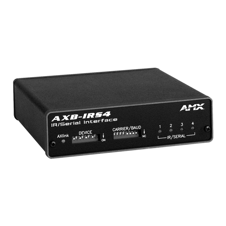
4-pin captive wire connector that supports AXlink or RS-232 data communica- tions. • If you have an AMX system, use an AXlink cable to connect to the control system. • If you have a PC, use a DB-9 or DB-25 RS-232 cable to connect to the PC. - Page 6 Product Information AXB-IRS4 Specifications (Cont.) PWR connector Battery Enclosure type Weight Dimensions Mounting options DEVICE AXlink FIG. 1 Front and rear views of the AXB-IRS4 2-pin captive wire connector connects an external 12 VDC power supply to the AXB-IRS4. An external power supply should be used when the distance between the AXB-IRS4 and control system exceeds the wiring guidelines described in the Wiring Guidelines section on page 6.
-
Page 7: Configuration And Installation
Configuration and Installation Setting the Device DIP Switch The 8-position DEVICE Make sure the device number matches the number assigned in the AXCESS software program. When you set the first device number on the assigns the next three device numbers. For example, if you set the (1+32+64=97) as shown below, the AXB-IRS4 sets ports 1 through 4 as device numbers 97, 98, 99, and 100. -
Page 8: Positions 1-4: Carrier Signal Enable/Disable
Configuration and Installation Positions 1-4: Carrier signal enable/disable DIP Switch positions 1-4 on the transmits carrier signals along with the IR equipment codes. If DIP switch positions 1 through 4 are set to the up position, the carrier signal is enabled and the AXB-IRS4 transmits IR equipment codes at device-specific signal frequencies. -
Page 9: Setting The Internal Jumpers (E1 And E2) For Axlink Or Rs-232 Communication
Setting the Internal Jumpers (E1 and E2) for AXlink or RS-232 Communication Internal jumpers are located on the circuit card inside the AXB-IRS4 enclosure. You will need a Phillips-head screwdriver to open the enclosure. Static electricity can damage electronic circuitry. Before removing the AXB-IRS4 circuit card from the enclosure, discharge any accumulated static electricity from your body and the screwdriver by touching a properly grounded metal object. -
Page 10: Wiring The Axb-Irs4
The AXB-IRS4 requires 12 VDC power to operate properly. The power can be supplied by the AMX system's AXlink cable or with an optional 12 VDC power supply. The maximum wiring distance between the control system and AXB-IRS4 is determined by power consumption, supplied voltage, and the wire gauge used for the cable. -
Page 11: Using Axlink For Data And Power
FIG. 7 AXlink and optional 12 VDC power supply wiring diagram Use the 12 VDC power supply when the distance between the AMX system and AXB-IRS4 exceeds the limits described in the Wiring Guidelines at 125 mA table on page 6. Make sure to connect only the GND wire on the AXlink/RS-232 connector when using a 12 VDC power supply. -
Page 12: Using The Axlink-To-Db-25 Connector Cable For A Pc System
Configuration and Installation FIG. 8 shows the AXlink/RS-232, DB-9, and power supply wiring diagram. For some applications, you may need to strap pins 7 (request to send) and 8 (clear to send) together depending on the PC (as shown in the illustration). 12 VDC PWR connector on AXB-CAM AXlink/RS232 connector... -
Page 13: Connecting An Ir Device
Connecting an IR device IR devices connect to the AXB-IRS4 with an IR device cable. The cables supplied with the AXB- IRS4 are designed to accommodate the IR devices in your system. IR cables have a two-pin connector on one end that plugs into the AXB-IRS4, and the other end has a device-specific interface adapter such as an IR emitter. - Page 14 Configuration and Installation Contact your AMX dealer before you replace the lithium battery and verify that they have a current copy of the AXCESS program for your AXB-IRS4. This will avoid any inadvertent loss of data or a service outage.
-
Page 15: Programming
Non-volatile data not present. Control commands are not loaded into the AXB-IRS4. Send Commands The send commands listed in the following table send software strings to the AMX system, and they are interpreted into a command and performed. The AXB-IRS4 can store up to 24 simultaneous CH, CP, SP, CTON, and CTOF send commands. - Page 16 Programming Send Commands (Cont.) Command 'CH',channel number 'CP',code 'CTOF',time 'CTON',time IROFF Description Transmit the IR pulses that select the proper channel. Enter all channel numbers below 100 as two digits. For example, enter channel 1 as 01. If the IR code for ENTER (#21) is loaded, an ENTER follows the number. If the channel is greater or equal to 100, the IR Function Number (FN) 127 is generated for the one-hundredth digit.
- Page 17 Send Commands (Cont.) Command "'SP',code" XCHM Changes the IR output pattern for the XCH command. AXB-IRS4 IR/Serial Interface (4 Ports) Description Transmit IR code pulses. Pulse time is set by the CTON and CTOF com- mands. Variable: code = 1-252 Example: SEND_COMMAND 1,"'SP',2"...
-
Page 18: Rs-232 Protocol Commands
Programming Send Commands (Cont.) Command XCH <Channel> RS-232 Protocol Commands The RS-232 protocol commands listed in the following tables send control signals from an RS-232 device to the AXB-IRS4. The following RS-232 figures are grouped together by IR output, channel pulse time, and carrier commands. -
Page 19: Rs-232 Protocol Commands (Channel Pulse Time)
RS-232 Protocol Commands (IR Output - Cont.) Command ON[Dev,Chan] SP[Dev,Chan] RS-232 Protocol Commands (Channel Pulse Time) RS-232 Protocol Commands (Channel Pulse Time) Command CTOF(Dev,Time) CTON(Dev,Time) RS-232 Protocol Commands (Carrier) RS-232 Protocol Commands (Carrier) Command CAROFF(Dev) CARON(Dev) AXB-IRS4 IR/Serial Interface (4 Ports) Description Start IR output on the designated device and channel. -
Page 20: Rs-232 Protocol Commands (Miscellaneous)
Programming RS-232 Protocol Commands (Miscellaneous) RS-232 Protocol Commands (Miscellaneous) Command Description ECHO OFF Disable the terminal character's echo function. ECHO ON Enable the terminal character's echo function. HELP Display the on-line help menu. Display the current amount of available memory. Display the current software version of the AXB-IRS4. - Page 21 Programming AXB-IRS4 IR/Serial Interface (4 Ports)
- Page 22 AMX reserves the right to alter specifications without notice at any time. brussels • dallas • los angeles • mexico city • philadelphia • shanghai • singapore • tampa • toronto* • york 3000 research drive, richardson, TX 75082 USA • 469.624.8000 • 800.222.0193 • fax 469.624.7153 • technical support 800.932.6993...
Need help?
Do you have a question about the Interface Port AXB-IRS4 and is the answer not in the manual?
Questions and answers