Extron electronics HDMI DA2 User Manual
Distribution amplifier
Hide thumbs
Also See for HDMI DA2:
- Setup manual (2 pages) ,
- User manual (34 pages) ,
- User manual (31 pages)
Table of Contents
Advertisement
Quick Links
Advertisement
Table of Contents

Related Manuals for Extron electronics HDMI DA2


Summary of Contents for Extron electronics HDMI DA2
- Page 1 User Guide HDMI ® HDMI DA2 Distribution Amplifier 68-1844-01 Rev. B 10 13...
-
Page 2: Safety Instructions
предупреждает пользователя о наличии важных инструкций For information on safety guidelines, regulatory compliances, EMI/EMF по эксплуатации и обслуживанию в руководстве, compatibility, accessibility, and related topics, see the Extron Safety and Regulatory Compliance Guide, part number 68-290-01, on the Extron прилагаемом к данному оборудованию. - Page 3 Registered Trademarks (®) AVTrac, Cable Cubby, CrossPoint, eBUS, EDID Manager, EDID Minder, Extron, Flat Field, GlobalViewer, Hideaway, Inline, IP Intercom, IP Link, Key Minder, LockIt, MediaLink, PlenumVault, PoleVault, PowerCage, PURE3, Quantum, SoundField, SpeedMount, SpeedSwitch, System Integrator, TeamWork, TouchLink, V‑Lock, VersaTools, VN‑Matrix, VoiceLift, WallVault, WindoWall, XTP, XTP Systems...
-
Page 4: Conventions Used In This Guide
SOH R Data STX Command ETB ETX Selectable items, such as menu names, menu options, buttons, tabs, and field names are written in the font shown here: From the menu, select File Click the button. Specifications Availability Product specifications are available on the Extron website, www.extron.com. -
Page 5: Table Of Contents
Connecting the Input Source ......5 Downloading HDMI DA2 Firmware ....20 Connecting the Output Displays ...... 5 Loading the Firmware to the HDMI DA2 ..21 Wiring for RS‑232 Control (Optional) ....6 Connecting to the USB Port ......7 Mounting ............25... - Page 6 HDMI DA2 • Contents...
-
Page 7: Introduction
It is fully High‑bandwidth Digital Content Protection (HDCP) compliant. The HDMI DA2 supports data rates up to 6.75 Gbps (2.25 Gbps per color) with up to 12‑bit deep color and uses the EDID Minder feature for EDID management. -
Page 8: Hdmi Da2 Application Diagram
Output Compatibility Correction — The HDMI DA2 monitors the EDID of each connected display to ensure it is compatible with the current input signal. The following adjustments are made for each output independently: Interface format: If the connected display is DVI and the input signal is HDMI, the signal is reformatted to DVI. -
Page 9: Installation
Wiring for RS-232 Control Connecting to the USB Port Installation Overview To install and set up the HDMI DA2, follow these instructions: Mount the HDMI DA2 in a suitable location (see page 25). Connect the provided 12 VDC power supply to the power connector. -
Page 10: Connecting The Power Supply
Connecting the Power Supply Connect the provided 12 VDC, 1 A power supply to the HDMI DA2 by following these instructions: WARNING: Remove power before wiring. The two power cord wires must be kept separate while the power supply is plugged in. -
Page 11: Connecting The Input Source
If necessary, EDID can be configured using SIS commands (see page 17). The HDMI DA2 monitors the EDID of each connected display to ensure it is compatible with the current input signal. The following adjustments are made for each output independently: Interface format: If the connected display is DVI and the input signal is HDMI, the signal is reformatted to DVI. -
Page 12: Wiring For Rs-232 Control (Optional)
Wire the opposite end of the cable to the provided 3‑pole captive screw plug (see figure 3): Data transmitted by the HDMI DA2 = pin 1, which plugs into the Tx (transmit) port Data received by the HDMI DA2 = pin 2, which plugs into the Rx (receive) port... -
Page 13: Connecting To The Usb Port
Connecting a PC to the HDMI DA2 Front Panel USB Port If this is the first time an HDMI DA2 has been connected to the PC, the Found New Hardware Wizard opens. The first screen offers to connect to Windows Update to search the web for the appropriate driver needed for the USB port to communicate with the distribution amplifier. - Page 14 Select to automatically connect Yes, now, and every time I connect a device to Windows Update every time the HDMI DA2 connects to this USB port. Select if you do not want to connect to Windows Update (for No, not this time example, if the driver is already on the PC).
- Page 15 The wizard appears only on the first occasion you connect the HDMI NOTE: DA2 to that USB port. The wizard reappears if you connect the HDMI DA2 to a different USB port or if you connect a different piece of equipment, requiring a different driver, to the same USB port.
-
Page 16: Operation
• permanent connection is required, the RS‑232 port should be used. When the USB Config Port is connected to the HDMI DA2 for the first time, the Found New Hardware Wizard opens to install the correct device driver (see Connecting to the USB Port on page 7). -
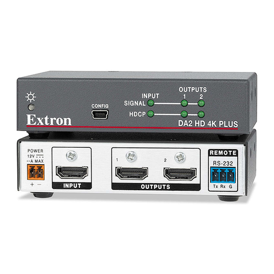
Page 17: Signal Status Leds
Signal Status LEDs Input Signal LED The input signal LED lights green when a TMDS signal is detected on the HDMI input. If the source requires HDCP encryption, this LED may light only after the HDCP has been authenticated. Output Signal LEDs There are two output signal LEDs, one for output 1 and the other for output 2. -
Page 18: Edid Minder
EDID files. This EDID is stored on an EEPROM located at the HDMI input. By default, the HDMI DA2 is configured to store EDID from the display connected to output 1 automatically. The unit reverts to this configuration after a factory reset. -
Page 19: Hdmi Da2 Memory Locations
HDMI DA2 • Operation... - Page 20 Footnotes for the EDID table (see page 13) The following footnotes apply to the EDID table on the previous page: Rate Type PC: These are primarily VESA standard computer rates, based on the most commonly used native resolutions. They are designed to be used with computer sources.
-
Page 21: Sis Commands
Command and Response Table for SIS Commands Introduction to SIS The HDMI DA2 accepts SIS commands from a host device such as a computer running the Extron DataViewer utility or other control system. The host device can be connected to the 3‑pole captive screw connector on the rear panel or to the config port on the front panel. -
Page 22: Symbols Used In This Guide
= auto (based on EDID of sink) = force 8‑bit = pass‑through — EDID memory location (see HDMI DA2 Memory Locations Table on page 13) — EDID data as 256 bytes of Hex data (text representation) — Native resolution and refresh rate (translated from Hex) for example: 1600x1200 @60Hz X&... -
Page 23: Command And Response Table For Sis Commands
Command and Response Table for SIS Commands Command ASCII Command Response Additional Description (host to unit) (unit to host) Video Mute Video mute single output Video mute output (1 or 2) Video mute all outputs Video mute all outputs Query Video mute status •... - Page 24 Command ASCII Command Response Additional Description (host to unit) (unit to host) Other Request part number 60‑997‑01 Query firmware version X&] X& = Firmware build (2 decimal places) Reset ZXXX HDMI DA2 • SIS Commands...
-
Page 25: Updating Firmware
Updating Firmware Updates to the HDMI DA2 firmware are released periodically on the Extron website. You can find which version is currently loaded on your DA using SIS commands. Compare this with the latest release on the Extron website and decide whether to update your firmware. -
Page 26: Downloading Hdmi Da2 Firmware
Firmware Figure 9. Firmware Link on the Download Tab On the Download Center screen, locate the section for the HDMI DA2 firmware (Optional) click . These notes show the issues that have been Release Notes addressed by the latest update. -
Page 27: Loading The Firmware To The Hdmi Da2
To load a new version of firmware to the switcher using Firmware Loader, connect the control PC to the HDMI DA2. You may use the front panel USB config port or the rear panel 3‑pole captive screw Remote port (see... - Page 28 HDMI DA2. If the attempted firmware upload fails for any reason, the unit reverts to the factory version. • When downloaded from the Extron website, by default the firmware is placed in a folder at C:\Program Files\Extron\ Firmware\HDMI DA2 (Windows XP) or C:\Program Files (x86)\ Extron\Firmware\HDMI DA2 (Windows 7).
- Page 29 HDMI DA2 information is added to the Devices section of the Firmware Loader window and the Add Device window closes. If you will be uploading the firmware to multiple HDMI DA2 units that are connected to your computer, do the following: Click .
- Page 30 Figure 13. Firmware Loader Screen with a HDMI DA2 Added If you want to remove a device from the Devices section, do the following: Click on the names of the devices to be deleted, to highlight them. Select from the menu.
-
Page 31: Mounting
Mounting Desktop Placement Attach the four provided rubber feet to the bottom of the HDMI DA2 and place it in any convenient location. Rack Mounting UL Guidelines for Rack Mounting The following Underwriters Laboratories (UL) guidelines are relevant to the safe installation of these products in a rack: Elevated operating ambient temperature —... -
Page 32: Extron Warranty
Extron. NOTE: If a product is defective, please call Extron and ask for an Application Engineer to receive an RA (Return Authorization) number. This will begin the repair process.
Need help?
Do you have a question about the HDMI DA2 and is the answer not in the manual?
Questions and answers