Sign In
Upload
Download
Table of Contents
Contents
Add to my manuals
Delete from my manuals
Share
URL of this page:
HTML Link:
Bookmark this page
Add
Manual will be automatically added to "My Manuals"
Print this page
×
Bookmark added
×
Added to my manuals
Manuals
Brands
Pulnix Manuals
Security Camera
TM-200
Operation manual
Pulnix TM-200 Operation Manual
Miniature ccd camera
Hide thumbs
1
2
3
4
Table Of Contents
5
6
7
8
9
10
11
12
13
14
15
16
17
18
19
20
21
22
23
24
25
26
27
28
29
30
31
32
page
of
32
Go
/
32
Contents
Table of Contents
Troubleshooting
Bookmarks
Table of Contents
Table of Contents
1 Introduction
Product Description
Features
Functional Options
Applications
System Configuration
FIGURE 1. TM-200 System Configuration
2 Installation
Getting Started
Unpacking Instructions
Components List
Accessories
Camera Setup
Connector Pin Configurations
Power Supply and Power Cable Setup
FIGURE 2. 12P-02 Interface Cable (Optional)
Attaching the Video Output
Attaching the Camera Lens
Back Focusing the Lens
Auto-Iris Lens Setup
Monitor Display Mode
Connectors and Cables
3 Operation
Modes of Operation
External Switches
Shutter Control
Field and Frame Modes
FIGURE 3. TM-200 Rear Panel
FIGURE 4. Shutter Control Settings
Integration
External Sync
Timing
FIGURE 5. Input Signals
FIGURE 6. TM-200/TM-300 Timing Chart
Interfacing to Frame Grabbers
Sync Output and Clock Output
Board Layout and Adjustment
Processor Board
Mother Board
FIGURE 7. Processor Board
4 Troubleshooting
Problems and Solutions
Symptom: no Video
Symptom: Dark Video
Symptom: Non-Synchronized Video
Information and Support Resources
5 Appendix
Specifications
Product Specifications
Physical Dimensions
Glass Specifications
C-Mount Specifications
FIGURE 8. Physical Dimensions
FIGURE 9. Camera Front End - Glass Specifications
FIGURE 10. C-Mount
FIGURE 11. Combination with "CS-Mount" Camera
Front End Detail
FIGURE 12. Front End Detail
FIGURE 13. Front End Assembly
Spectral Response
FIGURE 14. Spectral Response
Advertisement
Quick Links
1
Product Description
2
Features
3
Connector Pin Configurations
4
Specifications
5
Product Specifications
Download this manual
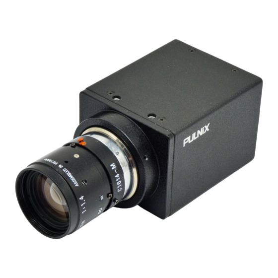
TM-200/TM-300
Miniature CCD Camera
Operation Manual
69-0047
Re v. B
Table of
Contents
Previous
Page
Next
Page
1
2
3
4
5
Advertisement
Table of Contents
Need help?
Do you have a question about the TM-200 and is the answer not in the manual?
Ask a question
Questions and answers
Related Manuals for Pulnix TM-200
Security Camera Pulnix TM-250 Operation Manual
Tm-250 miniature ccd camera (41 pages)
Security Camera Pulnix TM-5LC Operation Manual
Super miniature cylindrical ccd camera (19 pages)
Security Camera Pulnix TM-1300 Operation Manual
Progressive scan high resolution camera (44 pages)
Security Camera Pulnix TMC-6700 Series Operation Manual
Progressive scan ccd digital color camera (48 pages)
Security Camera PULNiX TM-7CN Operation Manual
Miniature ccd cameras (20 pages)
Security Camera Pulnix TM-300 Operation Manual
Miniature ccd camera (32 pages)
Security Camera Pulnix TM-1400 Series Operation Manual
Progressive scan shutter cameras (44 pages)
Security Camera Pulnix TM-75 Operation Manual
High-resolution ccd camera (39 pages)
Security Camera Pulnix TMC-7 Operation Manual
High resolution ccd color camera (14 pages)
Security Camera PULNiX TMC-7DSP Operation Manual
Color ccd camera (41 pages)
Security Camera Pulnix TMC-4200CL Operation Manual
Progressive scan camera (70 pages)
Security Camera Pulnix TM-7 Operation Manual
(15 pages)
Security Camera Pulnix TM-745E Operation & Maintenance Manual
High resolution (16 pages)
Security Camera Pulnix TM-745E Operation & Maintenance Manual
High resolution ccd camera (16 pages)
Security Camera Pulnix TMC-74 Operation & Maintenance Manual
(27 pages)
Security Camera Pulnix TM-9701 Operation & Maintenance Manual
Progressive scanning full frame shutter camera (16 pages)
This manual is also suitable for:
Tm-300
Table of Contents
Print
Rename the bookmark
Delete bookmark?
Delete from my manuals?
Login
Sign In
OR
Sign in with Facebook
Sign in with Google
Upload manual
Upload from disk
Upload from URL


Need help?
Do you have a question about the TM-200 and is the answer not in the manual?
Questions and answers