Subscribe to Our Youtube Channel
Summary of Contents for Pulnix TM-7CN
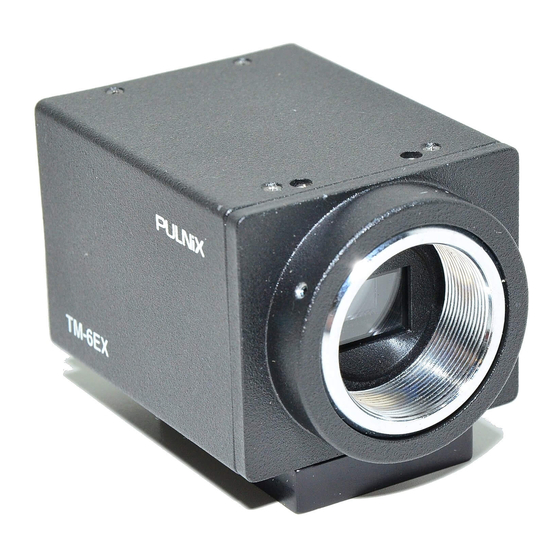
- Page 1 TM-7CN / TM-6CN TM-7EX / TM-6EX TM-72EX/TM-62EX Miniature CCD Cameras Operations Manual rev. 11/15/07...
- Page 3 PLEASE NOTE: The specifications and instructions in this manual apply to the TM-72EX/TM-62EX, with the following exceptions. Imager size: 2/3” interline transfer CCD Pixels: TM-72EX (EIA): 768 (H) x 493 (V) TM-62EX (CCIR): 758 (H) x 581 (V) Cell size: TM-72EX (EIA): 11µm x 13µm TM-62EX (CCIR): 11µm x 11µm TV resolution:...
-
Page 5: Table Of Contents
TABLE OF CONTENTS Page Features and Applications ....................Specifications ........................Physical Dimensions ......................Camera System Accessories ..................12-Pin Connector ....................Shutter Control Unit .................... Power Cables ....................Lenses ........................Power Supplies ....................Setup and Operation ......................Getting Started ...................... Power Supply and Power Cable Setup .............. -
Page 7: Features And Applications
NMR MINIATURIZED AND LIGHTWEIGHT scanners. All PULNiX cameras are built with the same design prin- ciples: solid state technology; miniaturization (including QUICK START-UP AND LOW POWER CONSUMP- lenses, housings, and cables); specialization (such as TION remote imager and image intensified camera versions). -
Page 8: Specifications
Within 90% Vibration: 7G (200Hz to 2000Hz) Shock: Dimensions: TM-7CN 46mm (W) x 40mm (H) x 74mm (L) 1.81" (W) x 1.57" (H) x 2.95" (L) TM-7EX 46mm (W) x 40mm (H) x 79mm (L) 1.81" (W) x 1.57" (H) x 3.11" (L) -
Page 9: Physical Dimensions
SECTION 3 PHYSICAL DIMENSIONS TM-7CN/TM-6CN TM-7EX/6EX 73.9 mm 78.9 mm 45.8 mm 45.8 mm 61.3 mm 66.3 mm P P U U L L N N i i X X P P U U L L N N i i X X 39.4 mm... -
Page 10: Shutter Control Unit
KC-10, etc., be certain that unused leads are not touching and that there is no possibility that leads can 4.4 LENSES - PULNiX offers a wide variety of 2/3 short because of exposed wire (s). inch format mini lenses. Auto-iris lenses must have a... -
Page 11: Attaching The Video Output
The SC-745 Shutter Controller is used to externally To backfocus the TM-7CN, TM-7EX cameras, first vary the shutter speed of the TM-7CN/6CN and TM- attach a C-mount lens in the mount. Be certain that the 7EX/6EX. This controller plugs into the 6-pin connec- lens is properly seated. -
Page 12: Shutter Operation
By selecting D0, D1, D2 level high or low, the following strate underneath each cell, a potential barrier is pulled shutter speeds are obtained, PULNiX provides a shut- down to release the charge into the drain. This can ter control (SC-745), but it is also easily controlled from... -
Page 13: Ccd Characteristics And Operation
SECTION 7 7.2 MECHANISM OF CCD CHARGE TRANSFER CCD CHARACTERISTICS AND 1. Vertical transfer OPERATION The vertical shift register transfers charges using a four- phase drive mode. Figure 1 shows an example of the 7.1 THEORY OF OPERATION (Operation principle of changes which can occur in potential wells in successive the CCD) time intervals. -
Page 14: Spectral Response
FIELD MODE can not provide full frame resolution with strobe lighting application. NOTE: The factory setting for the TM-7 series cameras is FIELD MODE. If FRAME MODE is required please contact PULNiX for the setting. The mode selection is solder jumper on the process board. -
Page 15: Timing Charts
SECTION 8 TIMING CHART 6.7µSec CCD photo sensors allocation Optical H register 69.8nSec black period Image sensing period stop period Dummy Optical H register black period CCD output signal Effective picture period H BLK 10.7µSec Composite video output 1.54µSec H SYNC 52.81µSec 4.47µSec 4.75µSec... -
Page 16: Adjustment Procedure
SECTION 9 ADJUSTMENT PROCEDURE Sync Gen Board Connect Sync Gen board to test jig and check all the functions. 464-01 2352 (YF ONLY) W3 W4 TM-7 SYNC GEN BOARD Jumper setting standard EIA/CCIR selection Open (EIA) Open INT Vinit Short Open Async mode Async/Man shutter... -
Page 17: Imager Board
Mother Board 10.2 Connector Pin Configurations 1 1 1 2 Mother Board Standard TM-7EX/TM-6EX S-option Short Open Open Open +12V IN +12VIN Open Open VIDEO OUT VIDEO OUT Imager Board Connect imager board to test jig and check all Vinit in HD IN the functions. -
Page 18: Phase Adjustment
75Ω R1 HD in Pin 7 VD in 200Ω R2 75Ω R2 75Ω R2 Pin 9 HD in 200Ω R3 75Ω R3 Vinit(Open) 11.2 Jumper setting TM-7CN TM-7EX S-0ption Short Open Open Short Open Open Open T side S side S side T.C side... - Page 20 The material contained in this manual consists of information that is proprietary to PULNiX America, Inc., and may only be used by the purchasers of this product. PULNiX America, Inc. makes no warranty for the use of its products and assumes no responsibility for any errors which may appear or for damages resulting from the use of the information contained herein.


Need help?
Do you have a question about the TM-7CN and is the answer not in the manual?
Questions and answers