Table of Contents
Advertisement
Quick Links
Advertisement
Table of Contents

Summary of Contents for Pulnix TM-9701
-
Page 2: Table Of Contents
Table of Contents Discharge Principle of CCD...................... Substrate Drain Shutter Mechanism..............Asynchronous Shutter..................Shutter Speed Control....................... External Double Pulse Mode................Internal Fast Reset Mode................... Internal Slow Reset Mode.................. Factory Setting and Board Layouts..................Top Board......................Bottom Board..................... Digital Output Connector......................Connector Pin Configurations.................... -
Page 3: Discharge Principle Of Ccd
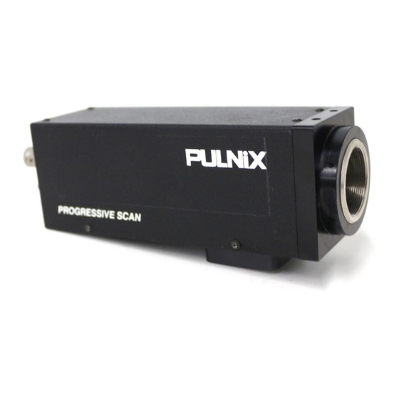
TM-9701 ASYNCHRONOUS RESET FULL FRAME SHUTTER CAMERA OPERATION The TM-9701 is designed to accommodate an ON-LINE inspection reset mechanism with full frame shutter. It takes external horizontal sync to lock the camera and VINIT pulse for resetting the camera asynchronously. -
Page 4: Shutter Speed Control
2. Shutter Speed Control 2.1 External Double Pulse Mode External (min. 10H) Double pulse min. 2H min. 2H Shutter Speed = (x + 9 - 18) H = (x - 9) H Internal Vini Transfer Gate Pulse Exposure Tim Discharge puls Composite Video Fig. -
Page 5: Internal Fast Reset Mode
2.2 Internal Fast Reset Mode External pulse min. 2H Internal Vini Transfer Gate Pulse Exposure Tim Purge pulse (discharg Composite Video Fig. 4 For Internal Fast Reset Mode, set 10-position dial switch from "1" to "4". When fast reset mode is selected, the camera resets with internal VINIT timing, which is latched to Hd, and video output is also synchronized with internal VINIT timing without further delay. -
Page 6: Factory Setting And Board Layouts
Set at 1.5 V p-p AGC MAX Set at 2.5 V ±0.1 V Adjust so that video pedestal level is 50 mV ± 15 mV. A/D REF Refer to Pulnix internal test procedure. D/A GAIN A/D = D/A 3.2 Bottom Board Shutter speed control Built in manual shutter control unit varies the shutter speed. -
Page 7: Digital Output Connector
8 - 15 DO0+ - DO7+ Digital video output ( 8-bit ) 24 - 31 DO0 - - DO7- " Digital output connector is optional. Mating connector ordering information: PULNiX part No. 15-1623 Airborn P/N: MP211-031-113-3400 Straight Backshell (cover): 15-1624 MM254-031-000-0000 Cable assembly: Refer to P.13... -
Page 8: Vinit Double Pulse Generator
7. VINIT Double Pulse Generator One of the advantages of the TM-9701 asynchronous camera is the external shutter speed control by providing a double pulse VINIT signal. The pulses are generally applied from a computer or the frame grabber system. The first pulse is synchronized with the external trigger edge to reset the camera. The second pulse is for shutter speed control and creates internal VD and frame grab timing of asynchronously reset video. -
Page 9: Progressive Scanning
A. Asynchronous Reset Mode (Select switch on back plate for ASYNC) When External VINIT is high ( 5V), the TM-9701 expects the async pulse input. It resets at the negative going pulse edge and captures the frame regardless of the shutter speed (fast or slow mode). The video is kept and output continuously during VINIT high. -
Page 10: Digital Output Pulses
10. Digital Output Pulses 10.1 Digital Video Differential line-driven, 8-bit parallel signal with EIA-422 format. 100Ω output termination impedance. Output from 31-pin connector. The mating connector: Airborn MP211-031-113-4300 (See page 4.) 10.2 Line Data Valid (LDV) Differential line-driven signal with EIA-422 format. It is active high (+ side is higher than - side) during the transfer of each line of data. -
Page 11: Progressive Scan Camera Pixel Map And Timing Chart
ACTIVE PIXEL DUMMY OPTICAL BLACK DUMMY 11.2 Vertical Frame Timing TOTAL HORIZONTAL SCANNING = 525H 484 ACTIVE PIXELS 5 O.B. HORIZONTAL LINES T.G (9H) VIDEO OUTPUT BLANK = 41H NON-INTERLACE EVEN (TM-9701) INTERLACE ODD (TM-9701) PREVIOUS IMAGE (EVEN) NEW VERSION (TM-9701) -
Page 12: Block Diagram
12. Block Diagram 8 BIT DIGITAL VIDEO RS-422 DIRVER RS170 ANALOG VIDEO PROCESS INTERLACE TIMING MEMORY NON-INTERLACE CONT EXT. SYNC IN SYNC VINIT IN ASYNC CONT SHUTTER CONTROL INTEG CONT 13. Signal Delay DOUT VAMP VOUT PIXEL CLOCK : 1N=69.84nsec... -
Page 13: Specifications
Output sensitivity 10 µV/electron Dark noise 40 electrons Dark current < 1 nA/cm Quantum efficiency 25%, 20%, 12% (450, 550, 650 nm); TM-9701 only Scanning: 525 lines, 30 Hz or 60 Hz 2:1 interlace Clock 28.6363 MHz Pixel clock 14.31818 MHz Horizontal frequency 15.734 KHz... -
Page 14: Physical Dimensions
Physical Dimensions PULNiX POWER VIDEO SHUTTER VIDEO OUT PROGRESSIVE SCAN M3x0.5 (4x) 3/8"-16 44.0 mm 18.0 mm 10.2 mm 1/4"-20 35.5 mm 16. 30 Conductor Digital Cable Assembly 31 pin configurations 37 pin configurations Signal Cable Signal Cable Signal Cable... - Page 15 The material contained in this manual consists of information that is proprietary to PULNiX America, Inc., and may only be used by the purchasers of this product. PULNiX America, Inc. makes no warranty for the use of its products and assumes no responsibility for any errors which may appear or for damages resulting from the use of the information contained herein.


Need help?
Do you have a question about the TM-9701 and is the answer not in the manual?
Questions and answers