
Related Manuals for Pulnix TM-250


Summary of Contents for Pulnix TM-250
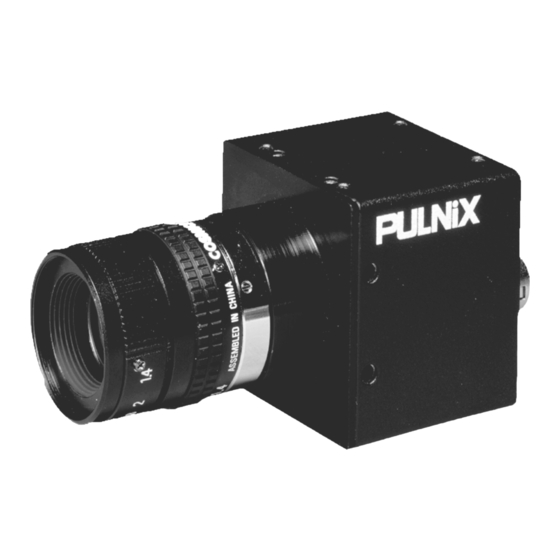
- Page 1 TM-250 Miniature CCD Camera O p e r a t i o n M a n u a l 69-0081 Rev. A I m a g i n g P r o d u c t s...
- Page 2 The material contained in this manual consists of information that is proprietary to PULNiX America, Inc., and may only be used by the purchasers of the product. PULNiX America, Inc. makes no warranty for the use of its product and assumes no responsibility for any errors which may appear or for damages resulting from the use of the information contained herein.
-
Page 3: Table Of Contents
Non-Interlace Operation ....... . . 15 4 TM-250 External Signals ....16 External VD . - Page 4 Table of Contents 5.2.1 TM-250 Strobe Asynchronous Shutter Mode ....22 5.2.2 Post-Reset Asynchronous Shutter Mode ..... 23 5.2.3...
- Page 5 FIGURE 4. TM-250 Timing Chart ........13 FIGURE 5.
- Page 6 TABLE 14. TM-250 Product Specifications Table ......31 TM-250 Miniature CCD Camera...
-
Page 7: Introduction
• High sensitivity The TM-250 camera is one of the most low-light sensitive 1/2" CCD cameras available today. This feature is especially important when using the faster shutter speeds. The CCD detects images into the near-infrared spectrum. It requires only 1.0 lux of minimum illumination and 0.5 lux minimum illumination at maximum gain. -
Page 8: Functional Options
Image capture can begin within a second after turning on the camera. The power consumption is only 2.5W. This makes the camera excellent for use with battery-operated systems. • Camera-mounting flexibility The TM-250 has tapped holes on all four sides to allow a tripod mount to be installed from any angle. • Three-year warranty The CCD solid-state image sensor allows the camera to maintain a superior performance level indefinitely while requiring virtually no maintenance. -
Page 9: Applications
Introduction 1.4 Applications The miniature size of the TM-250 camera eliminates the need for a remoted imager camera in all but the most confined spaces. This camera fits easily, both physically and functionally, into all types of machine vision, automated inspection, and related applications. Other uses include remotely piloted vehicles, miniature inspection devices, surveillance, microscopes, and medical equipment. -
Page 10: Installation
2.2 Camera Setup 2.2.1 Connector Pin Configurations The TM-250 has a 12-pin connector for power input. In general, Pin #1 is Ground and Pin #2 is +12V DC. The other pins handle a number of other input and output functions, as shown in the table below. -
Page 11: Power Supply And Power Cable
2.2.2 (b) PULNiX Power Cables If you are using PULNiX power cables, such as the 12P-02S, please refer to the appropriate pin-out diagram. The color coded leads use Gray for Ground and Yellow for +12V DC. TM-250 Miniature CCD Camera... -
Page 12: Figure 2. 12P-02S Interface Cable (Optional)
Rotate the connector while applying slight pressure until the keyways line up. Press the connector into place until firmly seated. Plug the power cord into the 100V AC socket. This will power the camera up. TM-250 Miniature CCD Camera... -
Page 13: Attaching The Video Output
75Ω termination. Standard RG-59 type coaxial cable should carry a full video signal for up to 500 feet. To output the video and input the power and sync to a camera over a single cable, use the PULNiX multi-conductor cables, such as the 12P-02S, etc. The mini coaxial leads in PULNiX multi-conductor cables are designed for short runs of no longer than 100 feet. -
Page 14: Operation
Note: Functions of the F1 and F2 switches vary depending on the operating mode selected. 3.1.2 Shutter Control Shutter speeds on the TM-250 can be controlled using DIP switches S3, S2, S1, and S0. The following tables show the various switch settings in different operating modes. - Page 15 TABLE 2. Switch Position Shutter Speed (Sec.) Down Down Down Down 1/2,800 Down Down Down Down 1/3,500 Down Down Down 1/4,400 Down Down Down Down 1/6,200 Down Down Down 1/10,200 Down Down Down 1/29,100 F2: not applicable TM-250 Miniature CCD Camera...
-
Page 16: Table 3. Shutter Speed Control In Post-Reset Asynchronous Shutter Mode
1/3,500 Down Down 1/2,800 Down 1/2,400 Down Down Down 1/2,100 Down Down 1/1,800 Down Down 1/1,600 Down 1/1,500 F2 Up: SYNC signal is continuous. F2 Down: SYNC signal is available in one field right after VINIT. TM-250 Miniature CCD Camera... -
Page 17: Field And Frame Modes
3.1.3 Field and Frame Modes The standard factory setting for the TM-250 camera is FRAME MODE. The field and frame integration mode is selectable using the switch on the rear panel of the camera. The frame integration is used to separate all CCD pixels. -
Page 18: External Sync
Page 12 Operation 3.2 External Sync The TM-250 can accept external sync from an external sync generator or frame grabber. Its input specifications are: Internal/External auto switch fH=15.734 KHz ±5%, fV=59.95 Hz ±5% Note: The TM-250 has a one (1) horizontal line delay between the input VD signal and the output video. -
Page 19: Timing
63.56µSec (1 horizontal line) 3.2.2 Interfacing to Frame Grabbers The TM-250 camera can be connected to a frame grabber using either the 12-pin connector or the BNC connector on the rear panel of the camera. 3.3 Operating Modes Besides normal operation, the TM-250 supports the following versatile operations that can be selected by the DIP switch on the rear panel of the camera: •... -
Page 20: Standard Interlace Mode
3.3.2 Cyclic (Continuous) Shutter Mode With back-plate shutter control, the TM-250 operates at the internally predefined shutter speeds. Each field output is exposed for the same period. The shutter control varies the substrate discharge timing. The duration between the shutter pulse and transfer gate timing (11H from VD edge) decides the exposure time (16H for CCIR). -
Page 21: External Sync Mode
Please contact PULNiX for timing charts of various asynchronous shutter modes. 3.3.4 External Sync Mode TM-250 accepts standard RS-170 external sync, which is defined as horizontal sync (HD) and vertical sync (VD). The phase-locked loop jitter is designed to be the minimum (< 5ns) in this category using the latest PLL chip. -
Page 22: Tm-250 External Signals
Async Mode operation, Integration Mode operation, and Reset-Restart operation. 4.1 External VD The TM-250 I/F circuit intentionally delays the external VD for two pixel clock period. This ensures that the phase of external HD comes earlier than that of VD with any cable length and absorbs the effect of jitter caused by the user's sync generators. -
Page 23: Width Mode Reset-Restart Operation
The same happens by the difference of field (odd or even). FIGURE 7. Proper Operation HCLK EXT HD Sample TRIG FIGURE 8. Illegal Operation HCLK EXT HD TRIG (Case A) Exposure (A) TRIG (Case B) Exposure (B) Clocked in here TM-250 Miniature CCD Camera... -
Page 24: Operation Mode
Figure 10 on page 19. The discharge pulse dumps photo-electrons accumulated in the photoreceptor which mechanism is called electronic shutter. Since the discharge pulse is not employed in this mode, we refer this mode to “NO” shutter. TM-250 Miniature CCD Camera... -
Page 25: Fast Shutter Cyclic Mode
The discharge and transfer repeats in every field at a predefined timing. The discharge occurs in every line and stops at the defined timing in one field. The duration between the last discharge and transfer determines exposure time. TM-250 Miniature CCD Camera... -
Page 26: Trigger Position Reset/Restart Shutter Mode
2 lines or more in width. The leading edge of TRIG pulse produces DSUB (discharge) pulse and starts the exposure. The transfer (read-out) occurs at the 11th line after EXT VD pulse is fed. A full picture field can be obtained in every field. The TRIG must be wider than one line. TM-250 Miniature CCD Camera... -
Page 27: Trigger Width Reset/Restart Mode
1st line and the 11th line to ensure shift out of all the transferred charge from the previous transfer in FIELD accumulation mode. This operation is similar to that of Trigger Position shutter, except that the timing is less critical. TM-250 Miniature CCD Camera... -
Page 28: Asynchronous Operation
VINIT pulse implied but before transfer occurs at 11th line for TM-250, and at 16th line for TM-260. When the F2 switch is Up (ON) in Frame storage mode, the camera obtains both odd and even field pictures. -
Page 29: Post-Reset Asynchronous Shutter Mode
The photo transfer occurs at the first line of the odd field right after the reset. Vertical shift starts after 11H for TM-250, and after 16H for TM-260. Only the image in the first odd field is valid. SYNC signal is continuous when F2 switch is Up (ON). -
Page 30: Figure 15. Post-Reset Asynchronous Shutter Mode Timing
1/2,800 Down Down Negative 1/3,500 Down Down Down Negative 1/4,400 Down Down Negative 1/6,200 Down Down Negative 1/10,200 F2 Up: SYNC signal is continuous. F2 Down: SYNC signal is available in one field right after VINIT. TM-250 Miniature CCD Camera... -
Page 31: Pulse Width Asynchronous Shutter Mode
11th line for the TM-250, and the 16th line for the TM-260. For this reason, the exposure TM-250 Miniature CCD Camera... -
Page 32: Figure 17. Pre-Reset Asynchronous Shutter Mode
Operation Mode time can be less than 11 lines for the TM-250 and 16 lines for the TM-260. If the F2 switch is Up (ON), VSYNC is continuously generated and the camera behaves the same as in High-speed Cyclic shutter operation. -
Page 33: Double Pulse Integration Mode
The rising edge of VINIT reset camera and transfer happens at 11th line with TM-250 and at 16th line with TM-260. The transfer occurs only at one field in field accumulation mode or at two fields in frame accumulation mode. SYNC signal is continuous when F2 switch is Up (ON). -
Page 34: Figure 19. Pulse Width Integration Mode
Pulse Width Integration Mode TABLE 13. TRIGGER Polarity Negative F2 Up: SYNC signal is continuous. F2 Down: SYNC signal is available in the two fields (Frame mode) and in one field (Field mode) right after VINIT. TM-250 Miniature CCD Camera... -
Page 35: Troubleshooting
• In Position mode, the trigger starts so that the exposure time in odd and even fields is the same. • In Width mode, the trigger width is the same in the odd and even fields. TM-250 Miniature CCD Camera... -
Page 36: Information And Support Resources
Page 30 Troubleshooting 6.2 Information and Support Resources For further information and support: Phone: (408) 747-0300 (800) 445-5444 (800) 3-PULNIX (24-hour message access) Fax: (408) 747-0660 E-mail: imaging@jaipulnix.com Mail: PULNiX America Inc. Sales Department 1330 Orleans Drive Sunnyvale, CA 94089... -
Page 37: Appendix
Page 31 Appendix Appendix 7.1 Specifications 7.1.1 Product Specifications TM-250 Product Specifications Table TABLE 14. Model TM-250 (EIA) Imager 1/2" Interline transfer CCD, HAD type Pixels 768(H) x 494(V) Cell size 8.4µm x 9.8µm Scanning 525 lines EIA Sync Internal/External auto switch fH=15.734 KHz ±5%,... -
Page 38: Physical Dimensions
18.0 (0.71) GAIN POWER 13.0 (0.51) VIDEO 49.9 (1.96) 8X M3 X 5.0 (0.20) DEEP 44.0 (1.73) 62.6 (2.46) 93.4 (3.68) 20.5 (0.81) 11.0 (0.43) 16.5 (0.65) 11.0 (0.43) 13.0 (0.51) 18.0 (0.71) 2X M6 1/4" —20 TM-250 Miniature CCD Camera... -
Page 39: C-Mount Specifications
Additionally, the shorter flange-back length allows for reduction of the effective diameter of the first lens and reduces the number of lens elements. The common C-Mount lens is completely compatible with a CS-Mount camera when a 5mm extension ring is inserted between the lens and the camera. TM-250 Miniature CCD Camera... -
Page 40: Front End Detail
Appendix 7.1.4 Front End Detail Front End Detail FIGURE 22. 18.11 (0.713) FILTER ICX038DLA IMAGER GASKET IMAGER P W B TM-250 FRONT END 7.2 Spectral Response Spectral Response FIGURE 23. 1000 1100 1200 Wave Length (nm) TM-250 Miniature CCD Camera... - Page 41 I m a g i n g P r o d u c t s JAI PULNiX, Inc. Tel: 408-747-0300 1330 Orleans Drive Tel: 800-445-5444 Sunnyvale, CA 94089 Fax: 408-747-0660 Email: imaging@jaipulnix.com w w w . j a i p u l n i x . c o m 69-0081 Rev.
Need help?
Do you have a question about the TM-250 and is the answer not in the manual?
Questions and answers