Table of Contents
Advertisement
Advertisement
Table of Contents

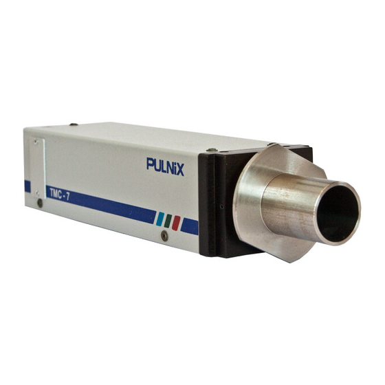
Summary of Contents for Pulnix TMC-7
- Page 1 TMC-7 / TMC-6 HIGH RESOLUTION CCD COLOR CAMERA OPERATIONS MANUAL REV. 7/6/95...
-
Page 2: Table Of Contents
2. SPECIFICATIONS 3. THEORY OF OPERATION Operation Principles of the CCD Mechanism of the CCD Electrical Charge Transmission Interline-Transfer Organization of the CCD Image Sensors Instructions for Powering TMC-7/TMC-6 4. ALIGNMENT AND ADJUSTMENT Equipment Preparation Adjustment Procedures 5. RGB OPERATION (OPTIONAL) CCA-7 RGB "Breakout"... -
Page 3: Operation
1.1 OUTLINE Dark current (thermal noise) is inherent in semicon- The TMC-7 (NTSC model) / TMC-6 (PAL model) is a ductors. At room temperature, the amount of dark compact, lightweight color video camera which uses a current in all photosensors is very close. However, as... -
Page 4: Specifications
SECTION 2: COMPREHENSIVE SPECIFICATIONS Model TMC-7 (NTSC) TMC-6 (PAL) Imager 1/2" interline transfer CCD (6.4 x 4.8 mm) Pixel 768(H) x 494(V) 752(H) x 582(V) Cell size 8.4µm(H) x 9.8µm(V) 8.6µm(H) x 8.3µm(V) Color filter Cy, Ye, Mg, G complementary color filter... -
Page 5: Mechanism Of The Ccd Electrical Charge Transmission
3.2 MECHANISM OF THE CCD ELECTRICAL CHARGE TRANSMISSION The TMC-7 uses a 4-phase drive method CCD. For simplicity, a 2-phase drive method CCD is explained ø2 ø1 below. N- N P - sub Figure 1 shows an example of the changes which can occur in potential wells in successive time intervals. -
Page 6: Interline-Transfer Organization Of The Ccd Image Sensors
The generated charges are fed into the vertical shift registers all at The TMC-7 must use either the 12P Series or C-10 once. The charges are then transferred from the verti- cable. When applying power to the camera, make... - Page 7 12P Series cables available: 3.4.4 AUTO IRIS CONNECTOR 12P-02 2 meters The TMC-7 has a 6-pin auto iris connector located on 12P-05 5 meters the back of the camera. A mating 6-pin connector (PC- 12P-10 10 meters 6P) may be obtained from PULNIX. The lens mount of...
-
Page 8: Alignment And Adjustment
SECTION 4 : ALIGNMENT AND ADJUSTMENT 4.1 EQUIPMENT 1. Light source for test chart. Pattern Box PTB-500 (90-130V) PTB-220 (190-240V--not used in U.S.) 2. For video level and gamma adjustment. Grayscale Chart White Window Chart 3. For color adjustment. MG R (Use color bar chart) Color Bar Chart 4. -
Page 9: Preparation
Note: The following controls for the external control board can be accessed by removing the access port on the left side of the TMC-7. All other presets and adjustments are accessed by removing camera cover. Preset each potentiometer as follows: Matrix board 4.3.2 FUNCTION TEST... - Page 10 R gain, B gain Adjust VR10 and VR11 so that the white spot on Vector scope is in the center. C1 gain Adjust VR12 so that each color dot on the Vector scope combines into one spot. 4.3.4 Y LEVEL, SETUP LEVEL Use Waveform monitor.
-
Page 11: Rgb Operation (Optional)
12V DC input via a terminal for power. To Camera GND +12V (Connect 12P-02MF here) CCA-7 Wavelength (nm) Sync Video Note: RGB option is only available when TMC-7 is modified for use with CCA-7. Contact PULNiX for further assistance. -
Page 12: Timing Chart
SECTION 7: TIMING CHART FOR TMC-7/TMC-6 6.7µSec CCE photo sensors allocation Optical H register 69.8nSec black period Image sensing period stop period Dummy Optical H register black period CCD output signal Effective picture period H BLK 10.7µSec Composite video output 1.54µSec... -
Page 13: Mechanical Drawings
SECTION 8: MECHANICAL DRAWINGS 8.1 STANDARD & REMOTE CONFIGURATIONS PULNiX M2.6 x 7mm. deep (4x) M2 (2x) 1/4 - 20 UNC -2B... - Page 14 The material contained in this manual consists of information that is proprietary to Pulnix America, Inc., and may only be used by the purchasers of this product. Pulnix America, Inc. makes no warranty for the use of its products and assumes no responsibility for any errors which may appear or for damages resulting from the use of the information contained herein.


Need help?
Do you have a question about the TMC-7 and is the answer not in the manual?
Questions and answers