
Related Manuals for Quanmax QDSP-2030


Summary of Contents for Quanmax QDSP-2030
- Page 1 QDSP-2030 Compact-Size Box PC with Intel® Core™2 Duo Processor User’s Guide QDSP-2030 User’s Manual...
- Page 2 © 2009 Quanmax Inc. All rights reserved. The information in this user’s guide is provided for reference only. Quanmax does not assume any liability arising out of the application or use of the information or products described herein. This user’s guide may contain or reference information and products protected by copyrights or patents and does not convey any license under the patent rights of Quanmax, nor the rights of others.
-
Page 3: Table Of Contents
Cooler Installation ................22 Memory Module Installation ..............23 HDD Installation .................. 24 Wall & VESA Mounting ............... 25 Chapter 3 Getting Started ..................28 Power Connection ................28 Operating System and Drivers............29 QDSP-2030 User’s Manual... -
Page 4: Figures
Figure 8 Press down on the SO-DIMM Memory Module to lock it in place 24 Figure 9 HDD Installation ................24 Figure 10 Secure the L-brackets for wall mounting........25 Figure 11 Wall mount holes spacing ............25 Figure 12 VESA-mount kit dimension ............26 Figure 13 VESA Mounting................27 QDSP-2030 User’s Manual... -
Page 5: Tables
Tables Tables Table 1 QDSP-2030 product specifications..........15 QDSP-2030 User’s Manual... -
Page 6: Safety Instructions
Use extreme caution when installing or removing components. Refer to the installation instructions in this user’s guide for precautions and procedures. If you have any questions, please contact Quanmax Post-Sales Technical Support. Access can only be gained by service persons or by users who have been instructed about the reasons for the restrictions applied to the location and about any precautions that shall be taken;... -
Page 7: Preventing Electrostatic Discharge
Static electricity can harm system boards. Perform service at an ESD workstation and follow proper ESD procedure to reduce the risk of damage to components. Quanmax strongly encourages you to follow proper ESD procedure, which can include wrist straps and smocks, when servicing equipment. -
Page 8: Instructions For Lithium Battery
(e.g. to the collecting points for disposal of batteries Voltage Ratings The external power adaptor of the QDSP-2030 has the following voltage ratings: Input: 100-240 VAC Output: 80W, +12VDC, 6.67A max... -
Page 9: Preface
Remove all items from the box. If any items listed on the purchase order are missing, notify Quanmax customer service immediately. Inspect the product for damage. If there is damage, notify Quanmax customer service immediately. Refer to “Warranty Policy” for the return procedure. -
Page 10: Warranty Policy
Quanmax or its authorized agent; or if the failure is caused by accident, acts of God, or other causes beyond the control of Quanmax or the manufacturer. Neglect, misuse, and abuse shall include any installation, operation, or maintenance of the product other than in accordance with the user’s guide. -
Page 11: Maintaining Your Computer
Quanmax. Limitation of Liability In no event shall Quanmax be liable for any defect in hardware, software, loss, or inadequacy of data of any kind, or for any direct, indirect, incidental, or consequential damages in connection with or arising out of the performance or use of any product furnished hereunder. - Page 12 The greatest threats to a system’s supply of power are power loss, power spikes, and power surges caused by electrical storms, which interrupt system operation and/or damage system components. To protect your system, always properly ground power cables and one of the following devices. QDSP-2030 User’s Manual...
- Page 13 Surge protectors should be used with all UPS systems, and the UPS system should be Underwriters Laboratories (UL) safety approved. CAUTION RISK OF EXPLOSION IF BATTERY IS REPLACED BY AN INCORRECT TYPE. DISPOSE OF USED BATTERIES ACCORDING TO THE INSTRUCTIONS QDSP-2030 User’s Manual...
-
Page 14: Chapter 1 Introduction
Chapter 1 Introduction Overview The QDSP-2030 is a compact size Box PC ideal for space critical applications. This embedded hardware platform is based on a 3.5” industrial SBC with Intel® 45 nm Core™2 Duo Processor, Intel® GM45/ICH9-M chipset, and DDR3 800/1066 SO-DIMM. -
Page 15: Product Specifications
Operating: 0°C to 40°C, 0%-90%, non-condensing Humidity Storage: -20°C to 80°C, 0%-90%, non-condensing Dimensions 227 x 44 x 210 mm (WxHxD) Weight 1.8 kg Mounting Wall-Mount, VESA 75/100 Standard Certification CE, FCC Class A Table 1 QDSP-2030 product specifications QDSP-2030 User’s Manual... -
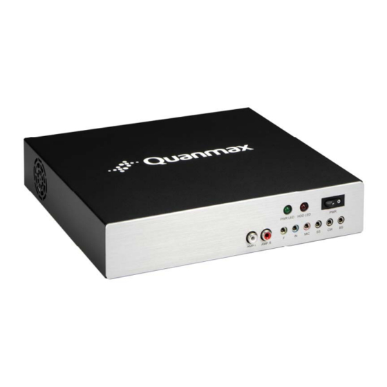
Page 16: Front View Of The Computer
5 Line-Out Audio Jack 10 Back Surround Output Audio Jack Rear view of the computer 1 USB ports 5 DVI-I 2 10/100/1000 LAN port (RJ45) 6 DC-12V IN 3 COM1 (RS-232/422/485, selected by BIOS) 7 Antenna Connector (Option) 4 HDMI QDSP-2030 User’s Manual... -
Page 17: Mechanical Layout
Chapter 1 Mechanical Layout Figure 1 Mechanical Dimensions QDSP-2030 User’s Manual... -
Page 18: Chapter 2 Assembly/Disassembly
Follow the procedure described below to access the system's internal components Loosen the 3 flathead screws from rear side of the computer. Remove the chassis cover off the chassis base. Figure 2 Remove Chassis Cover QDSP-2030 User’s Manual... -
Page 19: Figure 3 Mechanical Layout - Internal Components
Chapter 2 See figure below for the locations of the internal components of the system. Figure 3 Mechanical Layout - Internal Components QDSP-2030 User’s Manual... -
Page 20: Processor Installation
NOTE You should not have to press down on the processor. If the processor does not drop completely into the socket, turn the actuator until the processor drops completely in. QDSP-2030 User’s Manual... -
Page 21: Figure 5 Cpu Alignment In Micro-Fcpga Socket (Socket P)
To remove the CPU, follow Step 2 of Installing the CPU above. Remove the CPU by grasping the substrate edges only with thumb and forefinger and lifting it out with a purely vertical motion. WARNING The CPU and the heat-sink may be hot and could cause burns. QDSP-2030 User’s Manual... -
Page 22: Cooler Installation
Tighten each screw halfway to secure the cooler assembly to the motherboard. Then gradually tighten all four screws. Do not fully tighten the first screw before partially tightening the other screws as this may apply uneven pressure to the CPU, causing damage. QDSP-2030 User’s Manual... -
Page 23: Memory Module Installation
Figure 7 Align the SO-DIMM Memory Module with the onboard socket Fully insert the module into the socket until a “click” is heard. Press down on the SO-DIMM so that the tabs of the socket lock on both sides of the module QDSP-2030 User’s Manual... -
Page 24: Hdd Installation
Step 2 Secure the hard drive to the brackets using the 4 short screws provided. Connecting the SATA data & power cables to the HDD and motherboard then secure the bracket to the chassis. Figure 9 HDD Installation QDSP-2030 User’s Manual... -
Page 25: Wall & Vesa Mounting
Refer to figure below for wall mount holes spacing. The shape of the screw holes allows the QDSP-2030 to be mounted and provides for easy removal of the chassis for repair of maintenance. Use four standard M4 screws to mount the QDSP-2030. -
Page 26: Figure 12 Vesa-Mount Kit Dimension
VESA Mounting The QDSP-2030 comes with an optional VESA FDMI 75/100 standard wall-mount kit which allows the QDSP-2030 to be mounted with a monitor on the wall. NOTE To fasten the metal shelf, your monitor must comply with VESA75 or VESA100 standard and we suggest the monitor size should not exceed 22 inches. -
Page 27: Figure 13 Vesa Mounting
Attach four M4 screws on the wall and hang the system on the screws. Figure 13 VESA Mounting WARNING Ensure that the wall structure is capable of supporting four times the total weight of mounted equipment. The total weight capacity of the wall-mount kit is 14kg. QDSP-2030 User’s Manual... -
Page 28: Chapter 3 Getting Started
Chapter 3 Getting Started Power Connection Connect the power adapter cable to the DC jack (DC IN) of the QDSP-2030 Connect the power cable to the power adapter Connect the power cable to a power outlet Press the power switch on the front panel to turn on the system CAUTION Use the power cord suitable for the power supply in your country. -
Page 29: Operating System And Drivers
You can download the drivers for the product from the Quanmax website at www.quanmax.com and install as instructed there. For other operating systems, please contact Quanmax.
Need help?
Do you have a question about the QDSP-2030 and is the answer not in the manual?
Questions and answers