
Related Manuals for Supero SUPERSERVER 2027GR-TSF


Summary of Contents for Supero SUPERSERVER 2027GR-TSF
- Page 1 UPER ® UPER ERVER 2027GR-TSF 2027GR-TRF 2027GR-TRFT USER’S MANUAL Revision 1.0b...
- Page 2 The information in this User’s Manual has been carefully reviewed and is believed to be accurate. The vendor assumes no responsibility for any inaccuracies that may be contained in this document, makes no commitment to update or to keep current the information in this manual, or to notify any person or organization of the updates.
- Page 3 Preface Preface About This Manual This manual is written for professional system integrators and PC technicians. It provides information for the installation and use of the SuperServer 2027GR- TSF/2027GR-TRF/2027GR-TRFT. Installation and maintenance should be per- formed by experienced technicians only. The 2027GR-TSF/2027GR-TRF/2027GR-TRFT is based on the SC218G-R1800B 2U rackmount server chassis and the Super X9DRG-HF/X9DRG-HTF serverboard.
- Page 4 UPER ERVER 2027GR-TSF/2027GR-TRF/2027GR-TRFT User's Manual Chapter 5: Advanced Serverboard Setup Chapter 5 provides detailed information on the X9DRG-HF/X9DRG-HTF serverboard, including the locations and functions of connectors, headers and jump- ers. Refer to this chapter when adding or removing processors or main memory and when reconfi...
- Page 5 Preface Notes...
-
Page 6: Table Of Contents
UPER ERVER 2027GR-TSF/2027GR-TRF/2027GR-TRFT User's Manual Table of Contents Chapter 1 Introduction Overview ......................1-1 Serverboard Features ..................1-2 Processors ...................... 1-2 Memory ......................1-2 Serial ATA ....................... 1-2 PCI Expansion Slots ..................1-2 Onboard Controllers/Ports ................1-2 IPMI ......................... 1-3 Server Chassis Features ................ - Page 7 Table of Contents Optional Quick Installation Method ..............2-9 Chapter 3 System Interface Overview ......................3-1 Control Panel LEDs ..................3-2 Control Panel Buttons ..................3-2 Drive Carrier LEDs ..................3-4 Chapter 4 Standardized Warning Statements for AC Systems About Standardized Warning Statements ............4-1 Warning Defi...
- Page 8 UPER ERVER 2027GR-TSF/2027GR-TRF/2027GR-TRFT User's Manual Connector Defi nitions ................... 5-15 Jumper Settings .................... 5-21 5-10 Onboard Indicators ..................5-23 5-11 SATA Ports ....................5-24 5-12 Installing Software ..................5-25 SuperDoctor III ....................5-26 5-13 Onboard Battery .................... 5-28 Chapter 6 Advanced Chassis Setup Static-Sensitive Devices ..................
-
Page 9: Chapter 1 Introduction
Chapter 1 Introduction Overview The SuperServer 2027GR-TSF/2027GR-TRF/2027GR-TRFT is a GPU-optimized server comprised of two main subsystems: the SC218G-R1800B 2U server chas- sis and the X9DRG-HF/X9DRG-HTF serverboard. Please refer to our web site for information on operating systems that have been certifi ed for use with the system (www.supermicro.com). -
Page 10: Serverboard Features
UPER ERVER 2027GR-TSF/2027GR-TRF/2027GR-TRFT User's Manual Serverboard Features At the heart of the SuperServer 2027GR-TSF/2027GR-TRF/2027GR-TRFT is the X9DRG-HF/X9DRG-HTF, a dual processor serverboard based on the Intel C602 chipset. Below are the main features of the X9DRG-HF/X9DRG-HTF. (See Figure 1-1 for a block diagram of the chipset). -
Page 11: Ipmi
Chapter 1: Introduction IPMI IPMI (Intelligent Platform Management Interface) is a hardware-level interface speci- fi cation that provides remote access, monitoring and administration for Supermicro server platforms. IPMI allows server administrators to view a server’s hardware status remotely, receive an alarm automatically if a failure occurs, and power cycle a system that is non-responsive. -
Page 12: Gpu Subsystem
UPER ERVER 2027GR-TSF/2027GR-TRF/2027GR-TRFT User's Manual GPU Subsystem The 2027GR-TSF/2027GR-TRF/2027GR-TRFT server represents one of Super- micro's massively parallel processing GPU servers. Four NVIDIA® Fermi™ GPUs place ths system at the forefront of today's GPU computing solutions. NVIDIA Kepler™ GPUs may also be installed to the system. Refer to the NVIDIA web site (www.nvidia.com) for details on Fermi GPUs. - Page 13 Chapter 1: Introduction Figure 1-1. Intel C602 Chipset: System Block Diagram Note: This is a general block diagram. Please see Chapter 5 for details. #0-4 #1-4 #1-3 #0-3 #0-2 #1-2 #0-1 #1-1 CPU1 CPU2 E5-2600 Series E5-2600 Series 8 SNB CORE 8 SNB CORE DDR3 DDR3...
-
Page 14: Contacting Supermicro
UPER ERVER 2027GR-TSF/2027GR-TRF/2027GR-TRFT User's Manual Contacting Supermicro Headquarters Address: Super Micro Computer, Inc. 980 Rock Ave. San Jose, CA 95131 U.S.A. Tel: +1 (408) 503-8000 Fax: +1 (408) 503-8008 Email: marketing@supermicro.com (General Information) support@supermicro.com (Technical Support) Web Site: www.supermicro.com Europe Address: Super Micro Computer B.V. -
Page 15: Chapter 2 Server Installation
Chapter 2: Server Installation Chapter 2 Server Installation Overview This chapter provides a quick setup checklist to get your system up and running. Following these steps in the order given should enable you to have the system operational within a minimum amount of time. This quick setup assumes that your system has come to you with the processors and memory preinstalled. -
Page 16: Warnings And Precautions
UPER ERVER 2027GR-TSF/2027GR-TRF/2027GR-TRFT User's Manual • This product is not suitable for use with visual display work place devices acccording to §2 of the the German Ordinance for Work with Visual Display Units. Warnings and Precautions Rack Precautions • Ensure that the leveling jacks on the bottom of the rack are fully extended to the fl... -
Page 17: Rack Mounting Considerations
Chapter 2: Server Installation Rack Mounting Considerations Ambient Operating Temperature If installed in a closed or multi-unit rack assembly, the ambient operating tempera- ture of the rack environment may be greater than the ambient temperature of the room. Therefore, consideration should be given to installing the equipment in an environment compatible with the manufacturer’s maximum rated ambient tempera- ture (Tmra). -
Page 18: Installing The System Into A Rack
UPER ERVER 2027GR-TSF/2027GR-TRF/2027GR-TRFT User's Manual Installing the System into a Rack This section provides information on installing the chassis into a rack unit with the rails provided. There are a variety of rack units on the market, which may mean that the assembly procedure will differ slightly from the instructions provided. -
Page 19: Locking Tabs
Chapter 2: Server Installation Locking Tabs Each inner rail has a locking tab. This tab locks the chassis into place when installed and pushed fully into the rack. These tabs also lock the chassis in place when fully extended from the rack. This prevents the server from coming completely out of the rack when when the chassis is pulled out for servicing. -
Page 20: Installing The Inner Rails On The Chassis
UPER ERVER 2027GR-TSF/2027GR-TRF/2027GR-TRFT User's Manual Inner Rails Figure 2-3. Installing the Inner Rails Installing The Inner Rails on the Chassis Installing the Inner Rails 1. Confi rm that the left and right inner rails have been correctly identifi ed. Place the inner rail fi rmly against the side of the chassis, aligning the hooks on the side of the chassis with the holes in the inner rail. -
Page 21: Installing The Outer Rails On The Rack
Chapter 2: Server Installation Figure 2-4. Extending and Releasing the Outer Rails Installing the Outer Rails on the Rack Installing the Outer Rails 1. Press upward on the locking tab at the rear end of the middle rail. 2. Push the middle rail back into the outer rail. 3. -
Page 22: Standard Chassis Installation
UPER ERVER 2027GR-TSF/2027GR-TRF/2027GR-TRFT User's Manual Ball-Bearing Shuttle Figure 2-5. Installing the Chassis into a Rack Standard Chassis Installation Installing the Chassis into a Rack 1. Confi rm that the inner rails are properly installed on the chassis. 2. Confi rm that the outer rails are correctly installed on the rack. 3. -
Page 23: Optional Quick Installation Method
Chapter 2: Server Installation Optional Quick Installation Method The following quick installation method may be used to install the chassis onto a rack. Installing the Chassis into a Rack 1. Install the whole rail assembly onto the rack as described previously. 2. - Page 24 UPER ERVER 2027GR-TSF/2027GR-TRF/2027GR-TRFT User's Manual Notes 2-10...
-
Page 25: Chapter 3 System Interface
Chapter 3: System Interface Chapter 3 System Interface Overview The front control panel provides LEDs and buttons for the system. These LEDs provide constant information on the system and on the overall health of system components. There are additional LEDs on each of the drive carriers. This chapter explains the meanings of the LED indicators and the appropriate responses that may need to be taken. -
Page 26: Control Panel Leds
UPER ERVER 2027GR-TSF/2027GR-TRF/2027GR-TRFT User's Manual Control Panel Buttons The SC218G chassis includes two push-buttons located on the control panel: a reset button and a power on/off button. Reset Use the reset button to reboot the system. Power The main power button is used to apply or remove power from the power supply to the server system. - Page 27 Chapter 3: System Interface Indicates IDE channel activity, SATA drive, and/or peripheral drive activity when fl ashing. NIC1 Indicates network activity on GLAN1 when fl ashing. NIC2 Indicates network activity on GLAN2 when fl ashing. Overheat/Fan Fail/UID LED When this LED fl ashes it indicates a fan failure. When continuously on (not fl ash- ing) it indicates an overheat condition, which may be caused by cables obstructing the airfl...
-
Page 28: Drive Carrier Leds
UPER ERVER 2027GR-TSF/2027GR-TRF/2027GR-TRFT User's Manual Power Failure When this LED fl ashes, it indicates a power failure in one of the power supplies. Drive Carrier LEDs Two LEDs are located on the front of each drive carrier. • Green: Each drive carrier has a green LED. When illuminated, this green LED (on the front of the drive carrier) indicates drive activity. -
Page 29: Chapter 4 Standardized Warning Statements For Ac Systems
Chapter 4: Warning Statements for AC Systems Chapter 4 Standardized Warning Statements for AC Systems About Standardized Warning Statements The following statements are industry standard warnings, provided to warn the user of situations which have the potential for bodily injury. Should you have questions or experience difficulty, contact Supermicro's Technical Support department for assistance. - Page 30 UPER ERVER 2027GR-TSF/2027GR-TRF/2027GR-TRFT User's Manual Warnung WICHTIGE SICHERHEITSHINWEISE Dieses Warnsymbol bedeutet Gefahr. Sie befi nden sich in einer Situation, die zu Verletzungen führen kann. Machen Sie sich vor der Arbeit mit Geräten mit den Gefahren elektrischer Schaltungen und den üblichen Verfahren zur Vorbeugung vor Unfällen vertraut.
- Page 31 Warning Statements for AC Systems ﺟﺴﺪﻳﺔ ﺍﺻﺎﺑﺔ ﺗﺘﺴﺒﺐ ﻓﻲ ﺣﺎﻟﺔ ﻳﻤﻜﻦ ﺃﻥ ﺍﻧﻚ ﻓﻲ ﺧﻄﺮ ﻳﻌﻨﻲ ﻫﺬﺍ ﺍﻟﺮﻣﺰ !ﺗﺤﺬﻳﺮ ﺍﻟﺪﻭﺍﺋﺮ ﺑﺎﻟﻤﺨﺎﻁﺮ ﺍﻟﻨﺎﺟﻤﺔ ﻋﻦ ﻦ ﻋﻠﻰ ﻋﻠﻢ ، ﻛ ﻣﻌﺪﺍﺕ ﺗﻌﻤﻞ ﻋﻠﻰ ﺃﻱ ﻗﺒﻞ ﺃﻥ ﺍﻟﻜﻬﺮﺑﺎﺋﻴﺔ ﺣﻮﺍﺩﺙ ﺃﻱ ﻭﻗﻮﻉ ﻤﻨﻊ ﻟ ﺍﻟﻮﻗﺎﺋﻴﺔ...
-
Page 32: Installation Instructions
UPER ERVER 2027GR-TSF/2027GR-TRF/2027GR-TRFT User's Manual Installation Instructions Warning! Read the installation instructions before connecting the system to the power source. 設置手順書 システムを電源に接続する前に、 設置手順書をお読み下さい。 警告 将此系统连接电源前,请先阅读安装说明。 警告 將系統與電源連接前,請先閱讀安裝說明。 Warnung Vor dem Anschließen des Systems an die Stromquelle die Installationsanweisungen lesen. ¡Advertencia! Lea las instrucciones de instalación antes de conectar el sistema a la red de alimentación. -
Page 33: Circuit Breaker
Chapter 4: Warning Statements for AC Systems Circuit Breaker Warning! This product relies on the building's installation for short-circuit (overcurrent) protection. Ensure that the protective device is rated not greater than: 250 V, 20 A. サーキッ ト ・ ブレーカー この製品は、 短絡 (過電流) 保護装置がある建物での設置を前提としています。 保護装置の定格が250 V、... -
Page 34: Power Disconnection Warning
UPER ERVER 2027GR-TSF/2027GR-TRF/2027GR-TRFT User's Manual 경고! 이 제품은 전원의 단락(과전류)방지에 대해서 전적으로 건물의 관련 설비에 의존합니다. 보호장치의 정격이 반드시 250V(볼트), 20A(암페어)를 초과하지 않도록 해야 합니다. Waarschuwing Dit product is afhankelijk van de kortsluitbeveiliging (overspanning) van uw electrische installatie. Controleer of het beveiligde aparaat niet groter gedimensioneerd is dan 220V, 20A. - Page 35 Chapter 4: Warning Statements for AC Systems ¡Advertencia! El sistema debe ser disconnected de todas las fuentes de energía y del cable eléctrico quitado de los módulos de fuente de alimentación antes de tener acceso el interior del chasis para instalar o para quitar componentes de sistema. Attention Le système doit être débranché...
-
Page 36: Equipment Installation
UPER ERVER 2027GR-TSF/2027GR-TRF/2027GR-TRFT User's Manual Equipment Installation Warning! Only trained and qualifi ed personnel should be allowed to install, replace, or service this equipment. 機器の設置 トレーニングを受け認定された人だけがこの装置の設置、 交換、 またはサービスを許可 されています。 警告 只有经过培训且具有资格的人员才能进行此设备的安装、更换和维修。 警告 只有經過受訓且具資格人員才可安裝、更換與維修此設備。 Warnung Das Installieren, Ersetzen oder Bedienen dieser Ausrüstung sollte nur geschultem, qualifi... -
Page 37: Restricted Area
Chapter 4: Warning Statements for AC Systems Waarschuwing Deze apparatuur mag alleen worden geïnstalleerd, vervangen of hersteld door geschoold en gekwalifi ceerd personeel. Restricted Area Warning! This unit is intended for installation in restricted access areas. A restricted access area can be accessed only through the use of a special tool, lock and key, or other means of security. -
Page 38: Battery Handling
UPER ERVER 2027GR-TSF/2027GR-TRF/2027GR-TRFT User's Manual אזור עם גישה מוגבלת !אזהרה יש להתקין את היחידה באזורים שיש בהם הגבלת גישה. הגישה ניתנת בעזרת .('כלי אבטחה בלבד )מפתח, מנעול וכד ﻣﺤﻈﻮﺭﺓ ﻣﻨﺎﻁﻖ ﻟﺘﺮﻛﻴﺒﻬﺎ ﻓﻲ ﻫﺬﻩ ﺍﻟﻮﺣﺪﺓ ﺗﺨﺼﻴﺺ ﺗﻢ ،ﺃﺩﺍﺓ ﺧﺎﺻﺔ ﻣﻦ ﺧﻼﻝ ﺍﺳﺘﺨﺪﺍﻡ ﻓﻘﻂ... - Page 39 Chapter 4: Warning Statements for AC Systems Warnung Bei Einsetzen einer falschen Batterie besteht Explosionsgefahr. Ersetzen Sie die Batterie nur durch den gleichen oder vom Hersteller empfohlenen Batterietyp. Entsorgen Sie die benutzten Batterien nach den Anweisungen des Herstellers. Attention Danger d'explosion si la pile n'est pas remplacée correctement. Ne la remplacer que par une pile de type semblable ou équivalent, recommandée par le fabricant.
-
Page 40: Redundant Power Supplies
UPER ERVER 2027GR-TSF/2027GR-TRF/2027GR-TRFT User's Manual Redundant Power Supplies Warning! This unit might have more than one power supply connection. All connections must be removed to de-energize the unit. 冗長電源装置 このユニッ トは複数の電源装置が接続されている場合があります。 ユニッ トの電源を切るためには、 すべての接続を取り外さなければなりません。 警告 此部件连接的电源可能不止一个,必须将所有电源断开才能停止给该部件供电。 警告 此裝置連接的電源可能不只一個,必須切斷所有電源才能停止對該裝置的供電。 Warnung Dieses Gerät kann mehr als eine Stromzufuhr haben. Um sicherzustellen, dass der Einheit kein trom zugeführt wird, müssen alle Verbindungen entfernt werden. -
Page 41: Backplane Voltage
Chapter 4: Warning Statements for AC Systems ﺍﻣﺪﺍﺩ ﺍﻟﻄﺎﻗﺔ ﺑﻮﺣﺪﺍﺕ ﻋﺪﺓ ﺍﺗﺼﺎﻻﺕ ﺠﻬﺎﺯ ﺍﻟ ﻳﻜﻮﻥ ﻟﻬﺬﺍ ﻗﺪ ﺍﻟﻜﻬﺮﺑﺎء ﻋﻦ ﻮﺣﺪﺓ ﺍﻟ ﻟﻌﺰﻝ ﻛﺎﻓﺔ ﺍﻻﺗﺼﺎﻻﺕ ﻳﺠﺐ ﺇﺯﺍﻟﺔ 경고! 이 장치에는 한 개 이상의 전원 공급 단자가 연결되어 있을 수 있습니다. 이 장치에 전원을... -
Page 42: Comply With Local And National Electrical Codes
UPER ERVER 2027GR-TSF/2027GR-TRF/2027GR-TRFT User's Manual מתח בפנל האחורי !הרה אז קיימת סכנת מתח בפנל האחורי בזמן תפעול המערכת. יש להיזהר במהלך .העבודה ﺍﻟﻠﻮﺣﺔ ﺃﻭﺍﻟﻄﺎﻗﺔ ﺍﻟﻤﻮﺟﻮﺩﺓ ﻋﻠﻰ ﺍﻟﺘﻴﺎﺭ ﺍﻟﻜﻬﺮﺑﺎﺋﻲ ﻣﻦ ﺧﻄﺮ ﻫﻨﺎﻙ ﻫﺬﺍ ﺍﻟﺠﻬﺎﺯ ﺧﺪﻣﺔ ﻛﻦ ﺣﺬﺭﺍ ﻋﻨﺪ ﻳﻌﻤﻞ ﺍﻟﻨﻈﺎﻡ ﻋﻨﺪﻣﺎ ﻳﻜﻮﻥ 경고! 시스템이... -
Page 43: Product Disposal
Chapter 4: Warning Statements for AC Systems Attention L'équipement doit être installé conformément aux normes électriques nationales et locales. תיאום חוקי החשמל הארצי !אזהרה הציוד חייבת להיות תואמת לחוקי החשמל המקומיים והארציים התקנת ﺍﻟﻤﺘﻌﻠﻘﺔ ﺍﻟﻤﺤﻠﻴﺔ ﻭﺍﻟﻮﻁﻨﻴﺔ ﻘﻮﺍﻧﻴﻦ ﻳﺠﺐ ﺃﻥ ﻳﻤﺘﺜﻞ ﻟﻠ ﺍﻟﻜﻬﺮﺑﺎﺋﻴﺔ... -
Page 44: Hot Swap Fan Warning
UPER ERVER 2027GR-TSF/2027GR-TRF/2027GR-TRFT User's Manual ¡Advertencia! Al deshacerse por completo de este producto debe seguir todas las leyes y reglamentos nacionales. Attention La mise au rebut ou le recyclage de ce produit sont généralement soumis à des lois et/ou directives de respect de l'environnement. Renseignez-vous auprès de l'organisme compétent. - Page 45 Chapter 4: Warning Statements for AC Systems 警告 當您從機架移除風扇裝置,風扇可能仍在轉動。小心不要將手指、螺絲起子和其他 物品太靠近風扇。 Warnung Die Lüfter drehen sich u. U. noch, wenn die Lüfterbaugruppe aus dem Chassis genommen wird. Halten Sie Finger, Schraubendreher und andere Gegenstände von den Öffnungen des Lüftergehäuses entfernt. ¡Advertencia! Los ventiladores podran dar vuelta cuando usted quite ell montaje del ventilador del chasis.
-
Page 46: Power Cable And Ac Adapter
UPER ERVER 2027GR-TSF/2027GR-TRF/2027GR-TRFT User's Manual Power Cable and AC Adapter Warning! When installing the product, use the provided or designated connection cables, power cables and AC adaptors. Using any other cables and adaptors could cause a malfunction or a fi re. Electrical Appliance and Material Safety Law prohibits the use of UL or CSA -certifi... - Page 47 Chapter 4: Warning Statements for AC Systems Attention Lors de l'installation du produit, utilisez les bables de connection fournis ou désigné. L'utilisation d'autres cables et adaptateurs peut provoquer un dysfonctionnement ou un incendie. Appareils électroménagers et de loi sur la sécurité Matériel interdit l'utilisation de UL ou CSA câbles certifi...
- Page 48 UPER ERVER 2027GR-TSF/2027GR-TRF/2027GR-TRFT User's Manual Notes 4-20...
-
Page 49: Chapter 5 Advanced Serverboard Setup
Chapter 5: Advanced Serverboard Setup Chapter 5 Advanced Serverboard Setup This chapter covers the steps required to install the X9DRG-HF/X9DRG-HTF serverboard into the chassis, connect the data and power cables and install add-on cards. All serverboard jumpers and connections are also described. A layout and quick reference chart are included in this chapter for your reference. -
Page 50: Unpacking
UPER ERVER 2027GR-TSF/2027GR-TRF/2027GR-TRFT User's Manual Unpacking The serverboard is shipped in antistatic packaging to avoid electrical static dis- charge. When unpacking the board, make sure the person handling it is static protected. Serverboard Installation This section explains the fi rst step of physically mounting the X9DRG-HF/X9DRG- HTF into the SC218G chassis. -
Page 51: Connecting Cables
Chapter 5: Advanced Serverboard Setup Connecting Cables Now that the serverboard is installed, the next step is to connect the cables to the board. These include the data (ribbon) cables for the peripherals and control panel and the power cables. Connecting Data Cables The ribbon cables used to transfer data from the peripheral devices have been care- fully routed to prevent them from blocking the fl... -
Page 52: I/O Ports
UPER ERVER 2027GR-TSF/2027GR-TRF/2027GR-TRFT User's Manual Figure 5-1. Control Panel Header Pins Ground x (Key) x (Key) Power On LED 3.3V HDD LED FP UID/3.3V Stby NIC1 LED (Link) NIC1 LED (Activity) NIC2 LED (Link) NIC2 LED (Activity) OH/Fan Fail/PWR Fail/UID LED Blue LED (UID Cathode) PWR Fail LED 3.3V... -
Page 53: Installing The Processor And Heatsink
Chapter 5: Advanced Serverboard Setup Installing the Processor and Heatsink Warning: Avoid placing direct pressure to the top of the processor package. Always remove the power cord fi rst before adding, removing or changing any hardware com- ponents. Notes: • Always connect the power cord last and always remove it before adding, re- moving or changing any hardware components. - Page 54 UPER ERVER 2027GR-TSF/2027GR-TRF/2027GR-TRFT User's Manual 3. With the lever labeled 'Close 1st' fully retracted, gently push down on the 'Open 1st' lever to open the load plate. Lift the load plate to open it completely. Gently push 4. Using your thumb and the index down to pop the load plate fi...
- Page 55 Chapter 5: Advanced Serverboard Setup Warning: You can only install the CPU to the socket in one direction. Make sure that the CPU is properly inserted into the socket before closing the load plate. If it doesn't close properly, do not force it as it may damage your CPU. Instead, open the load plate again and double-check that the CPU is aligned properly.
-
Page 56: Installing A Cpu Heatsink
UPER ERVER 2027GR-TSF/2027GR-TRF/2027GR-TRFT User's Manual Installing a CPU Heatsink 1. Remove power from the system and unplug the AC power cord from the power supply. 2. Do not apply any thermal grease to the heatsink or the CPU die; the required amount has already been applied. -
Page 57: Memory Support
Chapter 5: Advanced Serverboard Setup Installing Memory Warning: Exercise extreme care when installing or removing DIMM modules to prevent any possible damage. Memory Support The X9DRG-HF/X9DRG-HTF supports up to 256 GB of registered, ECC DDR3- 1600/1333/1066/800 MHz RDIMMs in 8 DIMM slots. See the following tables for memory installation. -
Page 58: Processor/Dimm Population Confi Gurations
UPER ERVER 2027GR-TSF/2027GR-TRF/2027GR-TRFT User's Manual Processor/DIMM Population Confi gurations For memory to work properly, follow the tables below for memory installation. • For memory to operate properly, please install DIMMs in pairs (have an even number of DIMMs installed). • All channels in a system will run at the fastest common frequency. -
Page 59: Expansion Cards
Chapter 5: Advanced Serverboard Setup Expansion Cards Besides offering support for four GPU cards, the 2027GR-TSF/2027GR- TRF/2027GR-TRFT supports PCI expansion cards in the following slots on the serverboard. • One PCI-Express 3.0 x8 low-profi le card (in x16 slot) • One PCI-Express 2.0 x4 standard card (in x16 slot) These slots require the use of a riser card to support expansion cards. -
Page 60: Serverboard Details
UPER ERVER 2027GR-TSF/2027GR-TRF/2027GR-TRFT User's Manual Serverboard Details Figure 5-5. X9DRG-HF/X9DRG-HTF Layout USB/0/1 S/IO JVGA1 JWD1 JPG1 IPMI LAN JLAN2 JLAN1 BMC CTRL LAN CTRL JI2C2 JI2C1 BIOS Battery JBT1 Use SNK-P0047PS CLOSE 1st CPU1 OPEN 1st JPW1 X9DRG-HF Rev. 1.01 Use SNK-P0048PS JPW4 CLOSE 1st... -
Page 61: X9Drg-Hf/X9Drg-Htf Quick Reference
Chapter 5: Advanced Serverboard Setup X9DRG-HF/X9DRG-HTF Quick Reference Jumper Description Default Setting JBT1 Clear CMOS See Section 5-9 JBR1 ME Recovery Pins 2-3 (Normal) JPB1 BMC Enable/Disable Pins 1-2 (Enabled) JPG1 VGA Enable/Disable Pins 1-2 (Enabled) JPL1 LAN1/LAN2 Enable/Disable Pins 1-2 (Enabled) JPME1 Manufacture Mode Pins 2-3 (Normal) - Page 62 UPER ERVER 2027GR-TSF/2027GR-TRF/2027GR-TRFT User's Manual I-SATA 0~5 SATA 3.0 (I-SATA 0/1) and SATA 2.0 Ports (I-SATA 2~5) S-SATA 0~3 SATA 2.0 Ports (S-SATA 0~3) PCI Slot 1/Slot 2 PCI-E 3.0 x16 Slots (Available when CPU1 is populated) PCI Slot 5 PCI-E 3.0 x8 in x16 Slot (Available when CPU1 is populated) PCI Slot 3/Slot 4 PCI-E 3.0 x16 Slots (Available when CPU2 is populated)
-
Page 63: Connector Defi Nitions
Chapter 5: Advanced Serverboard Setup Connector Defi nitions Power Connectors 12V 8-pin Power Three SMC-proprietary power connectors Connector Pin Defi nitions Pins Defi nition are located at JPW1, JPW2 and JPW9 to 1 through 3 +12V provide main power to the serverboard. 4 through 8 Ground Seven 12V, 8-pin power connectors, lo-... - Page 64 UPER ERVER 2027GR-TSF/2027GR-TRF/2027GR-TRFT User's Manual Reset Connector Reset Button Pin Defi nitions (JF1) The reset connector is located on pins 3 Pin# Defi nition and 4 of JF1 and attaches to the reset Reset switch on the computer chassis. See the Ground table on the right for pin defi...
- Page 65 Chapter 5: Advanced Serverboard Setup HDD/FP UID Button The HDD/UID button connections are located on pins 13/14 of JF1. Attach a hard-drive LED cable to display HDD or HDD/UID LED SATA activity. This connection can also be Pin Defi nitions (JF1) used for the front panel UID (Unit Identi- Pin# Defi...
- Page 66 UPER ERVER 2027GR-TSF/2027GR-TRF/2027GR-TRFT User's Manual NMI Button NMI Header Pin Defi nitions The non-maskable interrupt header is lo- Pin# Defi nition cated at JNMI1. Refer to the table on the Control right for pin defi nitions. Ground Internal Buzzer Internal Buzzer Pin Defi...
- Page 67 Chapter 5: Advanced Serverboard Setup TPM/Port 80 Header Pin Defi nitions Pin# Defi nition Pin # Defi nition TPM Header/Port 80 LCLK A Trusted Platform Module/Port 80 header LFRAME# <(KEY)> is located at JTPM1 to provide TPM and LRESET# Port 80 support, which will enhance system LAD 3 LAD 2 performance and data security.
- Page 68 UPER ERVER 2027GR-TSF/2027GR-TRF/2027GR-TRFT User's Manual Unit Identifi er Switch A Unit Identifi er (UID) switch and two LED indicators are provided on the serverboard. UID LED (LE4) Status The rear UID LED (LE4) is located next Color/State OS Status to the rear UID switch. The front panel Blue: Windows OS Unit Identifi...
-
Page 69: Jumper Settings
Chapter 5: Advanced Serverboard Setup Jumper Settings Explanation of Jumpers To modify the operation of the serverboard, jumpers can be used Connector to choose between optional settings. Pins Jumpers create shorts between two pins to change the function of the con- nector. - Page 70 UPER ERVER 2027GR-TSF/2027GR-TRF/2027GR-TRFT User's Manual LAN1/2 Enable/Disable LAN1/2 Enable/Disable Change the setting of jumper JPL1 to en- Jumper Settings able or disable the LAN1/LAN2 Ethernet Jumper Setting Defi nition ports on the serverboard. See the table on Pins 1-2 Enabled the right for jumper settings.
-
Page 71: 5-10 Onboard Indicators
Chapter 5: Advanced Serverboard Setup BMC Enable/Disable BMC Enable/Disable Jumper Settings Use jumper JPB1 to enable or disable the Both Jumpers Defi nition BMC (Baseboard Management Controller), Pins 1-2 Enabled which supports IPMI 2.0/KVM. See the Pins 2-3 Disabled table on the right for jumper settings. 5-10 Onboard Indicators LAN1/2 Port LEDs The Ethernet ports have two LEDs. -
Page 72: 5-11 Sata Ports
UPER ERVER 2027GR-TSF/2027GR-TRF/2027GR-TRFT User's Manual ME Recovery JBR1 is used for ME Firmware Recovery ME Recovery Select mode, which will limit system resource Jumper Settings for essential function use only without Jumper Setting Defi nition putting restrictions on power use. In the Manufacture Mode single operation mode, online upgrade Normal (Default) -
Page 73: 5-12 Installing Software
Chapter 5: Advanced Serverboard Setup 5-12 Installing Software The Supermicro ftp site contains drivers and utilities for your system at ftp://ftp. supermicro.com. Some of these must be installed, such as the chipset driver. After accessing the ftp site, go into the CDR_Images directory and locate the ISO fi... -
Page 74: Superdoctor Iii
UPER ERVER 2027GR-TSF/2027GR-TRF/2027GR-TRFT User's Manual SuperDoctor III The SuperDoctor® III program is a web-based management tool that supports remote management capability. It includes Remote and Local Management tools. The local management is called SD III Client. The SuperDoctor III program allows you to monitor the environment and operations of your system. - Page 75 Chapter 5: Advanced Serverboard Setup Figure 5-8. SuperDoctor III Interface Display Screen (Remote Control) Note: The SuperDoctor III program and User’s Manual can be downloaded from the Supermicro web site at http://www.supermicro.com/products/accessories/soft- ware/SuperDoctorIII.cfm. For Linux, we recommend that you use the SuperDoctor II application instead.
-
Page 76: 5-13 Onboard Battery
UPER ERVER 2027GR-TSF/2027GR-TRF/2027GR-TRFT User's Manual 5-13 Onboard Battery Please handle used batteries carefully. Do not damage the battery in any way; a damaged battery may release hazardous materials into the environment. Do not discard a used battery in the garbage or a public landfi ll. Please comply with the regulations set up by your local hazardous waste management agency to dispose of your used battery properly. -
Page 77: Chapter 6 Advanced Chassis Setup
Chapter 6: Advanced Chassis Setup Chapter 6 Advanced Chassis Setup This chapter covers the steps required to install components and perform mainte- nance on the SC218G chassis. For component installation, follow the steps in the order given to eliminate the most common problems encountered. If some steps are unnecessary, skip ahead to the next step. -
Page 78: Control Panel
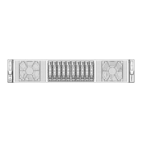
UPER ERVER 2027GR-TSF/2027GR-TRF/2027GR-TRFT User's Manual Figure 6-1. Chassis: Front and Rear Views Control Panel Drive Bays 0-7 Low-Profi le PCI-E Slots (2) Standard Size PCI-E Slots (3) Note: the number of PCI slots available depend on the presence of GPUs in the server model. - Page 79 Chapter 6: Advanced Chassis Setup Replacing a System Fan (Figure 6-2) 1. Remove the chassis cover. If necessary, do this with the power on in order to determine which fan has failed, then power-down the system and disconnect the chassis power cord. 2.
- Page 80 UPER ERVER 2027GR-TSF/2027GR-TRF/2027GR-TRFT User's Manual 3. Lift the fan housing up and out of the chassis. 4. Disconnect the wiring to the fan. 5. Examine the drawings below, then disassemble the fan housing by removing the front and rear fan guards (A). 6.
-
Page 81: System Fans
Chapter 6: Advanced Chassis Setup Installing the Air Shroud Air shrouds concentrate airfl ow to maximize fan effi ciency. The SC218G air shroud is composed of one upper piece and one lower piece. Installing the Air Shroud 1. Position the lower piece of the air shroud in the chassis behind the two system fans, aligning the mounting holes of the air shroud with those of the chassis. -
Page 82: Drive Bay Installation/Removal
UPER ERVER 2027GR-TSF/2027GR-TRF/2027GR-TRFT User's Manual Drive Bay Installation/Removal The hard drives are mounted in drive carriers to simplify their installation and removal from the chassis. These carriers also help promote proper airfl ow for the drive bays. For this reason, even empty carriers without drives installed must remain in the chassis. - Page 83 Chapter 6: Advanced Chassis Setup Dummy Drive Hard Drive Carrier Figure 6-7. Removing a Dummy Drive from the Drive Carrier Installing a Hard Drive into a Drive Carrier 1. Remove the four screws securing the dummy drive to the hard drive carrier. 2.
-
Page 84: Expansion Card Setup
UPER ERVER 2027GR-TSF/2027GR-TRF/2027GR-TRFT User's Manual Expansion Card Setup The SC218G supports the following PCI-Express expansion cards and an expan- sion card bracket: • One low-profi le PCI-E 3.0 (x8) card (in x16 slot) • One full-height, full-length PCI-E 2.0 (x4) card (in x16 slot) Figure 6-9. - Page 85 Chapter 6: Advanced Chassis Setup Figure 6-10. Installing Expansion Cards into the Expansion Card Bracket Figure 6-11. Installing the Expansion Card Bracket into the Chassis...
-
Page 86: Low-Profi Le Expansion Card Setup
UPER ERVER 2027GR-TSF/2027GR-TRF/2027GR-TRFT User's Manual Figure 6-12. Installing a Low-Profi le Expansion Card Low-Profi le Expansion Card Setup The SC218G supports one low-profi le PCI-E 2.0 (x8) expansion card slot for use with a riser card. The SC218G chassis has two low-profi le PCI slots available in order to accomodate a variety of riser card and add-on card combinations. -
Page 87: Installing Graphics (Gpu) Cards
Chapter 6: Advanced Chassis Setup Installing Graphics (GPU) Cards The SC218G chassis supports four GPU cards, which are mounted in brackets to fi t into the PCI-E 3.0 slots at the front of the chassis. NVIDIA Fermi M2090, Fermi M2075 and NVIDIA Kepler K10 GPUs are supported. The GPU cards may be preinstalled, the procedure below is provided for when a GPU card needs to be replaced. - Page 88 UPER ERVER 2027GR-TSF/2027GR-TRF/2027GR-TRFT User's Manual Figure 6-13. Installing GPU Cards into the Left and Right GPU Brackets Airfl ow Left Side GPU Bracket Right Side GPU Bracket and Cards and Cards Important Note for Kepler GPUs: note the airfl ow arrows on top of the GPU card. The card with the arrow pointing toward the Tesla logo should go on the left side of the chassis, and the card with the arrow pointing away from the Tesla logo should go on the right side of the chassis (when viewed from the front of the system).
-
Page 89: Power Supply
Chapter 6: Advanced Chassis Setup Power Supply The system includes either a single (2027GR-TSF) or dual (2027GR-TRF/2027GR- TRFT) 1800 Watt power supply, which is auto-switching capable. The power supply automatically senses and operates at a 100v to 240v input voltage. Note that differ- ent input voltages will result in different maximum power output levels. - Page 90 UPER ERVER 2027GR-TSF/2027GR-TRF/2027GR-TRFT User's Manual Figure 6-15. Removing the Power Supply 6-14...
-
Page 91: Chapter 7 Bios
Chapter 7: BIOS Chapter 7 BIOS Introduction This chapter describes the AMI BIOS Setup utility for the X9DRG-HF/HTF. It also provides the instructions on how to navigate the AMI BIOS Setup utility screens. The AMI ROM BIOS is stored in a Flash EEPROM and can be easily updated. Starting BIOS Setup Utility To enter the AMI BIOS Setup utility screens, press the <Del>... -
Page 92: How To Change The Confi Guration Data
UPER ERVER 2027GR-TSF/2027GR-TRF/2027GR-TRFT User's Manual How To Change the Confi guration Data The confi guration data that determines the system parameters may be changed by entering the AMI BIOS Setup utility. This Setup utility can be accessed by pressing <Delete> at the appropriate time during system boot. Note: For AMI UEFI BIOS Recovery, please refer to the UEFI BIOS Re- covery User Guide posted @http://www.supermicro.com/support/manuals/. - Page 93 Chapter 7: BIOS The AMI BIOS Main menu displays the following information: System Date/System Time Use this option to change the system time and date. Highlight System Time or System Date using the arrow keys. Enter new values through the keyboard and press <Enter>.
-
Page 94: Advanced Setup Confi Gurations
UPER ERVER 2027GR-TSF/2027GR-TRF/2027GR-TRFT User's Manual Advanced Setup Confi gurations Select the Advanced tab to access the following submenu items. Boot Features Quiet Boot This feature allows the user to select bootup screen display between POST mes- sages and the OEM logo. Select Disabled to display the POST messages. Select Enabled to display the OEM logo instead of the normal POST messages. - Page 95 Chapter 7: BIOS Interrupt 19 Capture Interrupt 19 is the software interrupt that handles the boot disk function. When this item is set to Enabled, the ROM BIOS of the host adaptors will "capture" Interrupt 19 at bootup and allow the drives that are attached to these host adaptors to function as bootable disks.
- Page 96 UPER ERVER 2027GR-TSF/2027GR-TRF/2027GR-TRFT User's Manual • CPU Stepping • Maximum CPU Speed • Minimum CPU Speed • Processor Cores • Intel HT (Hyper-Threading) Technology • Intel VT-x Technology • Intel SMX Technology • L1 Data Cache • L1 Code Cache •...
- Page 97 Chapter 7: BIOS Active Processor Cores Set to Enabled to use a processor's second core and above. (Please refer to Intel's website for more information.) The options are All, 1, 2, 4 and 6. Limit CPUID Maximum This feature allows the user to set the maximum CPU ID value. Enable this function to boot the legacy operating systems that cannot support processors with extended CPUID functions.
- Page 98 UPER ERVER 2027GR-TSF/2027GR-TRF/2027GR-TRFT User's Manual Intel® Virtualization Technology (Available when supported by the CPU) Select Enabled to support Intel Virtualization Technology, which will allow one platform to run multiple operating systems and applications in independent parti- tions, creating multiple "virtual" systems in one physical computer. The options are Enabled and Disabled.
- Page 99 Chapter 7: BIOS CPU C6 Report (Available when Power Technology is set to Custom) Select Enabled to allow the BIOS to report the CPU C6 State (ACPI C3) to the operating system. During the CPU C6 State, the power to all cache is turned off.
- Page 100 UPER ERVER 2027GR-TSF/2027GR-TRF/2027GR-TRFT User's Manual Short Duration Power Limit This item displays the time period during which short duration power is main- tained. The default setting is 0. Chipset Confi guration North Bridge This feature allows the user to confi gure the settings for the Intel North Bridge. Integrated IO Confi...
- Page 101 Chapter 7: BIOS CPU1 Slot 2 PCI-E 3.0 x16 OPROM This feature allows the user to set the PCI-Exp bus speed for the slot specifi ed above. The options are Gen1 (Generation 1), Gen2 and Gen3. CPU1 Slot 1 PCI-E 3.0 x16 OPROM This feature allows the user to set the PCI-Exp bus speed for the slot specifi...
- Page 102 UPER ERVER 2027GR-TSF/2027GR-TRF/2027GR-TRFT User's Manual DIMM Confi guration This section displays the following DIMM information. Current Memory Mode This item displays the current memory mode. Current Memory Speed This item displays the current memory speed. Mirroring This item displays if memory mirroring is supported by the motherboard. Memory mirroring creates a duplicate copy of the data stored in the memory to enhance data security.
- Page 103 Chapter 7: BIOS Channel Interleaving This feature selects from the different channel interleaving methods. The options are Auto, 1 Way, 2 Way, 3, Way, and 4 Way. Rank Interleaving This feature allows the user to select a rank memory interleaving method. The options are Auto, 1 Way, 2 Way, 4, Way, and 8 Way.
- Page 104 UPER ERVER 2027GR-TSF/2027GR-TRF/2027GR-TRFT User's Manual South Bridge Confi guration This feature allows the user to confi gure the settings for the Intel PCH chip. PCH Information This feature displays the following PCH information. Name: This item displays the name of the PCH chip. Stepping: This item displays the status of the PCH stepping.
- Page 105 Chapter 7: BIOS SATA Mode Use this feature to confi gure SATA mode for a selected SATA port. The options are Disabled, IDE Mode, AHCI Mode and RAID Mode. The following are displayed depending on your selection: IDE Mode The following items are displayed when IDE Mode is selected: Serial-ATA (SATA) Controller 0~1 Use this feature to activate or deactivate the SATA controller, and set the compatibility mode.
- Page 106 UPER ERVER 2027GR-TSF/2027GR-TRF/2027GR-TRFT User's Manual SCU (Storage Control Unit) Confi guration Storage Controller Unit Select Enabled to enable PCH SCU storage devices. The options are Disabled and Enabled. OnChip SCU Option ROM Select Enabled to support the onboard SCU Option ROM to boot up the system via a storage device.
- Page 107 Chapter 7: BIOS Maximum Read Request Select Auto to allow the system BIOS to automatically set the maximum Read Request size for a PCI-E device to enhance system performance. The options are Auto, 128 Bytes, 256 Bytes, 512 Bytes, 1024 Bytes, 2048 Bytes, and 4096 Bytes. ASPM Support This feature allows the user to set the Active State Power Management (ASPM) level for a PCI-E device.
- Page 108 UPER ERVER 2027GR-TSF/2027GR-TRF/2027GR-TRFT User's Manual Super IO Confi guration Super IO Chip: This item displays the Super IO chip used in the motherboard. Serial Port 1 Confi guration Serial Port Select Enabled to enable a serial port specifi ed by the user. The options are En- abled and Disabled.
- Page 109 Chapter 7: BIOS Device Mode Use this feature to select the desired mode for a serial port specifi ed. The options are Normal and High Speed. Serial Port Console Redirection COM 1/SOL These two submenus allow the user to confi gure the following Console Redirection settings for a COM Port specifi...
- Page 110 UPER ERVER 2027GR-TSF/2027GR-TRF/2027GR-TRFT User's Manual is odd. Select None if you do not want to send a parity bit with your data bits in transmission. Select Mark to add a mark as a parity bit to be sent along with the data bits.
- Page 111 Chapter 7: BIOS Console Redirection Select Enabled to use a COM Port selected by the user for Console Redirection. The options are Enabled and Disabled. Console Redirection Settings This feature allows the user to specify how the host computer will exchange data with the client computer, which is the remote computer used by the user.
- Page 112 UPER ERVER 2027GR-TSF/2027GR-TRF/2027GR-TRFT User's Manual ACPI Sleep State Use this feature to select the ACPI State when the system is in sleep mode. Select S1 (CPU_Stop_Clock) to erase all CPU caches and stop executing instructions. Power to the CPU(s) and RAM is maintained, but RAM is refreshed. Select Sus- pend Disabled to use power-reduced mode.
- Page 113 Chapter 7: BIOS TPM Active Status This item displays the status of TPM Support to indicate if TPM is currently ac- tive or deactivated. TPM Owner Status This item displays the status of TPM Ownership. Intel TXT (LT-SX) Confi guration Intel TXT (LT-SX) Hardware Support This feature indicates if the following hardware components support the Intel Trusted Execution Technology.
- Page 114 UPER ERVER 2027GR-TSF/2027GR-TRF/2027GR-TRFT User's Manual iSCSI Confi guration: This item displays iSCSI confi guration information: iSCSI Initiator Name This item displays the name of the iSCSI Initiator, which is a unique name used in the world. The name must use IQN format. The following actions can also be performed: •...
-
Page 115: Event Logs
Chapter 7: BIOS • Chip Type • PCI Device ID • PCI Bus:Device:Function • Link Status • Factory MAC Address • Alternate MAC Address Event Logs Select the Event Logs tab to access the following submenu items. Change SMBIOS Event Log Settings This feature allows the user to confi... - Page 116 UPER ERVER 2027GR-TSF/2027GR-TRF/2027GR-TRFT User's Manual Runtime Error Logging Support Select Enabled to support Runtime Error Logging. The options are Enabled and Disabled. Memory Correctable Error Threshold This feature allows the user to enter the threshold value for correctable memory errors. The default setting is 10. PCI Error Logging Support Select Enabled to support error event logging for PCI slots.
-
Page 117: Ipmi
Chapter 7: BIOS View System Event Log This item allows the user to view the event in the system event log. Select this item and press <Enter> to view the status of an event in the log. Date/Time/Error Code/Severity IPMI Select the IPMI (Intelligent Platform Management Interface) tab to access the fol- lowing submenu items. - Page 118 UPER ERVER 2027GR-TSF/2027GR-TRF/2027GR-TRFT User's Manual Erasing Settings Erase SEL Select Yes, On next reset to erase all system event logs upon next system reboot. Select Yes, On every reset to erase all system event logs upon each system reboot. Select No to keep all system event logs after each system reboot. The options are No, Yes, On next reset, and Yes, On every reset.
-
Page 119: Boot
Chapter 7: BIOS Subnet Mask This item displays the sub-network that this computer belongs to. The value of each three-digit number separated by dots should not exceed 255. Station MAC Address This item displays the Station MAC address for this computer. Mac addresses are 6 two-digit hexadecimal numbers. -
Page 120: Security
UPER ERVER 2027GR-TSF/2027GR-TRF/2027GR-TRFT User's Manual Delete Boot Option This feature allows the user to select a EFI boot device to delete from the boot priority list. Delete Boot Option Select the desired boot device to delete. Security This menu allows the user to confi gure the following security settings for the system. -
Page 121: Save & Exit
Chapter 7: BIOS Save & Exit This submenu allows the user to confi gure the Save and Exit settings for the system. Discard Changes and Exit Select this option to quit the BIOS Setup without making any permanent changes to the system confi guration, and reboot the computer. Select Discard Changes and Exit, and press <Enter>. - Page 122 UPER ERVER 2027GR-TSF/2027GR-TRF/2027GR-TRFT User's Manual Discard Changes Select this feature and press <Enter> to discard all the changes and return to the BIOS setup. When the dialog box appears, asking you if you want to load previ- ous values, click Yes to load the values previous saved, or click No to keep the changes you've made so far.
-
Page 123: Appendix A Bios Post Error Codes
Appendix A: BIOS POST Error Codes Appendix A BIOS POST Error Codes During the POST (Power-On Self-Test) routines, which are performed each time the system is powered on, errors may occur. Non-fatal errors are those which, in most cases, allow the system to continue the boot-up process. - Page 124 UPER ERVER 2027GR-TSF/2027GR-TRF/2027GR-TRFT User's Manual Notes...
-
Page 125: Appendix B System Specifi Cations
Appendix B: System Specifi cations Appendix B System Specifi cations Processors Two Intel Xeon E5-2600 series processors Note: Please refer to our web site for a complete listing of supported processors. Chipset Intel C602 BIOS 32 Mb AMIBIOS® SPI Flash ROM Memory Capacity Eight DIMM sockets supporting up to 256 GB of registered ECC DDR3- 1600/1333/1066/800 MHz RDIMMs... - Page 126 UPER ERVER 2027GR-TSF/2027GR-TRF/2027GR-TRFT User's Manual Serverboard 2027GR-TSF, 2027GR-TRF: X9DRG-HF (proprietary form factor) 2027GR-TRFT: X9DRG-HTF (proprietary form factor) Dimensions: 19.7" x 9.2" (500.4 x 233.7 mm) Chassis SC218G-R1800B (2U rackmount) Dimensions: (WxHxD) 17.2 x 3.5 x 30.5 in. (437 x 89 x 775 mm) System Cooling Five 8-cm heavy-duty cooling fans (fan speed controlled by BIOS setting) System Input Requirements...
- Page 127 Appendix B: System Specifi cations Regulatory Compliance Electromagnetic Emissions: FCC Class A, EN 55022 Class A, EN 61000-3-2/-3- 3, CISPR 22 Class A Electromagnetic Immunity: EN 55024/CISPR 24, (EN 61000-4-2, EN 61000-4-3, EN 61000-4-4, EN 61000-4-5, EN 61000-4-6, EN 61000-4-8, EN 61000-4-11) Safety: CSA/EN/IEC/UL 60950-1 Compliant, UL or CSA Listed (USA and Canada), CE Marking (Europe) California Best Management Practices Regulations for Perchlorate Materials:...
- Page 128 UPER ERVER 2027GR-TSF/2027GR-TRF/2027GR-TRFT User's Manual Notes...
Need help?
Do you have a question about the SUPERSERVER 2027GR-TSF and is the answer not in the manual?
Questions and answers