Table of Contents
Advertisement
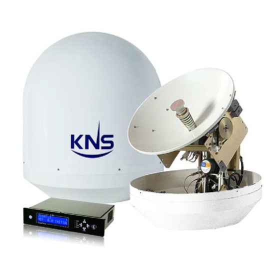
Installation AND OPERATION MANUAL
FOR SUPERTRACK MODEL S4
Ku-BAND TV-RO ANTENNAS
KNS Inc.
Tel)+82-42-932-0351~2
Fax)+82-42-932-0353
Web) http://kns-kr.com/
28.03. 2011
Advertisement
Table of Contents

Summary of Contents for KNS SUPERTRACK S4
- Page 1 INSTALLATION AND OPERATION MANUAL FOR SUPERTRACK MODEL S4 Ku-BAND TV-RO ANTENNAS KNS Inc. Tel)+82-42-932-0351~2 Fax)+82-42-932-0353 Web) http://kns-kr.com/ 28.03. 2011...
- Page 2 All Rights Reserved. The information contained in this document is proprietary to KNS, Inc. This document may not be reproduced or distributed in any form without the consent of KNS, Inc. The information in this document is subject to change without notice.
- Page 3 Revision History Revision Date Description Remarks 02.22. 2010 Initial Release Hong (PCU Ver. 1.95 & ACU Ver. S1.12) 05.17. 2010 Update text and figures about Hong changed ACU software (PCU Ver. 1.96 & ACU Ver. E1.20) 10.07. 2010 Update text and figure about PCU Hong changes from DVB S1 to DVB S2 (PCU Ver.
-
Page 4: Table Of Contents
Contents 1. Introduction .................. 1 1.1. Purpose ....................1 2. Installation ..................2 2.1. Site Selection ..................2 2.2. Unpacking the Unit ................4 2.3. Equipment and Cable Installation ............5 2.4. Antenna Unit Mounting ............... 6 2.5. ACU Mounting ..................10 2.6. -
Page 5: Introduction
Although installations may be completed by the customer’s preferred personnel, it is also recommended that personnel be trained in the KNS suite of equipment installation procedures and trained by the relevant KNS Inc. experts. -
Page 6: Installation
2. Installation 2.1. Site Selection Determine the optimum mounting location for the antenna radome assembly. It should be installed where: 1. The antenna has a clear line-of-sight view of as much of the sky as is practical. Choose a location where masts or other structures do not block the satellite signal from the dish as the boat turns. - Page 7 Figure 2-2 Best Location II Figure 2-3 Antenna Blockages...
-
Page 8: Unpacking The Unit
2.2. Unpacking the Unit Cut the band and remove the items of antenna equipment. Do not turn the box on its side to tip or roll out the product, or turn the box upside down to remove it. Lift carton box straight up Figure 2-4 Unpack the Antenna... -
Page 9: Equipment And Cable Installation
2.3. Equipment and Cable Installation The coax connector bracket beneath the radome is labeled. The functional assignment of these labels is as follows: S4 Connectors RF1: Connect to the multi-switch (Vertical Low). RF2: Connect to the multi-switch (Horizontal Low). RF3: Connect to the multi-switch (Vertical High). RF4: Connect to the multi-switch (Horizontal High). -
Page 10: Antenna Unit Mounting
2.4. Antenna Unit Mounting Drill four bolt holes and cut out a cable access hole on the mounting site. (See reference appendix.) Position the foam seal on the mounting surface with the hole centered over the cable access cut-out. Position the base plate over the mounting holes and the cable access hole, and then align the radome base plate’s “Bow”... - Page 11 Figure 2-7 Tighten the nuts from below...
- Page 12 3. Remove the jigs and wire ties holding the Antenna. Please refer to Figures 2-8 and 2-9, 2-10 below. Figure 2-8 Fixed Screw for Elevation Figure 2-9 Fixed Screws for Cross...
- Page 13 Fixed Screws for Azimuth Figure 2-10 Fixed Screws for Azimuth...
-
Page 14: Acu Mounting
2.5. ACU Mounting The ACU may be mounted either horizontally or vertically. 1. The ACU should be placed in a dry location that is convenient for the user. 2. It must be situated in a place that is not susceptible to magnetic interference; nor must it be situated on a level surface. -
Page 15: Gyro Connection(Optional)
2.6. Gyro Connection(Optional) The SuperTrack S4 receives NMEA-type gyro signals when the compass mode is ‘Gyro’. Connect the NMEA port of the ACU back panel with a ship’s gyro using a 9-pin connector (female type). Figure 2-12 NMEA connector Figure 2-13 Female-type 9-pin connector... - Page 16 Gyro Cable Connection The cable connection differs according to the type of NMEA. Connect the NMEA port with the ship’s gyro, as indicated in Figures 2-14 and 2-15 below. Pin No. Pin Name DC 24V Dummy Dummy Dummy Table 2-1 Using the pin number of the ACU Connector for the NMEA type Figure 2-14 Cable Connection NMEA 422/485 Figure 2-15 Cable Connection NMEA 232...
- Page 17 NOTE: KA-70 ACU can receive the various format of NMEA, as follow: HDT; HDG; HDM. KA-70 ACU(ver. E.1.23) can accept the gyro signal even though there is no checksum as below. $HEHDT,x.x,T*hh<CR><LF> $HEHDG,x.x,x.x,a,x.x,a*hh<CR><LF> *hh means checksum of format.
-
Page 18: Cable Connection
2.7. Cable Connection For the SuperTrack S4 to work, you must connect the RF cables to your satellite TV receiver(s). Each RF cable must be an RF (75 ohms) cable fitted with F-type connectors. The RF cables should already be connected to the antenna base plate. - Page 19 NOTE: Before you connect an RF cable to a satellite TV receiver, turn on the satellite TV receiver and TV and verify that there is no AC voltage on the satellite TV receiver’s input connector, as measured between the center conductor and the shield. If AC voltage is present on the connector, DO NOT connect the RF cable until you have corrected the problem.
- Page 20 ACU and the satellite TV receiver. The RF4 connector of the SuperTrack S4 must be connected to the “SAT IN” connector of the satellite receiver. And, the “ACU” connector of the Antenna unit must also be connected to the “ANTENNA”...
- Page 21 In European systems that come with a Quattro LNB (optional Quad LNB), all four RF outputs from the SuperTrack S4 antenna should be connected to the multi-switch. Connect each of the satellite TV receiver’s inputs to the output connectors on the multi- switch.
- Page 22 Connecting satellite TV receivers signal with European LNB when auto switching using the DiSEqC signal (Use of the all polarity of satellite) If the satellite TV receiver supports the DiSEqC function, you can automatically change the satellite using DiSEqC. To send the DiSEqC signal to the ACU via the satellite TV receivers, one splitter should be installed between the Master satellite TV receiver and the ACU, as shown in Figure 2-19.
- Page 23 RF1 RF2 RF3 RF4 ACU Power/Data Vertical Horizontal Vertical Horizontal /Low /Low /High /High Multiswitch OUT3 OUT1 OUT2 OUT4 IRD #2 IRD #3 IRD #4 Passive * Pass Splitter SAT IN ANTENNA RECEIVER Master IRD Antenna Control Unit (ACU) 90~230VAC Diagnostics 50~60Hz *We recommend Aspen’s P7002 splitter.
- Page 24 LNB for option. To connect three or four satellite TV receivers to the SuperTrack S4 antenna, you will need to install an active multi-switch (Channel Master - model 141FD or equivalent) between the antenna and the satellite TV receivers.
- Page 25 RF1 RF2 RF3 RF4 ACU Power/Data Multiswitch OUT3 OUT1 OUT2 OUT4 IRD #2 IRD #3 IRD #4 Passive * Pass Splitter SAT IN ANTENNA RECEIVER Master IRD Antenna Control Unit (ACU) 90~230VAC Diagnostics 50~60Hz *We recommend Aspen’s P7002 splitter. Figure 2-20 Multi-satellite TV receiver Installation with Auto-Switching...
-
Page 26: Operation
3. Operation 3.1. Front Panel Functions 1. MENU button – Press the MENU button for more than 3 seconds to enter the set-up mode. When you want to escape from the set-up mode, press MENU again for more than 3 seconds. Another function of the MENU button is that of checking the error message when the S4 makes an error. - Page 27 5. SEARCH button – Press SEARCH for more than 3 seconds to re-search for the current satellite. This button is also used to scroll down (▼) in the menu. 6. PWR button (Power button) – Use this button when you want to turn on/off the antenna unit power.
- Page 28 Figure 3-3 Antenna Control Unit Back Panel...
-
Page 29: Acu Display Operation
3.2. ACU Display Operation If you turn on the power switch of the antenna control unit, you can view the steps shown in Figure 3-4 below. Figure 3-4 Display Flow on the ACU LCD Display of the Antenna State INITIAL (Initializing): The ACU displays ‘INITIAL’ on the LCD when the antenna is initializing. - Page 30 PCU isn’t supplying the torque to all motors to protect the antenna. In this case, the ACU will display ‘HALT’ on the LCD. The antenna continues in ‘halt’ mode until the ACU power has been reset. Figure 3-5 Display of tracking on gyro mode NOTE: For the first power-on of the GPS antenna, it will take about 5 minutes to calculate your location from the GPS satellites’...
-
Page 31: Set-Up Mode
3.3. Set-up Mode Initial set-up is accomplished by the installer or operator using the SETUP Mode to configure the system parameters. Press and hold the “MENU” button for more than 3 seconds to enter the SETUP mode. To navigate the menu, press the UP or DOWN button. The set-up mode has 10 sub- menus. - Page 32 Figure 3-8 Computer Link step 2 Set Latitude and Longitude In the event of invalid GPS data or GPS breakdown, you can input the desired latitude and longitude. Refer to Figure 3-9. This data will be changed if the GPS data is valid or if the ACU power is reset.
- Page 33 Program Area Before you select your satellites, you have to select the service area from among Asia, Europe, Latin America, and North America. Figure 3-10 Program Area Setting Step NOTE: The S4 has 80 satellite IDs, and each area has the parameters of 20 satellites, as shown below.
- Page 34 Program Satellite The user can select up to 5 desired satellites on KA-70 ACU. The user has to select the DiSEqC mode from among either DiSEqC off or the DiSEqC 1.2 or 22 KHz tones before selecting the satellites. If DiSEqC off is selected, the user can change the desired satellite using the ▶(Next) button.
- Page 35 Skew Angle Setting The S4 calculates the skew angle automatically. However, if the user wants to change the skew angle, he/she can change the skew angle using the ‘Manual Mode’. The user can also readjust the skew zero position when replacing the PCU, skew assembly or potentiometer.
- Page 36 a. Auto Mode In the Auto mode, the ACU displays the skew angle calculated by the PCU. The S4’s default skew mode is auto. The S4 automatically changes the skew angle when the satellite is changed. b. Manual Mode The Installer or Operator can change the skew angle to the desired skew angle, as shown below.
- Page 37 Reset After replacing the PCU board or the skew assembly, you have to re-adjust the skew zero position. Otherwise, the SuperTrack S4 cannot search for the desired satellite. Also, correction of the skew angle is important because the signal level is influenced by the skew angle.
- Page 38 Demo Mode The S4 points toward the desired position when using the ‘Demo Mode’. It is very useful when the dealer requires a demonstration inside a building. Elevation is changed every 5° by one click of ‘▲’ or ‘▼’. Azimuth is changed every 10° by one click of ‘▶’...
- Page 39 Selecting the Compass Mode You can select the compass mode according to the condition of your ship’s gyro. The S4 has 4 compass modes. But you can’t use ‘Gyro Mode’, ‘Gyro Fail Mode’ if you don’t select the encoder option. a.
- Page 40 Figure 3-16 Selecting the Compass Mode NOTE: When using the gyro fail and magnetic fail modes, the ship’s gyro must not rotate during initializing. If the ship’s gyro rotates, the S4 will not be able to track the satellite due to the incorrect heading angle.
- Page 41 Satellite Edit Operator can edit the 5 satellites that be selected satellite on the ‘SAT_A’ to ‘SAT_E’. If you select ‘Satellite Edit’, you can change the 5 satellite’s name. Press ‘MENU’ Press ‘MENU’& hold 2~3 seconds & hold 2~3 seconds Select the ‘Satellite Edit’...
-
Page 42: How To Operate Scs
4. How to Operate SCS Installer or operator can change parameters by SCS(SuperTrack Control Software) Version 1.7.1 or 1.7.2. Also SCS can show the current status of S4. NOTE: SCS version is depend on the PCU software as below SCS Version PCU Version &... -
Page 43: Connect To Pc
4.1. Connect to PC After connects to the PC like Figure 3-6, runs the SCS. Press M/C and hold 3 seconds or select ‘Upgrade’ in setup mode. And select the ‘TVRO or A6,9 Selected after PCU V2.11’ icon and click the ‘OK’ button, then select the COM port of your computer, select baud rate 19200. - Page 44 1. Select the COM port 2. Select the Baudrate 3. Click the ‘DISCONNECT’ Figure 4-2 Connection S4 with PC...
- Page 45 Connection Staus Antenna Current State Figure 4-3 Connection Status S4 with PC...
-
Page 46: Selection Area And Satellite
4.2. Selection Area and Satellite You can select area and satellite by SCS. Refer to below step and Figure 4-4. a. Click the ‘Sat Select(F3)’ or press F3. b. Select area in ‘Zone Select’. c. Select satellite in ‘Satellite Select’. d. - Page 47 Satellite List Update You can modify the satellite name and longitude in SCS. SCS program folder(\Program Files\SuperTrackV3_1) has on text file. The text file’s name is SatIDMatch. If you want change the satellite name or longitude, you can modify this text file and click the ‘List Update’, select the changed text file.
- Page 48 Figure 4-6 Satellite List Update Step 2...
- Page 49 Edit Satellite Parameters If select user settable satellite or desired satellite’s parameters are not correct, you can change the select satellite’s parameters. Refer to below step and Figure 4- a. Click the ‘Sat Setting(F4)’ or press F4 after select the desired satellite. b.
- Page 50 SAT ID means satellite index like below. ID 1~13: North America ID 21~26: South America ID 41~60: Europe ID 61~74: Asia Search Ref means S4’s searching reference that used reference during the search the satellite. AGC THD: Search higher AGC level than preset AGC level in PCU. C/N THD: Search higher C/N level than preset C/N level in PCU.
- Page 51 SCH STD means Searching standard. Auto: PCU automatically search the carrier. DVB S1: search the DVB S1 carrier. DVB S2: Search the DVB S2 carrier. DSS(Digital Satellite System): US standard LNB Freq means RX frequency of satellite. Symbol means symbol rate of satellite. NOTE: In case of tracking reference is AGC, adjacent satellite’s carrier can affect desired satellite’s carrier like below Figure 4-8.
-
Page 52: Skew Setting
4.3. Skew Setting You can select skew mode(‘Auto’ or ‘Manual’) by SCS. Also change the skew angle at desired skew angle. Change the skew angle on manual mode a. Input the desired skew angle in ‘Desired Manual Angle’. b. Click the ‘Skew Manual’, then skew move to desired angle. Input The Desired Skew Angle Skew Mode Setting... - Page 53 Set the peak trim Skew angle automatically calculated by PCU, but sometimes satellite has skew offset. In this case, you have to set the peak to track the higher quality. Refer to below step and Figure 4-10. a. Change the skew angle on skew manual mode after select the desired satellite that has skew offset.
-
Page 54: Antenna State
4.4. Antenna State You can see the current state of S4 by SCS like below. Click the ‘Antenna State’ or press F6. Antenna State Figure 4-11 Antenna State... - Page 55 Calculation Skew Angle, Elevation and Azimuth of Antenna SCS can calculate skew angle, elevation and azimuth of antenna, if know longitude of satellite, current latitude, longitude. Refer to below step. a. Input the longitude of satellite, current latitude, longitude. b. Click the ‘CALCULATE’ to calculate. c.
- Page 56 You can see the graph of C/N on ‘Antenna State’. Graph of C/N Figure 4-13 C/N Graph...
- Page 57 4.5. Selection Area and Satellite Installer of operator can change the initial parameters(tilt offset, heading offset, skew zero setting, compass mode), when replaced PCU, skew block, sensor board. Click the ‘Installer’ or press F7. NOTE: After change the initial value(tilt offset, heading offset, skew ‘0’degree position), you must click the ‘SAVE’...
- Page 58 Tilt Offset Setting You have to configure the tilt offset, when PCU or sensor board is replaced. When set the tilt offset, use the bubble inclinometer on sensor cage like Figure 4-15. Figure 4-15 Bubble Inclinometer...
- Page 59 Refer to below step. a. Click the ‘Tilt Initial OFF’, then button is changing to ‘Tilt Initial ON’ and sensor cage is initializing. Click Sensor cage is initializing Figure 4-16 Start the Adjustment of Tilt Offset...
- Page 60 b. Click the ‘Cur Value’ to request the current tilt sensor offset from PCU. Click to call the current value Figure 4-17 Request the Current Tilt Offset...
- Page 61 c. Change the level and cross tilt offset to place the bubble of bubble inclinometer is in center d. Click the ‘Tilt Offset’ to upload to PCU. 2. Click to upload 1. Change the value Figure 4-18 Edit Tilt Offset NOTE: Click the ‘Command’...
- Page 62 Heading Offset Setting Heading offset means the angle between encoder home index(Z pulse position) and set position(arrow mark on base plate of S4). S4 search the satellite refer to ship’s gyro, so heading offset must be correct(except using internal magnetic) . Figure 4-20 Initial Heading offset Bow mark of S4 radome base is aligned the ship’s bow.
- Page 63 Figure 4-21 New Heading offset Figure 4-22 Setting New Heading offset NOTE: When set the heading offset, feed has to direct to desired direction...
- Page 64 Skew Setting When PCU is replaced, you must reset the skew ‘0’ degree position. Refer to below step. a. Input desired new skew angle in manual value box. b. Click the ‘Skew Manual’ c. Confirm the new skew ‘0’ degree position. d.
- Page 65 Compass Mode When want change the compass mode, you can select the compass mode by SCS. Firstly, click the ‘Cur Value’ to request current compass mode from PCU. S4 has 4 compass mode(Gyro, Gyro Fail, Internal Magnetic, and Internal Magnetic Fail).
- Page 66 Set GPS SCS is set the GPS data, when GPS data is non valid or breakdown. A. Input the latitude and longitude. B. If change the ‘North’ or ‘South’ and ‘East’ or ‘West’, click the ‘ North’ or ‘South’ and ‘East’ or ‘West’ C.
- Page 67 Graph You can see the antenna parameters graph by SCS. Refer to below step. a. Select item(‘Reference’, ‘CurSate’, ‘Error’, ‘Voltage’), b. Select sub menus(1~9), then click the ‘on’ button of selected submenus. c. Click the “Axis Set’ to set the axis set, then change maximum and minimum value of graph.
- Page 68 Appendix Example Setting Satellite’s Parameters Using SCS The S4 has 80 satellite parameters. You can input or change the satellite parameters if there is no desired satellite. If you want to input the desired satellite parameters in User 1, please follow the steps outlined below.
- Page 69 Click the ‘DISCONNECT’ Click the ‘Sat Select’ or press ‘F3’ Select the ‘EUROPE’ in ‘Zone Select’ Select the ‘(S:58)023.5E Astra2ConLow/User1’ in ‘Satellite Select’ Click the ‘Send’ to upload to PCU. 1. Select the Area 2. Select the S:59 23.5E Astra2ConHigh/User1 3.
- Page 70 Click the ‘Sat Setting’ or press the ‘F4’ Click the ‘Sat Info Request’ to request the desired satellite’s parameters, then sat ID 59 satellite’s parameters is updating in ‘Satellite Setting Panel’ Change the ‘LNB Freq’, ‘Symbol’ like below Figure. Click the ‘OK’ in right side of changed parameters to upload to PCU. 3.
- Page 71 Click the ‘SAVE’ to save to PCU. Click to Save...
- Page 72 Click the ‘Auto Search’ to search the satellite Click to Start the Searching Then S4 search and track the desired satellite.
-
Page 73: Appendix B: Error Code Definition
Appendix B: Error Code Definition If there is a problem with the antenna, you can check the error code on the ACU and SCS. Press the ‘MENU’ button on the front panel of the ACU when the error LED is on. Then, you will see the hexadecimal error code, as shown in Fig C-1 below. - Page 74 Table C-1 shows the error code definition, but this is a binary code. Thus, you must convert the hexadecimal code to a binary code to confirm the error. EX 1) Hexadecimal error code: ‘0X 18 08 00 00’ Convert to binary error code: 0X 00011000 00001000 00000000 00000000 ...
- Page 75 : There is an unknown satellite (when the NID lock is used for searching) : Searching fail (clear if in normal state) : No gyro input (refers to a communication error)(clear if in normal state) : PCU DSP flash writing error : PCU DSP EEPROM writing error : Not used : Not used...
-
Page 76: Appendix C: Specifications
Appendix C: Specifications Above Deck Antenna Dish Diameter 45cm (18”) Antenna Dimensions 63cm(H) x 51cm(D)) Antenna Weight 19Kg Radome Material Plastic Minimum EIRP 48 dBW Azimuth Range 640° Automatic Skew Control Quattro/ Quad (Option) (-50° ~ +50° ) Cross Angle +/- 35˚... -
Page 77: Appendix D: Satellite Information
Appendix D: Satellite Information North America Satellite Polarity & Frequency Symbol Sat ID Satellite Name Beam Longitude LO Band Mode Rate (KHz) Rate(KHz) 061.5-W EchoStar3 DVBQ Auto 12,574,000 21,500,000 Conus 072.5-W DirecTV 1 DVBQ Auto 12,239,000 20,000,000 082.0-W Nimiq 4 DVBQ Auto 12,428,000... - Page 78 South America Satellite Polarity & Frequency Symbol Sat ID Satellite Name Beam Longitude LO Band Mode Rate (KHz) Rate(KHz) 095.0-W Galaxy3C DSSQ Auto 11,690,000 20000000 Latin America 113.0-W SatMex6 DVBQ Auto 12,080,000 25,645,000 058.0-W Intelsat9 DVBQ Auto 12,160,000 30,000,000 Mexico 058.0-W User 1 DVBQ...
- Page 79 Europe Satellite Polarity & Frequency Symbol Sat ID Satellite Name Beam Longitude LO Band Mode Rate (KHz) Rate(KHz) 19.2E Astra1H DVBQ Auto 12,692,000 22,000,000 28.2E Astra2A DVBQ Auto 11,836,000 27,500,000 2A North 28.2.0E Astra2B DVBQ Auto 12,032,000 27,500,000 2B South 30.0W Hispasat 1C DVBQ...
- Page 80 Asia Satellite Polarity & Frequency Symbol Sat ID Satellite Name Beam Longitude LO Band Mode Rate (KHz) Rate(KHz) 113.0E KOR3 DVBQ Auto 11,747,000 21,300,000 South Korea 110.0E N-Sat 110 DVBQ Auto 12,551,000 29,915,000 Japan 75.0E ABS1 DVBQ Auto 12,579,000 22,000,000 South 128.0E JCSAT3A...
-
Page 81: Appendix E: Radome And Antenna Mounting Holes Layout
Appendix E: Radome and Antenna Mounting Holes Layout Figure E-1 S4 Plastic Radome Layout...
Need help?
Do you have a question about the SUPERTRACK S4 and is the answer not in the manual?
Questions and answers